EP0908752B1 - Vorrichtung zur Beobachtung durch eine Wand eines Schutzgehäuses mit einem Episkop - Google Patents
Vorrichtung zur Beobachtung durch eine Wand eines Schutzgehäuses mit einem Episkop Download PDFInfo
- Publication number
- EP0908752B1 EP0908752B1 EP19980402361 EP98402361A EP0908752B1 EP 0908752 B1 EP0908752 B1 EP 0908752B1 EP 19980402361 EP19980402361 EP 19980402361 EP 98402361 A EP98402361 A EP 98402361A EP 0908752 B1 EP0908752 B1 EP 0908752B1
- Authority
- EP
- European Patent Office
- Prior art keywords
- mirror
- episcope
- observation device
- observation
- window
- Prior art date
- Legal status (The legal status is an assumption and is not a legal conclusion. Google has not performed a legal analysis and makes no representation as to the accuracy of the status listed.)
- Expired - Lifetime
Links
- 230000001681 protective effect Effects 0.000 title claims description 3
- 230000005540 biological transmission Effects 0.000 claims description 2
- 230000001154 acute effect Effects 0.000 description 2
- 238000002513 implantation Methods 0.000 description 2
- 238000009434 installation Methods 0.000 description 2
- 206010001488 Aggression Diseases 0.000 description 1
- 241000212384 Bifora Species 0.000 description 1
- 230000016571 aggressive behavior Effects 0.000 description 1
- 239000011324 bead Substances 0.000 description 1
- 230000000903 blocking effect Effects 0.000 description 1
- 230000003287 optical effect Effects 0.000 description 1
- 239000000126 substance Substances 0.000 description 1
- 238000003466 welding Methods 0.000 description 1
Images


Classifications
-
- F—MECHANICAL ENGINEERING; LIGHTING; HEATING; WEAPONS; BLASTING
- F41—WEAPONS
- F41G—WEAPON SIGHTS; AIMING
- F41G1/00—Sighting devices
- F41G1/40—Periscopic sights specially adapted for smallarms or ordnance; Supports or mountings therefor
-
- F—MECHANICAL ENGINEERING; LIGHTING; HEATING; WEAPONS; BLASTING
- F41—WEAPONS
- F41H—ARMOUR; ARMOURED TURRETS; ARMOURED OR ARMED VEHICLES; MEANS OF ATTACK OR DEFENCE, e.g. CAMOUFLAGE, IN GENERAL
- F41H5/00—Armour; Armour plates
- F41H5/26—Peepholes; Windows; Loopholes
- F41H5/266—Periscopes for fighting or armoured vehicles
-
- G—PHYSICS
- G02—OPTICS
- G02B—OPTICAL ELEMENTS, SYSTEMS OR APPARATUS
- G02B23/00—Telescopes, e.g. binoculars; Periscopes; Instruments for viewing the inside of hollow bodies; Viewfinders; Optical aiming or sighting devices
- G02B23/02—Telescopes, e.g. binoculars; Periscopes; Instruments for viewing the inside of hollow bodies; Viewfinders; Optical aiming or sighting devices involving prisms or mirrors
- G02B23/08—Periscopes
Definitions
- the invention relates to an observation device with through the wall of a protective enclosure using a episcope, that is to say an optical instrument allowing to observe through a wall behind which the observer is protected.
- patent FR-A-407,463 describes a device observation mirror equipped with two mirrors, the lower mirror being articulated to allow adjustment of its orientation compared to the eye of an observer. This mirror remains always in the observer's evolution zone.
- Patent EP-A-0 550 869 describes an episcope consisting of two mirrors each attached to two respective supports. Mon of the two mirrors is pivotable relative to its support so allow to reach the second to clean it.
- the object of the present invention is to provide a observation device installed in the wall of a vehicle and protruding only slightly inside this vehicle.
- the invention provides a device observation through the wall of an enclosure of protection, such as a military vehicle, using a episcope fixed at the level of said wall provided with a window external light beam entry and internal window outlet, comprising a mirror cooperating with the window output to ensure the transmission of light rays in a direction opposite to that of the direction of observation, characterized in that the mirror is retractable using a articulated system connecting this mirror to the episcope for him allow to occupy a retracted position in which it is applied against the exit window and a position deployed in which it allows observation.
- the transparent block comprises one or two reflection faces.
- the mirror is retractable by rotation.
- the articulated system is consisting of a base provided with a groove, a support articulated at one end of the base and an arm connected to a end to the support and at the other to a sliding axis in the groove.
- the exit window of the episcope is tilted at an acute angle to a plane passing through the entry window.
- the mirror is folds against the exit window or opposite it.
- the system articulated consists of a support whose end is articulated with respect to the episcope and has a surface semi-cylindrical cooperating with a means for maintaining the mirror in a determined angular position.
- the mirror is retractable by translation using a guidance system connecting this mirror to the episcope to allow it to occupy a retracted position in which it is applied against the exit window and a deployed position in which it allows observation.
- the device comprises means for hold the mirror in a fixed angular position by compared to the episcope.
- the mirror is of the flat or concave type.
- a very first advantage of the invention lies in the the space requirement is reduced for the observer, which facilitates access to its observation post.
- Another advantage of the invention lies in the adjustment variable of the position of the mirror according to the size of the observer.
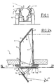
- FIG 1 there is shown schematically a vehicle 1, for example a vehicle of the military type, with which the combatants are brought to move.
- the internal enclosure conventionally constitutes protection against ballistic, nuclear, biological aggressions and chemicals.
- an episcope 3 On the upper wall 2 of the enclosure, we fixes an episcope 3 whose role is to allow a fighter 12 to observe his outside environment, following field E in a direction opposite to the gaze direction. This direction could be good heard that of the look.
- the lower part of an episcope known has been eliminated and replaced with a face retractable reflective.
- the episcope 3 is integrated in an opening 4 made in the wall 2 and comprises conventionally a cover 5 and a transparent mass 6 here equipped with two reflecting faces 6a and 6b.
- the episcope is fixed via the rim 7 of the cover 5, a seal 8 being interposed between this ledge and the wall 2.
- the episcope 3 therefore comprises a entry window 9 arranged substantially vertically at projecting outside and an exit window 10.
- the window 10 is tilted at an acute angle relative to a plane passing through the entrance window 9 to cooperate with a mirror 11 in order to cover the field of vision of the episcope on the one hand and to compensate for the variations of tilt of the mirror related to the size of the observer.
- the light rays coming from outside are therefore think twice before hitting the mirror 11.
- the mirror 11 is made retractable by rotation at using an articulated system comprising a base 13 integral with the rim 7 or the wall 2, for example by screwing or welding.
- the base 13 is provided with a slot 14 longitudinal and an axis 15, held in a position fixed, around which the support 16 of the mirror pivots.
- a connecting rod 17 is fixedly connected to the support 16 by a axis 18 distant from axis 15 and to an axis 19 sliding in the slot 14.
- the articulated system is therefore delimited by the base 13, the support 14 and the connecting rod 17 and gives the mirror 11 any angular position relative to the exit window 10.
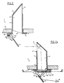
- FIG. 2B there is shown an episcope 6 almost identical to that of FIG. 2A with the exception of the upper part projecting from the enclosure 2.
- the episcope 6 has only one reflective face 6c for transmitting rays bright in the direction of the observer's gaze. The light ray undergoes only one reflection before reaching the mirror 11.
- the slot 14 is made at the base 13. It could be arranged without difficulty on the support 16 of the mirror, the connecting rod 17 being then fixed on the base. There is shown a slot 14 occupying practically the width of the base to allow the retraction of the mirror 11 either towards the base 13 as shown in Figure 3, either opposite to it in the extension of the base as shown in Figure 4.
- FIG. 3 there is shown the mirror 11 in its retracted position, that is, it was brought back against the exit window 10 by rotation, means being provided to maintain this mirror 7 in this position.
- the episcope 3 thus modified no longer constitutes embarrassment for the fighter when he wants to access his post or get out. Congestion, especially in height, is therefore reduced to a minimum.
- the combatant can observe the environment in front (fig. 2B) or behind him (fig.2A).
- the mirror 11 is folded against the base 13 towards the outlet window 10, the connecting rod 17 being applied against the base and the axis 19 being placed at the level of the free end of the slot 14 not visible on the drawing.
- the mirror 11 is folded down in the direction opposite to that of figure 2, the window of outlet 10 being completely clear.
- the axis 19 fixed to the connecting rod 17 is brought back in the vicinity of axis 15 fixed in the vicinity of the other end of the slot 14.
- Figure 5 illustrates another variant of realization of the retraction of the mirror 11 by rotation.
- This mirror is fixed to a support 20 extended by one end 21 semi-cylindrical fixed to the edge 7 of the cover 5 of the episcope 3.
- the end 21 is provided on its periphery a toothing 22 intended to cooperate with a ball 23 subjected to the action of a spring 24 engaged in a housing blind 25 practiced in a bead 26 integrated into the rim 7.
- the support 20 is rotatably mounted by relative to an axis 27 integral with the rim 7 or the wall 2.
- the ball 23 maintains the mirror 11 in the angular position desired by the user.
- the tooth upper determines the retracting position of the mirror and the lower tooth fixes the maximum spacing of the mirror 11 relative to the exit window 10 of the episcope 3.
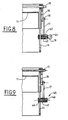
- Figures 6 and 7 illustrate the retraction of the mirror 11 by translation.
- the mirror 11 is integral a support 28 comprising an inclined bottom 29, on which the mirror is fixed, and two side walls 30, one of which only is shown in the figures.
- window 9 could be oriented as shown in Figure 2B.
- the walls 30 carry fingers 31 to slide relative to two guides 32 provided grooves 33 (only one guide is visible in the figures).
- the walls 30 and the guides 32 are arranged two to two on each side of the episcope, for example in the cover 5 thereof.
- Figure 6 shows the position lower of mirror 11 and figure 7 the position retraction to the exit window 10.
- Figures 8 and 9 illustrate sections AA according to the FIG. 2A with a device for indexing the mirror 11.
- Figure 8 shows a first embodiment according to which the connecting rod 17 is rigidly fixed on one side to the support 16 by axis 18 and connected at the other end to the base 13 by the axis 19 extended externally by a button 41.
- the axis 19 slides in a body 42 connected to the base 13, a spring 43 holding said axis in support constant in groove 14 to ensure indexing.
- FIG. 9 illustrates an indexing system 45 according to which constant support is obtained by a ball 46 submitted to the action of a spring 47, the assembly being integrated in a cover 48.
Landscapes
- Physics & Mathematics (AREA)
- Engineering & Computer Science (AREA)
- General Engineering & Computer Science (AREA)
- Optics & Photonics (AREA)
- Astronomy & Astrophysics (AREA)
- General Physics & Mathematics (AREA)
- Rear-View Mirror Devices That Are Mounted On The Exterior Of The Vehicle (AREA)
Claims (10)
- Vorrichtung zur Beobachtung durch die Wand einer Schützumhüllung, wie eines militärischen Fahrzeuges, hindurch mit Hilfe eines Episkopes (3), das im Bereich der Wand (2) befestigt ist, die mit einem äußeren Eintritts-Fenster (9) für Lichtstrahlen und einem inneren Austritts-Fenster (10) versehen ist, umfassend einen Spiegel (11), der mit dem Austritts-Fenster (10) zusammenwirkt, um die Übertragung von Lichtstrahlen in eine Richtung, die jener der Beobachtungsrichtung entgegengesetzt ist, zu gewährleisten, dadurch gekennzeichnet, dass der Spiegel (11) mit Hilfe eines gelenkigen Systems (13, 16, 17) versenkbar ist, das diesen Spiegel (11) mit dem Episkop (3) verbindet, um ihm zu ermöglichen, eine eingefahrene Position, in der er an das Austritts-Fenster (10) angelegt ist und eine ausgefahrene Position einzunehmen, in der er die Beobachtung ermöglicht.
- Vorrichtung zur Beobachtung nach Anspruch 1, dadurch gekennzeichnet, dass der transparente Block (6) eine (9c) oder zwei Reflexionsseiten (9a, 9b) umfasst.
- Vorrichtung zur Beobachtung nach Anspruch 2, dadurch gekennzeichnet, dass der Spiegel (11) durch Drehung versenkbar ist.
- Vorrichtung zur beobachtung nach Anspruch 1, dadurch gekennzeichnet, dass das gelenkige System aus einer Anschlussleiste (13), die mit einem Schlitz (14) versehen ist, einem Träger (16), der an einem Ende der Anschlussleiste angelenkt ist, und einem Arm (17) gebildet, der mit einem Ende mit dem Träger und mit dem anderen mit einem Bolzen (19), der in dem Schlitz gleitet, verbunden ist.
- Vorrichtung zur Beobachtung nach Anspruch 4, dadurch gekennzeichnet, dass das Austrittsfenster (10) des Episkops in einem in Bezug auf eine durch das Eintrittsfenster (9) verlaufende Ebene spitzen Winkel geneigt ist.
- Vorrichtung zur Beobachtung nach Anspruch 5, dadurch gekennzeichnet, dass der Spiegel (11) an das Austrittsfenster oder von diesem weg klappbar ist.
- Vorrichtung zur Beobachtung nach Anspruch 1, dadurch gekennzeichnet, dass das gelenkige System aus einem Träger (20), dessen Ende in bezug auf das Episkop angelenkt ist, gebildet wird und eine halbzylindrische Fläche aufweist, die mit einem Mittel zum Festhalten des Spiegels in einer bestimmten Winkelposition zusammenwirkt.
- Vorrichtung zur Beobachtung nach Anspruch 1, dadurch gekennzeichnet, dass der Spiegel (11) mit Hilfe eines Steuerungssystems (30, 31) durch Verschiebung versenkbar ist, das diesen Spiegel (11) mit dem Episkop (3) verbindet um ihm zu ermöglichen, eine eingefahrene Position, in der er an das Austritts-Fenster (10) angelegt ist und eine gegen den Spiegel ausgefahrene Position einzunehmen, in der er die Beobachtung ermöglicht.
- Vorrichtung zur Beobachtung nach einem der irgendwelchen oben genannten Ansprüchen, dadurch gekennzeichnet, dass sie Mittels entspriecht, um den Spiegel (7) in einer bestimmten Winkelposition zu erhalten.
- Vorrichtung zur Beobachtung nach einem der vorhergehenden Ansprüche, dadurch gekennzeichnet, dass der Spiegel (7) von ebener oder konkaver Bauart ist.
Applications Claiming Priority (2)
| Application Number | Priority Date | Filing Date | Title |
|---|---|---|---|
| FR9712468 | 1997-10-07 | ||
| FR9712468A FR2769378B1 (fr) | 1997-10-07 | 1997-10-07 | Dispositif d'observation a travers la paroi d'une enceinte de protection a l'aide d'un episcope |
Publications (2)
| Publication Number | Publication Date |
|---|---|
| EP0908752A1 EP0908752A1 (de) | 1999-04-14 |
| EP0908752B1 true EP0908752B1 (de) | 2004-07-07 |
Family
ID=9511900
Family Applications (1)
| Application Number | Title | Priority Date | Filing Date |
|---|---|---|---|
| EP19980402361 Expired - Lifetime EP0908752B1 (de) | 1997-10-07 | 1998-09-25 | Vorrichtung zur Beobachtung durch eine Wand eines Schutzgehäuses mit einem Episkop |
Country Status (3)
| Country | Link |
|---|---|
| EP (1) | EP0908752B1 (de) |
| DE (1) | DE69824931T2 (de) |
| FR (1) | FR2769378B1 (de) |
Families Citing this family (5)
| Publication number | Priority date | Publication date | Assignee | Title |
|---|---|---|---|---|
| FR2882445B1 (fr) * | 2005-02-24 | 2007-06-01 | Giat Ind Sa | Dispositif d'observation a episcope escamotable |
| DE102008021486B4 (de) * | 2008-04-29 | 2010-06-24 | Krauss-Maffei Wegmann Gmbh & Co. Kg | Klappwinkelspiegel für Kampffahrzeuge |
| GB2519767B (en) | 2013-10-29 | 2018-05-09 | Kent Periscopes Ltd | Periscope |
| FR3015697A1 (fr) * | 2013-12-19 | 2015-06-26 | France Etat | Episcope de crevel |
| DE102015122411A1 (de) | 2015-12-21 | 2017-06-22 | Krauss-Maffei Wegmann Gmbh & Co. Kg | Klappwinkelspiegel und Ausblickvorrichtung |
Family Cites Families (12)
| Publication number | Priority date | Publication date | Assignee | Title |
|---|---|---|---|---|
| FR407463A (fr) * | 1909-09-30 | 1910-03-01 | Marie Alexandre Leon Lefebure | Appareil reproduisant sous les yeux d'un observateur l'image des objets placés derrière lui |
| US1466567A (en) * | 1920-09-03 | 1923-08-28 | Raymond W Smith | Reflector for autos |
| DE661055C (de) * | 1935-02-04 | 1938-06-09 | Rudolf Gundlach | Periskop fuer gepanzerte Raupenfahrzeuge usw. |
| US2570357A (en) * | 1950-03-08 | 1951-10-09 | Tolly C Martin | Periscope for motor vehicles |
| FR1170518A (fr) * | 1957-04-01 | 1959-01-15 | Dispositif de fixation d'un épiscope de véhicule blindé | |
| US3165573A (en) * | 1958-09-29 | 1965-01-12 | Charles W Moultrie | Vision device for vehicles |
| US3229576A (en) * | 1962-11-21 | 1966-01-18 | Donald W Rees | Hyperbolic ellipsoidal real time display panoramic viewing installation for vehicles |
| US3857632A (en) * | 1971-10-11 | 1974-12-31 | Ichikoh Industries Ltd | Rear vision mirror apparatus having a filter for automobile |
| GB2089519B (en) * | 1980-12-17 | 1984-06-13 | Philips Electronic Associated | Stowable sighting instrument |
| FR2496905A1 (fr) * | 1980-12-24 | 1982-06-25 | France Etat | Episcope a reflexions multimodes |
| DE4015346A1 (de) * | 1990-05-12 | 1991-11-14 | Wegmann & Co | Kampffahrzeug, insbesondere kampfpanzer, mit einer im gepanzerten gehaeusedach des fahrzeugs angeordneten luke |
| DE4200261A1 (de) * | 1992-01-08 | 1993-07-15 | Wegmann & Co Gmbh | Winkelspiegel an der ein- ausstiegsluke eines kampffahrzeuges |
-
1997
- 1997-10-07 FR FR9712468A patent/FR2769378B1/fr not_active Expired - Fee Related
-
1998
- 1998-09-25 DE DE69824931T patent/DE69824931T2/de not_active Expired - Lifetime
- 1998-09-25 EP EP19980402361 patent/EP0908752B1/de not_active Expired - Lifetime
Also Published As
| Publication number | Publication date |
|---|---|
| EP0908752A1 (de) | 1999-04-14 |
| FR2769378B1 (fr) | 2000-12-29 |
| FR2769378A1 (fr) | 1999-04-09 |
| DE69824931T2 (de) | 2005-07-21 |
| DE69824931D1 (de) | 2004-08-12 |
Similar Documents
| Publication | Publication Date | Title |
|---|---|---|
| EP1948465B1 (de) | Einziehbare anzeigevorrichtung für ein kraftfahrzeug und damit ausgerüstetes kraftfahrzeug | |
| EP3404176B1 (de) | Vorrichtung zum entriegeln eines türschlosses | |
| EP1648737B1 (de) | Rückblickvorrichtung für ein kraftfahrzeug | |
| EP1108580B1 (de) | Heckklappe für ein Motorfahrzeug | |
| EP0136951B1 (de) | Mehrzweckvorrichtung für die Projektion sowie Retroprojektion von Diapositiven | |
| EP0908752B1 (de) | Vorrichtung zur Beobachtung durch eine Wand eines Schutzgehäuses mit einem Episkop | |
| EP0192549B1 (de) | Antischwingende Vorrichtung für einen Fahrzeugrückblickspiegel | |
| EP2401442A1 (de) | Leuchtkasten mit öffnung durch einen federbelasteten feststeller | |
| WO2019048777A1 (fr) | Systeme de recouvrement d'un compartiment a bagages de vehicule automobile | |
| EP0192309A1 (de) | Tag-Nacht-Sichtgerät | |
| EP3016821B1 (de) | Kofferraumabdeckungssystem für kraftfahrzeug | |
| FR3107679A1 (fr) | Système de liaison destiné au montage d’un bac de rangement sur un support fixé à une caisse d'un véhicule automobile. | |
| EP0193236A1 (de) | Tag-Nachtsichtgerät mit weitem Sehfeld | |
| EP0770517A1 (de) | Zusatzsitz | |
| EP3755966B1 (de) | Schutzvorrichtung für einen ausrichtbaren sucher | |
| FR2793754A1 (fr) | Hayon arriere pour vehicule automobile | |
| EP3524476B1 (de) | Abschirmungsvorrichtung für fahrzeug | |
| EP3553585B1 (de) | Head-up anzeigesystem | |
| FR3078666A1 (fr) | Dispositif de compartimentage pour coffre de vehicule automobile. | |
| FR3064660A1 (fr) | Dispositif de verrouillage pour couvercle de compartiment de rangement, compartiment de rangement associe et vehicule associe | |
| FR2865567A1 (fr) | Dispositif d'affichage pour vehicule automobile. | |
| EP0741982A1 (de) | Schminkvorrichtung für die Augen und Schaustand damit ausgestattet | |
| EP3670271B1 (de) | Bewegungsvorrichtung einer kamera für ein motorgetriebenes fahrzeug | |
| FR2760611A1 (fr) | Dispositif de rangement forme dans une manchette de canape ou fauteuil | |
| FR2888274A1 (fr) | Mecanisme de support d'un ouvrant de vehicule automobile et vehicule automobile en comportant application |
Legal Events
| Date | Code | Title | Description |
|---|---|---|---|
| PUAI | Public reference made under article 153(3) epc to a published international application that has entered the european phase |
Free format text: ORIGINAL CODE: 0009012 |
|
| AK | Designated contracting states |
Kind code of ref document: A1 Designated state(s): DE FR GB |
|
| AX | Request for extension of the european patent |
Free format text: AL;LT;LV;MK;RO;SI |
|
| 17P | Request for examination filed |
Effective date: 19990510 |
|
| AKX | Designation fees paid |
Free format text: DE FR GB |
|
| 17Q | First examination report despatched |
Effective date: 20030113 |
|
| GRAP | Despatch of communication of intention to grant a patent |
Free format text: ORIGINAL CODE: EPIDOSNIGR1 |
|
| GRAS | Grant fee paid |
Free format text: ORIGINAL CODE: EPIDOSNIGR3 |
|
| GRAA | (expected) grant |
Free format text: ORIGINAL CODE: 0009210 |
|
| AK | Designated contracting states |
Kind code of ref document: B1 Designated state(s): DE FR GB |
|
| REG | Reference to a national code |
Ref country code: GB Ref legal event code: FG4D Free format text: NOT ENGLISH |
|
| GBT | Gb: translation of ep patent filed (gb section 77(6)(a)/1977) |
Effective date: 20040707 |
|
| REF | Corresponds to: |
Ref document number: 69824931 Country of ref document: DE Date of ref document: 20040812 Kind code of ref document: P |
|
| PLBE | No opposition filed within time limit |
Free format text: ORIGINAL CODE: 0009261 |
|
| STAA | Information on the status of an ep patent application or granted ep patent |
Free format text: STATUS: NO OPPOSITION FILED WITHIN TIME LIMIT |
|
| 26N | No opposition filed |
Effective date: 20050408 |
|
| REG | Reference to a national code |
Ref country code: FR Ref legal event code: TP |
|
| REG | Reference to a national code |
Ref country code: DE Ref legal event code: R082 Ref document number: 69824931 Country of ref document: DE Representative=s name: HUBER & SCHUESSLER, DE |
|
| REG | Reference to a national code |
Ref country code: GB Ref legal event code: 732E Free format text: REGISTERED BETWEEN 20150220 AND 20150225 |
|
| REG | Reference to a national code |
Ref country code: DE Ref legal event code: R082 Ref document number: 69824931 Country of ref document: DE Representative=s name: HUBER & SCHUESSLER, DE Effective date: 20150215 Ref country code: DE Ref legal event code: R081 Ref document number: 69824931 Country of ref document: DE Owner name: OPTSYS, FR Free format text: FORMER OWNER: GIAT INDUSTRIES, VERSAILLES, FR Effective date: 20150215 |
|
| REG | Reference to a national code |
Ref country code: FR Ref legal event code: PLFP Year of fee payment: 19 |
|
| REG | Reference to a national code |
Ref country code: FR Ref legal event code: PLFP Year of fee payment: 20 |
|
| PGFP | Annual fee paid to national office [announced via postgrant information from national office to epo] |
Ref country code: DE Payment date: 20170821 Year of fee payment: 20 Ref country code: FR Payment date: 20170822 Year of fee payment: 20 Ref country code: GB Payment date: 20170821 Year of fee payment: 20 |
|
| REG | Reference to a national code |
Ref country code: DE Ref legal event code: R071 Ref document number: 69824931 Country of ref document: DE |
|
| REG | Reference to a national code |
Ref country code: GB Ref legal event code: PE20 Expiry date: 20180924 |
|
| PG25 | Lapsed in a contracting state [announced via postgrant information from national office to epo] |
Ref country code: GB Free format text: LAPSE BECAUSE OF EXPIRATION OF PROTECTION Effective date: 20180924 |