EP0908738B1 - NMR-Probenkopf mit integrierter Fernabstimmung - Google Patents
NMR-Probenkopf mit integrierter Fernabstimmung Download PDFInfo
- Publication number
- EP0908738B1 EP0908738B1 EP98118920A EP98118920A EP0908738B1 EP 0908738 B1 EP0908738 B1 EP 0908738B1 EP 98118920 A EP98118920 A EP 98118920A EP 98118920 A EP98118920 A EP 98118920A EP 0908738 B1 EP0908738 B1 EP 0908738B1
- Authority
- EP
- European Patent Office
- Prior art keywords
- nmr
- motors
- magnet
- actuator
- miniaturized
- Prior art date
- Legal status (The legal status is an assumption and is not a legal conclusion. Google has not performed a legal analysis and makes no representation as to the accuracy of the status listed.)
- Expired - Lifetime
Links
Images



Classifications
-
- G—PHYSICS
- G01—MEASURING; TESTING
- G01R—MEASURING ELECTRIC VARIABLES; MEASURING MAGNETIC VARIABLES
- G01R33/00—Arrangements or instruments for measuring magnetic variables
- G01R33/20—Arrangements or instruments for measuring magnetic variables involving magnetic resonance
- G01R33/28—Details of apparatus provided for in groups G01R33/44 - G01R33/64
-
- G—PHYSICS
- G01—MEASURING; TESTING
- G01R—MEASURING ELECTRIC VARIABLES; MEASURING MAGNETIC VARIABLES
- G01R33/00—Arrangements or instruments for measuring magnetic variables
- G01R33/20—Arrangements or instruments for measuring magnetic variables involving magnetic resonance
- G01R33/28—Details of apparatus provided for in groups G01R33/44 - G01R33/64
- G01R33/32—Excitation or detection systems, e.g. using radio frequency signals
- G01R33/36—Electrical details, e.g. matching or coupling of the coil to the receiver
- G01R33/3628—Tuning/matching of the transmit/receive coil
Definitions
- the invention relates to a nuclear magnetic resonance (NMR) Spectrometer with an NMR magnet, a probe head and an actuator for the remote adjustment of electrical and / or mechanical units, for example capacitive trimmers, variable resistors, adjustable inductors etc., in the probe head with a or more drive units, one or more Gear units and one or more drive shafts, which are coupled to the adjustment rods of the sample head.
- NMR nuclear magnetic resonance
- NMR spectrometer with such an actuator is known for example from EP 0 518 100 B1.
- NMR nuclear magnetic resonance
- the known actuators 34 for probe heads in NMR spectrometers each contain at least one drive unit, which normally consists of an electric motor.
- the actuator is not positioned too close to the magnets, since the engine adversely affected by its ferromagnetic and permanent-magnetic components, the homogeneity of the H o; field of the magnet.
- high electromagnetic forces can arise between the magnet coil and the motor, which could put a critical load on both the magnet / dewar system and the motor. And last but not least, these electric motors lose their functionality in high stray fields.
- the electric motors which are located in the actuator 34, are placed at a sufficiently large distance from the magnetic center 32 of the magnet and via a long connecting rod 33, which consists either of individual cardan shafts or of individual flexible mechanical shafts, with the adjustment rods 8a , 8b, 8c of the probe head connected.
- the object of the present invention is to an actuator for an NMR spectrometer at the beginning described in such a way that it improves the user more freedom of movement and therefore comfort below the Magnets offers by taking up the space required by the actuator minimized and access to the area below the magnet is optimized.
- Another object of the invention is in making the installation of the actuator more convenient shape. In the known actuators, the User after each change of the probe Linkage of the actuator to the Connect the sample head. In the actuator according to the invention that should no longer be necessary.
- the actuator is attached to the NMR probe head, that the drive unit (s) comprise one or more miniaturized DC motors with permanent magnets serving as a stator and with a volume V ⁇ 10 cm 3 for generating torques, and that The miniaturized DC motor (s) are arranged in the stray field of the NMR magnet.
- DE 34 21 830 A1 is an actuator for remote adjustment of a capacitive trimmer High-frequency antenna in an NMR tomograph with a Drive unit, a gear unit and one Drive shaft known, that with the high-frequency antenna is structurally united and thus as "integral Component "of the radio frequency antenna are considered can, but is expressly in DE 34 21 830 A1 pointed out that stepper motors in NMR apparatus basically arranged outside the main field magnet have to be in order not to disturb the field homogeneity and so as not to function through the stray field itself to be affected. This runs according to the invention Placement of the DC motors in the stray field of the Main field magnets diametrically opposed.
- the key to realizing the inventive idea lies on the one hand in a consistent miniaturization of the Actuator and on the other hand in an optimization of Functionality of the drive unit in high Stray fields.
- a highly miniaturized electric motor ie a miniature motor, can therefore be attached directly to the lower part of the sample head without the H o field at the location of the measurement sample being influenced too much.
- miniaturization is also one of the prerequisites so that the actuator can be integrated into the probe head at all.
- An embodiment of the is particularly advantageous Invention in which the miniaturized DC motors have integrated miniature gearboxes, which makes the Drive and gear units are particularly compact can be.
- DC motors Dimensions in the order of 7mm x 20mm (without Gear) and 7mm x 30mm (with gear) and deliver Torque of approximately 0.035 Nm (with gear).
- One inside horizontal stator consists of a cylindrical one Permanent magnet (e.g. Alnico), whose field inference via an external steel cylinder. In between is a rotor that contains no iron Copper windings exist and has a commutator.
- the stray field of the NMR magnet has namely an influence on the magnetic states within the Motors and can in this way its functionality deteriorate.
- the orientation of the permanent magnet in the Motor in relation to the stray field of the NMR magnet should therefore be chosen so that the engine is as optimal as possible works.
- the field strength of the Stray field small compared to the coercive force of the Is permanent magnet, it means that that Stray field has practically no influence on the Owns permanent magnets. In this case, it should Stray field and the field in the air gap of the permanent magnet have the same direction as possible so that the field in Air gap and thus the torque is increased.
- the orientation of the motor should be chosen so that the stray field of the NMR magnet the field inside the Permanent magnets supported, i.e. essentially the has the same direction. This prevents one Weakening of the permanent magnet, but leads on the other hand a weakening of the field in the air gap of the engine and thus a reduction in torque.
- the permanent magnet is weakened would have resulted in an even greater reduction of the torque.
- An embodiment of the is also advantageous Actuator modified according to the invention, in which the Gear units bevel gear and a 90 ° to Shaft of the respective drive unit turned drive shaft exhibit.
- This allows the drive units to move laterally from the vertical axis of the NMR structure so that the low space below that usually used NMR cryostats can be better used.
- the Assembly of the actuator is thus simplified.
- bevel gears desired with the bevel gearboxes Speed ratio ratios between the drive motor and the adjustment rod operated with it become.
- the Drive shaft on a slip clutch This allows the Build up excessive torques and one of them resulting damage in the sample head area avoided become.
- a particularly simple and therefore quick installation on the Probe head allows an embodiment of the Actuator modified according to the invention, in which the Drive shafts automatically into the adjustment rods can snap into place.
- FIG. 1a shows an NMR probe head consisting of a lower part 6 and an upper part 7.
- HF cables 9a seen with which the connections from the NMR receiving coils with their matching networks to the RF output sockets 9b can be produced.
- the NMR signal is again via RF cable 35 (see FIG. 4) led to preamplifiers 36 (see Fig. 4), which in general somewhat outside the stray field of the NMR magnet to be assembled.
- the adjustment rods are also in the lower part 6 8a, 8b, 8c to see the capacities for the resonance and power adjustment can be set. It three such adjustment rods are shown, it can but also be less or more available.
- Fig.1b shows an embodiment of the invention Actuator 1, which has several small motors inside installed (see Fig. 3).
- On the top side are drive shafts 2a, 2b, 2c can be seen, each of a separate Small motor is driven and one at the outer end has screwdriver-shaped approach. These ends fit into the slotted ends of the adjustment rods 8a, 8b, 8c, so that a transmission of the torques of the drive shafts on the adjustment rods 8a, 8b, 8c becomes.
- the electrical energy required by the smallest motors is via a plug 5 and an electrical lead 4th delivered.
- the actuator 1 is with the help of bolts 3a, 3b (only two are shown, the others are hidden and not seen) screwed to the lower part 6 of the sample head.
- Fig.1c shows the actuator 1, which on the lower part 6 of the Porbenkopf is screwed.
- the drive shafts 2a, 2b, 2c and the adjustment rods 8a, 8b, 8c are locked in place Condition shown.
- Fig.1d is an electronic unit belonging to the actuator 1 10 shown. This receives the via a socket 11 required control commands from a computer and puts them in corresponding current values, which they send to the individual Micro motors forwards.
- the electrical connection between the smallest motors in actuator 1 and the electronics unit 10 runs over the cable 4 and the plug 5.
- a transmission part 13 provided that shown in Fig.2b in side view is. This allows with the help of a bolt 14 and a slot 15 a transmission of the torque, and with Help of a spring 17 and thanks to the slot 15 a sufficient great play along the axis of the drive shaft 2a. Both together means that firstly the torque is transmitted, and second, an automatic snap between the Slot of the rotating drive shaft 2a and the screwdriver-shaped Approach of the adjustment rod 8a is reached.
- a guide sleeve 12 attached to the adjustment rod 8a is used to position the drive shaft 2a and the adjustment rod 8a to facilitate.
- a guide plate 25 is provided with individual slide bearings 26, with which the lower section 24 of the drive shaft 18 who fastens the transmission part 13 by means of a bolt 16 as well as all other drive axles.
- the lower area of the actuator is covered 27 completed.
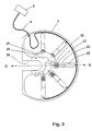
- FIG. 3 shows the view of the actuator 1 seen from below and without the cover 27.
- the cutting plane defines A-A the sectional drawing of Fig.2a. Part of the guide plate 25 with its slide bearings 26 is also closed see.
- the actuator contains five small motors, it can however, there may also be fewer or more. In detail you can see the two bevel gears 20 and 21, the miniaturized multi-stage integrated planetary gear 23 and the motor 22. The electrical connections to the individual motors are summarized in cable 4, and this is connected to the connector 5.
- a slot 28 provides the space necessary for the transfer dewar, the lower part 6 of the probe head with the lower one Area of the receiving coil connects to assemble.
- This Transfer-Dewar is part of a temperature control unit 38 (see Fig. 4), with which the NMR measurement sample at different temperatures can be brought.
- Fig. 4 shows the current state of the art.
- a cryostat 29 there is a superconducting NRM magnet 31.
- the cryostat 29 has a continuous, vertical bore 30, usually about 5 cm in diameter, which is at room temperature.
- a probe head made from the Lower part 6 and the upper part 7 is located in the Bore 30 so that the center of the NMR receiving coil coincides with the center of the magnet 31 and is defined by a point 32.
- On the lower part 6 of the sample head are the adjustment rods 8a, 8b, 8c, which via a linkage 33 with a conventional Actuator 34 are connected.
- the linkage 33 has the task of the torques generated in the actuator 34 to be transferred to the adjustment rods 8a, 8b, 8c.
- the high frequency NMR signal is from the lower part 6 of the probe via the RF connection cable 35 to the preamplifiers 36 led.
- On the lower part 6 of the sample head is also a thermally insulated and flexible connecting pipe 37 connected, which is connected to the temperature control unit 38 and is used to produce a cooled or heated gas (usually Nitrogen) from the temperature control unit 38 to the sample head where it is then mounted in the probe head Glasdewar reached the measurement sample.
- a cooled or heated gas usually Nitrogen
- Fig. 4 clearly illustrates how the area below the NMR magnets 31 through various arrangements, especially that Linkage 33, is blocked and free access to the probe head.
Landscapes
- Physics & Mathematics (AREA)
- Condensed Matter Physics & Semiconductors (AREA)
- General Physics & Mathematics (AREA)
- Magnetic Resonance Imaging Apparatus (AREA)
- Reciprocating, Oscillating Or Vibrating Motors (AREA)
- Connection Of Motors, Electrical Generators, Mechanical Devices, And The Like (AREA)
Description
- Fig.1a
- eine schematisierte Seitenansicht eines NMR-Probenkopfes;
- Fig.1b
- einen zum NMR-Probenkopf nach Fig. 1a passenden erfindungsgemässen Stellantrieb;
- Fig. 1c
- den NMR-Probenkopf nach Fig. 1a mit eingebautem Stellantrieb nach Fig. 1b;
- Fig.1d
- den Aufbau nach Fig. 1c ergänzt um eine elektronische Steuereinheit;
- Fig.2a
- einen vergrösserten, schematischen vertikalen Teilschnitt durch den Aufbau nach Fig. 1c;
- Fig.2b
- eine Seitenansicht auf das in Fig. 2a gezeigte Übertragungsteil;
- Fig.3
- eine horizontale Schnittansicht von oben auf die Antriebs- und Getriebeeinheiten nach Fig. 2a; und
- Fig.4
- eine schematisierte, teilweise transparente Seitenansicht auf ein NMR-Spektrometer nach dem Stand der Technik.
Claims (7)
- NMR-Spektrometer mit einem Kernspinresonanz(NMR)-Magneten (31), einem Probenkopf (6, 7) und einem Stellantrieb zur fernbedienten Verstellung von elektrischen und/oder mechanischen Einheiten, beispielsweise kapazitiven Trimmern, Regelwiderständen, verstellbaren Induktivitäten etc., im Probenkopf (6,7) mit einer oder mehreren Antriebseinheiten, einer oder mehreren Getriebeeinheiten sowie einer oder mehreren Antriebswellen, die mit Justierungsstangen (8a, 8b, 8c) des Probenkopfes gekoppelt sind,
dadurch gekennzeichnet, dass der Stellantrieb (1) am NMR-Probenkopf (6,7) befestigt ist, dass die Antriebseinheit(en) einen oder mehrere miniaturisierte Gleichstrommotoren (22) mit als Stator dienenden Permanentmagneten und mit einem Volumen V≤10cm3 zur Erzeugung von Drehmomenten umfassen, und dass der (die) miniaturisierte(n) Gleichstrommotor(en) (22) im Streufeld des NMR-Magneten (31) angeordnet ist (sind). - NMR-Spektrometer nach Anspruch 1, dadurch gekennzeichnet, dass die miniaturisierten Gleichstrommotoren (22) integrierte Miniatur-Getriebe (23) aufweisen.
- NMR-Spektrometer nach Anspruch 1 oder 2, dadurch gekennzeichnet, dass die miniaturisierten Gleichstrommotoren (22) in einem Streufeld arbeiten können, das kleiner als die Koerzitivkraft von als Stator der Gleichstrommotoren (22) dienenden Permanentmagneten ist, wobei das Magnetfeld im Luftspalt jedes Motors weitgehend in gleicher Richtung wie das Streufeld des NMR-Magneten am Ort des Luftspalts orientiert ist.
- NMR-Spektrometer nach Anspruch 1 oder 2, dadurch gekennzeichnet, dass die miniaturisierten Gleichstrommotoren (22) in einem Streufeld arbeiten können, das mit der Koerzitivkraft von als Stator der Gleichstrommotoren (22) dienenden Permanentmagneten vergleichbar ist, wobei das Feld innerhalb der Permanentmagneten weitgehend in gleicher Richtung wie das Streufeld des NMR-Magneten am Ort der Permanentmagneten orientiert ist.
- NMR-Spektrometer nach einem der vorhergehenden Ansprüche, dadurch gekennzeichnet, dass die Getriebeeinheiten Kegelrad-Getriebe (20, 21) sowie eine um 90° zur Welle der jeweiligen Antriebseinheit gedrehte Antriebswelle (18) aufweisen.
- NMR-Spektrometer nach einem der vorhergehenden Ansprüche, dadurch gekennzeichnet, dass an der Antriebswelle (18) eine Rutschkupplung (19a, 19b) vorgesehen ist.
- NMR-Spektrometer nach einem der vorhergehenden Ansprüche, dadurch gekennzeichnet, dass die Antriebswellen selbständig in die Justierungsstangen (8a, 8b, 8c) einrasten können.
Applications Claiming Priority (2)
| Application Number | Priority Date | Filing Date | Title |
|---|---|---|---|
| DE19744763A DE19744763C2 (de) | 1997-10-10 | 1997-10-10 | NMR-Probenkopf mit integrierter Fernabstimmung |
| DE19744763 | 1997-10-10 |
Publications (3)
| Publication Number | Publication Date |
|---|---|
| EP0908738A2 EP0908738A2 (de) | 1999-04-14 |
| EP0908738A3 EP0908738A3 (de) | 2000-03-22 |
| EP0908738B1 true EP0908738B1 (de) | 2002-01-23 |
Family
ID=7845144
Family Applications (1)
| Application Number | Title | Priority Date | Filing Date |
|---|---|---|---|
| EP98118920A Expired - Lifetime EP0908738B1 (de) | 1997-10-10 | 1998-10-07 | NMR-Probenkopf mit integrierter Fernabstimmung |
Country Status (4)
| Country | Link |
|---|---|
| US (1) | US6204665B1 (de) |
| EP (1) | EP0908738B1 (de) |
| JP (1) | JP3164555B2 (de) |
| DE (2) | DE19744763C2 (de) |
Cited By (1)
| Publication number | Priority date | Publication date | Assignee | Title |
|---|---|---|---|---|
| EP4647795A1 (de) | 2024-05-07 | 2025-11-12 | Bruker Biospin GmbH & Co. KG | Nmr-probenkopf mit kompaktem mechanismus zur fernabstimmung, -anpassung und -steuerung einer nmr-probe |
Families Citing this family (25)
| Publication number | Priority date | Publication date | Assignee | Title |
|---|---|---|---|---|
| US6323647B1 (en) | 1999-09-16 | 2001-11-27 | Varian, Inc. | Motor driven tuning and matching of RF coils in an NMR probe |
| DE10019990C2 (de) * | 2000-04-22 | 2002-04-04 | Bruker Analytik Gmbh | Probenkopf für Kernresonanzmessungen |
| US6720769B2 (en) * | 2001-07-27 | 2004-04-13 | The University Of Chicago | Rotational exchange gradient imager for in situ magnetic resonance analyses in ultracentrifuge sedimentation of biological materials and rheology investigations |
| JP2003130937A (ja) * | 2001-10-24 | 2003-05-08 | Hitachi Ltd | 溶液用核磁気共鳴分析装置 |
| US6774634B2 (en) | 2002-01-29 | 2004-08-10 | Varian, Inc. | Automated NMR analysis using solvents and sample tube materials to control frequency shifts |
| EE00330U1 (et) * | 2002-05-30 | 2002-10-15 | Keemilise ja Bioloogilise F��sika Instituut | Tuuma magnetresonants-spektromeetri mõõtepea |
| DE10225958B3 (de) * | 2002-06-12 | 2004-03-04 | Bruker Biospin Ag | Vorrichtung zur Positionierung eines mit einer Messsubstanz gefüllten länglichen Probenröhrchens relativ zu einem NMR-Empfangsspulensystem |
| WO2005057232A1 (en) * | 2003-12-08 | 2005-06-23 | Philips Intellectual Property & Standards Gmbh | Circuit arrangement for detuning a resonant circuit of an mr apparatus |
| US7701219B2 (en) * | 2004-03-31 | 2010-04-20 | Varian, Inc. | Capacitor switches for NMR |
| AU2005230449B2 (en) * | 2004-04-01 | 2010-02-18 | Liposcience, Inc. | NMR clinical analyzers and related methods, systems, modules and computer program products for clinical evaluation of biosamples |
| US7319326B2 (en) * | 2004-09-23 | 2008-01-15 | University Of New Brunswick | Sensor and magnetic field apparatus suitable for use in for unilateral nuclear magnetic resonance and method for making same |
| DE102005013620B3 (de) * | 2005-03-24 | 2006-07-27 | Bruker Biospin Ag | Kryostatanordnung mit thermisch kompensierter Zentrierung |
| DE102005041383B4 (de) * | 2005-09-01 | 2007-09-27 | Bruker Biospin Ag | NMR-Apparatur mit gemeinsam gekühltem Probenkopf und Kryobehälter und Verfahren zum Betrieb derselben |
| US8237440B2 (en) * | 2005-09-23 | 2012-08-07 | University Of New Brunswick | Magnetic field generator suitable for unilateral nuclear magnetic resonance and method for making same |
| CA2672699A1 (en) * | 2006-11-24 | 2008-05-29 | University Of New Brunswick | Magnet array |
| US7701228B2 (en) * | 2008-03-11 | 2010-04-20 | Varian, Inc. | Switchable manual/motor-driven NMR tuning systems and methods |
| US7800369B2 (en) * | 2008-05-30 | 2010-09-21 | Varian, Inc. | Hybrid automatic tuning/matching for NMR probes |
| US20110066026A1 (en) * | 2009-04-21 | 2011-03-17 | The Regents Of The University Of California | Rf coil for use in magnetic resonance imaging in integrated spect and mr imaging |
| EP2616830A2 (de) * | 2010-09-16 | 2013-07-24 | Ago Samoson | Nmr-sondenköpfe und verfahren mit multifunktionaler probenrotation |
| FR2981442A1 (fr) * | 2011-10-17 | 2013-04-19 | Bruker Biospin | Dispositif d'alimentation en gaz froids et installation rmn comprenant un tel dispositif |
| DE102013204131B3 (de) | 2013-03-11 | 2014-02-06 | Bruker Biospin Ag | NMR-Probenkopf mit einem mittels eines piezoelektrischen Aktors diskret verstellbaren variablen Kondensator im HF-Schwingkreis |
| CN106483481B (zh) * | 2016-12-20 | 2020-09-15 | 河南中医药大学 | 一种核磁共振磁体组件 |
| CN111566496B (zh) * | 2017-11-23 | 2023-06-02 | 通泰克股份公司 | 带压电致动器的nmr探头 |
| DE102021214453A1 (de) | 2021-12-15 | 2023-06-15 | Bruker Biospin Gmbh | Befestigung eines NMR-Probenkopfs am Shimrohr-Ende desNMR-Magneten mit automatisierbaren Funktionsverbindungen als passgenaue Stecker/Steckerbuchsen-Paar und NMR-Spektrometer |
| CA3265215A1 (en) * | 2022-08-19 | 2024-02-22 | Quantum Valley Investment Fund LP | SAMPLE CHANGE IN A MAGNETIC RESONANCE SYSTEM |
Family Cites Families (8)
| Publication number | Priority date | Publication date | Assignee | Title |
|---|---|---|---|---|
| DE8328726U1 (de) * | 1983-10-05 | 1986-02-20 | Siemens AG, 1000 Berlin und 8000 München | Gerät zur Erzeugung von Bildern eines Untersuchungsobjektes |
| DE3421830A1 (de) * | 1984-06-13 | 1985-12-19 | Philips Patentverwaltung Gmbh, 2000 Hamburg | Kernspinresonanzgeraet mit einem stellglied zur anpassung oder zum nachstimmen des resonators |
| JPS63200742A (ja) | 1987-02-16 | 1988-08-19 | 三菱電機株式会社 | コアレスモ−タ |
| JPH0616076B2 (ja) | 1987-07-27 | 1994-03-02 | 株式会社東芝 | 磁気共鳴イメージング装置 |
| JPH03258242A (ja) * | 1990-03-09 | 1991-11-18 | Toshiba Corp | 磁気共鳴イメージング装置 |
| US5247330A (en) * | 1990-08-02 | 1993-09-21 | Canon Kabushiki Kaisha | Image input device |
| DE4119674A1 (de) * | 1991-06-14 | 1992-12-17 | Spectrospin Ag | Stellantrieb |
| JPH05276239A (ja) | 1992-03-24 | 1993-10-22 | Sharp Corp | 多機能電話機 |
-
1997
- 1997-10-10 DE DE19744763A patent/DE19744763C2/de not_active Expired - Fee Related
-
1998
- 1998-09-28 US US09/161,298 patent/US6204665B1/en not_active Expired - Lifetime
- 1998-10-07 EP EP98118920A patent/EP0908738B1/de not_active Expired - Lifetime
- 1998-10-07 DE DE59802885T patent/DE59802885D1/de not_active Expired - Lifetime
- 1998-10-09 JP JP30175998A patent/JP3164555B2/ja not_active Expired - Fee Related
Cited By (1)
| Publication number | Priority date | Publication date | Assignee | Title |
|---|---|---|---|---|
| EP4647795A1 (de) | 2024-05-07 | 2025-11-12 | Bruker Biospin GmbH & Co. KG | Nmr-probenkopf mit kompaktem mechanismus zur fernabstimmung, -anpassung und -steuerung einer nmr-probe |
Also Published As
| Publication number | Publication date |
|---|---|
| US6204665B1 (en) | 2001-03-20 |
| EP0908738A2 (de) | 1999-04-14 |
| JP3164555B2 (ja) | 2001-05-08 |
| DE59802885D1 (de) | 2002-03-14 |
| EP0908738A3 (de) | 2000-03-22 |
| JPH11223668A (ja) | 1999-08-17 |
| DE19744763A1 (de) | 1999-05-27 |
| DE19744763C2 (de) | 1999-09-02 |
Similar Documents
| Publication | Publication Date | Title |
|---|---|---|
| EP0908738B1 (de) | NMR-Probenkopf mit integrierter Fernabstimmung | |
| DE69901599T2 (de) | Linearbeschleuniger | |
| DE10213565B3 (de) | Hochfrequenzantenne für eine Magnetresonanzanlage | |
| DE19947539B4 (de) | Gradientenspulenanordnung mit Dämpfung innerer mechanischer Schwingungen | |
| DE3888456T2 (de) | Dielektrischer Resonator. | |
| DE4223909C2 (de) | Vorrichtungen zum Messen magnetischer Resonanz | |
| DE10226511A1 (de) | MR-Anordnung mit Hochfrequenzspulenarrays | |
| WO1990013824A1 (de) | Magnetsystem mit supraleitenden feldspulen | |
| EP0122596B1 (de) | Wälzringspindeltrieb | |
| DE4018657A1 (de) | Probenkopf fuer kernresonanz-spektrometer | |
| EP0896744A1 (de) | Dual-mode-mikrowellen-bandpassfilter aus hochgüteresonatoren | |
| EP0518100B1 (de) | Stellantrieb | |
| DE19523220A1 (de) | Mikrowellenfilter | |
| DE102016224979A1 (de) | Elektrisch steuerbare Justagevorrichtung | |
| DE69110494T2 (de) | Abstimmbarer Mikrowellenfilter. | |
| DE1938722A1 (de) | Hochfrequenzkopf-System fuer eine Apparatur zur Messung der kernmagnetischen Resonanz | |
| DE10227877B4 (de) | Aktiv abgeschirmte, supraleitende Magnetanordnung mit einer Vorrichtung zur zusätzlichen Streufeldoptimierung | |
| EP3093681B1 (de) | Eine modular aufgebaute anordnung von gradienten- oder shimspulen | |
| DE4312410C2 (de) | Abstimmbare ferrimagnetische Resonatorschaltung | |
| DE10010967A1 (de) | Hohlraumresonator mit abstimmbarer Resonanzfrequenz | |
| DE102005013293A1 (de) | Magnetresonanzanlage | |
| DE10016229B4 (de) | Polarisierende Antenne für ein Magnetresonanzgerät | |
| DE4333182A1 (de) | Doppeltresonante Antennenanordnung für ein Magnetresonanzgerät | |
| WO2018019876A1 (de) | Spulenanordnung | |
| DE69713803T2 (de) | Feststehende abstimmbare schleife |
Legal Events
| Date | Code | Title | Description |
|---|---|---|---|
| PUAI | Public reference made under article 153(3) epc to a published international application that has entered the european phase |
Free format text: ORIGINAL CODE: 0009012 |
|
| AK | Designated contracting states |
Kind code of ref document: A2 Designated state(s): CH DE FR GB LI |
|
| AX | Request for extension of the european patent |
Free format text: AL;LT;LV;MK;RO;SI |
|
| PUAL | Search report despatched |
Free format text: ORIGINAL CODE: 0009013 |
|
| AK | Designated contracting states |
Kind code of ref document: A3 Designated state(s): AT BE CH CY DE DK ES FI FR GB GR IE IT LI LU MC NL PT SE |
|
| AX | Request for extension of the european patent |
Free format text: AL;LT;LV;MK;RO;SI |
|
| 17P | Request for examination filed |
Effective date: 20000307 |
|
| 17Q | First examination report despatched |
Effective date: 20000607 |
|
| AKX | Designation fees paid |
Free format text: CH DE FR GB LI |
|
| GRAG | Despatch of communication of intention to grant |
Free format text: ORIGINAL CODE: EPIDOS AGRA |
|
| GRAG | Despatch of communication of intention to grant |
Free format text: ORIGINAL CODE: EPIDOS AGRA |
|
| GRAH | Despatch of communication of intention to grant a patent |
Free format text: ORIGINAL CODE: EPIDOS IGRA |
|
| GRAH | Despatch of communication of intention to grant a patent |
Free format text: ORIGINAL CODE: EPIDOS IGRA |
|
| GRAA | (expected) grant |
Free format text: ORIGINAL CODE: 0009210 |
|
| REG | Reference to a national code |
Ref country code: GB Ref legal event code: IF02 |
|
| AK | Designated contracting states |
Kind code of ref document: B1 Designated state(s): CH DE FR GB LI |
|
| REG | Reference to a national code |
Ref country code: CH Ref legal event code: EP |
|
| REG | Reference to a national code |
Ref country code: CH Ref legal event code: NV Representative=s name: TROESCH SCHEIDEGGER WERNER AG |
|
| REF | Corresponds to: |
Ref document number: 59802885 Country of ref document: DE Date of ref document: 20020314 |
|
| ET | Fr: translation filed | ||
| GBT | Gb: translation of ep patent filed (gb section 77(6)(a)/1977) |
Effective date: 20020415 |
|
| REG | Reference to a national code |
Ref country code: CH Ref legal event code: PFA Free format text: BRUKER AG TRANSFER- BRUKER BIOSPIN AG |
|
| REG | Reference to a national code |
Ref country code: FR Ref legal event code: CD |
|
| PLBE | No opposition filed within time limit |
Free format text: ORIGINAL CODE: 0009261 |
|
| STAA | Information on the status of an ep patent application or granted ep patent |
Free format text: STATUS: NO OPPOSITION FILED WITHIN TIME LIMIT |
|
| 26N | No opposition filed | ||
| PGFP | Annual fee paid to national office [announced via postgrant information from national office to epo] |
Ref country code: GB Payment date: 20141024 Year of fee payment: 17 Ref country code: CH Payment date: 20141028 Year of fee payment: 17 Ref country code: FR Payment date: 20141021 Year of fee payment: 17 |
|
| REG | Reference to a national code |
Ref country code: CH Ref legal event code: PL |
|
| GBPC | Gb: european patent ceased through non-payment of renewal fee |
Effective date: 20151007 |
|
| PG25 | Lapsed in a contracting state [announced via postgrant information from national office to epo] |
Ref country code: CH Free format text: LAPSE BECAUSE OF NON-PAYMENT OF DUE FEES Effective date: 20151031 Ref country code: LI Free format text: LAPSE BECAUSE OF NON-PAYMENT OF DUE FEES Effective date: 20151031 Ref country code: GB Free format text: LAPSE BECAUSE OF NON-PAYMENT OF DUE FEES Effective date: 20151007 |
|
| REG | Reference to a national code |
Ref country code: FR Ref legal event code: ST Effective date: 20160630 |
|
| PG25 | Lapsed in a contracting state [announced via postgrant information from national office to epo] |
Ref country code: FR Free format text: LAPSE BECAUSE OF NON-PAYMENT OF DUE FEES Effective date: 20151102 |
|
| PGFP | Annual fee paid to national office [announced via postgrant information from national office to epo] |
Ref country code: DE Payment date: 20171026 Year of fee payment: 20 |
|
| REG | Reference to a national code |
Ref country code: DE Ref legal event code: R071 Ref document number: 59802885 Country of ref document: DE |