EP0908656A1 - Objet tubulaire utilisé comme siège de soupape - Google Patents
Objet tubulaire utilisé comme siège de soupape Download PDFInfo
- Publication number
- EP0908656A1 EP0908656A1 EP97114227A EP97114227A EP0908656A1 EP 0908656 A1 EP0908656 A1 EP 0908656A1 EP 97114227 A EP97114227 A EP 97114227A EP 97114227 A EP97114227 A EP 97114227A EP 0908656 A1 EP0908656 A1 EP 0908656A1
- Authority
- EP
- European Patent Office
- Prior art keywords
- fitting
- inserts
- reinforcing inserts
- valve seat
- container
- Prior art date
- Legal status (The legal status is an assumption and is not a legal conclusion. Google has not performed a legal analysis and makes no representation as to the accuracy of the status listed.)
- Granted
Links
Images
Classifications
-
- B—PERFORMING OPERATIONS; TRANSPORTING
- B29—WORKING OF PLASTICS; WORKING OF SUBSTANCES IN A PLASTIC STATE IN GENERAL
- B29C—SHAPING OR JOINING OF PLASTICS; SHAPING OF MATERIAL IN A PLASTIC STATE, NOT OTHERWISE PROVIDED FOR; AFTER-TREATMENT OF THE SHAPED PRODUCTS, e.g. REPAIRING
- B29C70/00—Shaping composites, i.e. plastics material comprising reinforcements, fillers or preformed parts, e.g. inserts
- B29C70/04—Shaping composites, i.e. plastics material comprising reinforcements, fillers or preformed parts, e.g. inserts comprising reinforcements only, e.g. self-reinforcing plastics
- B29C70/26—Non-fibrous reinforcements only
-
- F—MECHANICAL ENGINEERING; LIGHTING; HEATING; WEAPONS; BLASTING
- F16—ENGINEERING ELEMENTS AND UNITS; GENERAL MEASURES FOR PRODUCING AND MAINTAINING EFFECTIVE FUNCTIONING OF MACHINES OR INSTALLATIONS; THERMAL INSULATION IN GENERAL
- F16L—PIPES; JOINTS OR FITTINGS FOR PIPES; SUPPORTS FOR PIPES, CABLES OR PROTECTIVE TUBING; MEANS FOR THERMAL INSULATION IN GENERAL
- F16L9/00—Rigid pipes
- F16L9/12—Rigid pipes of plastics with or without reinforcement
- F16L9/127—Rigid pipes of plastics with or without reinforcement the walls consisting of a single layer
- F16L9/128—Reinforced pipes
-
- B—PERFORMING OPERATIONS; TRANSPORTING
- B29—WORKING OF PLASTICS; WORKING OF SUBSTANCES IN A PLASTIC STATE IN GENERAL
- B29K—INDEXING SCHEME ASSOCIATED WITH SUBCLASSES B29B, B29C OR B29D, RELATING TO MOULDING MATERIALS OR TO MATERIALS FOR MOULDS, REINFORCEMENTS, FILLERS OR PREFORMED PARTS, e.g. INSERTS
- B29K2027/00—Use of polyvinylhalogenides or derivatives thereof as moulding material
- B29K2027/12—Use of polyvinylhalogenides or derivatives thereof as moulding material containing fluorine
- B29K2027/18—PTFE, i.e. polytetrafluorethene, e.g. ePTFE, i.e. expanded polytetrafluorethene
-
- B—PERFORMING OPERATIONS; TRANSPORTING
- B29—WORKING OF PLASTICS; WORKING OF SUBSTANCES IN A PLASTIC STATE IN GENERAL
- B29K—INDEXING SCHEME ASSOCIATED WITH SUBCLASSES B29B, B29C OR B29D, RELATING TO MOULDING MATERIALS OR TO MATERIALS FOR MOULDS, REINFORCEMENTS, FILLERS OR PREFORMED PARTS, e.g. INSERTS
- B29K2105/00—Condition, form or state of moulded material or of the material to be shaped
- B29K2105/06—Condition, form or state of moulded material or of the material to be shaped containing reinforcements, fillers or inserts
- B29K2105/20—Inserts
-
- B—PERFORMING OPERATIONS; TRANSPORTING
- B29—WORKING OF PLASTICS; WORKING OF SUBSTANCES IN A PLASTIC STATE IN GENERAL
- B29K—INDEXING SCHEME ASSOCIATED WITH SUBCLASSES B29B, B29C OR B29D, RELATING TO MOULDING MATERIALS OR TO MATERIALS FOR MOULDS, REINFORCEMENTS, FILLERS OR PREFORMED PARTS, e.g. INSERTS
- B29K2995/00—Properties of moulding materials, reinforcements, fillers, preformed parts or moulds
- B29K2995/0012—Properties of moulding materials, reinforcements, fillers, preformed parts or moulds having particular thermal properties
- B29K2995/0017—Heat stable
-
- B—PERFORMING OPERATIONS; TRANSPORTING
- B29—WORKING OF PLASTICS; WORKING OF SUBSTANCES IN A PLASTIC STATE IN GENERAL
- B29L—INDEXING SCHEME ASSOCIATED WITH SUBCLASS B29C, RELATING TO PARTICULAR ARTICLES
- B29L2031/00—Other particular articles
- B29L2031/24—Pipe joints or couplings
Definitions
- the invention relates to a tubular fitting glass fiber reinforced polytetrafluoroethylene (PTFE) or the same plastic material for placement within a Opening in the bottom of a container, especially within a arranged in the bottom opening of the container Repair nozzle, or for placement within a Piping system, and for longitudinally displaceable admission one with an axial drive on the one hand and with one Valve body on the other hand connected valve stem, which one, especially after the assembly container or Pipeline interior end of the fitting to the valve body associated valve seat includes.
- PTFE polytetrafluoroethylene
- Such fittings come as part of enamelled valves Insert inside an opening in the bottom of a container, for example, the inside of the enamelled mixing container can be placed are.
- Such valves are also in need Pipe systems installed, the inner surfaces for the Transport of highly aggressive fluids are enamelled.
- fittings in question is a separate reinforcement of the same not mandatory. It is different, however, if the Fittings exceed a critical length. This is for Example if they are part of a repair kit are.
- the fittings of the type in question consist in the Rule made of PTFE. This material is made at a temperature of about 100 to 230 ° C "doughy". The material begins to flow with the result that its mechanical strength accordingly decreases.
- the present invention is based on the object To provide a fitting of the type in question here, which is dimensionally stable, product-stable even at elevated temperatures and thus remains fully functional, and that too if it is formed too long.
- the essence of the present invention is therefore that within the wall of the tubular fitting Reinforcing inserts are integrated, the thermophysical Properties about that of the fitting correspond.
- Reinforcing inserts made of glass, steel, heat-resistant Plastic or the like. Offer when using steel in particular Cr-Ni steels or Ni-based alloys (Inconell®, Hastelloy®, or the like).
- the material for the reinforcement inserts must also be dimensionally stable at elevated temperatures. This is in the present case the main criterion for the material of the Reinforcement inserts.
- the reinforcing inserts are preferably in the form of Round rods, in particular glass rods formed. These are in Corresponding axial bores are inserted into the wall of the tubular fitting are formed.
- the Insert openings for the reinforcement inserts either individually or fluid-tight through a common locking ring lockable. A special embodiment for this is in Claim 5 described.
- the ring flange preferably has reinforcing inserts, in particular Graphite or the like material.
- This Reinforcing inserts extend at an advantageous Embodiment each just below the two flat sides of the ring flange and its circumference.
- This Reinforcement inserts define flange-integrated Ring seals, so that separate sealing rings during assembly are unnecessary.
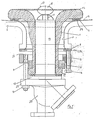
- Fig. 1 is a repair kit for the bottom opening of a Chemical container together with the associated outlet valve in the schematic Longitudinal section shown.
- the bottom of the container is with the Reference number 7 marked.
- the in the tank bottom 7 The opening provided includes an outlet 11. Inside is the container and outlet 11 with an enamel layer 12 Mistake.
- a repair socket 1 is inserted inside the container.
- the repair nozzle is supported opposite the container bottom 7 1 via a sealing ring 6.
- the with the container medium in Contact coming surface of the repair port 1 is also enamelled (enamel layer 13).
- a tubular fitting glass fiber reinforced PTFE used. This serves for longitudinally movable recording of one with one not shown axial drive on the one hand and with a Valve body 15 on the other hand connected valve stem 16, the interior end of the molding 14 a the Valve body 15 assigned to valve seat 17 (see FIG. 2) includes.
- clamping bolt 9 is in threaded bores 22 of the clamping ring 3 screwed. With her opposite At the end they extend through corresponding holes on Pipe connection 20 or on a flange 23 formed there through it.
- the definition of the pipe connection 20 and thus also of the fitting 14 is carried out by the clamping bolt 9 screw-on clamping nuts 10.
- the definition of the repair socket 1 within the Exhaust port 11 is done by clamping screws 5, which by the Clamping ring 3 are screwed under the plant lower end of the outlet port 11, namely under Interposition of a support ring 2. There are at least three Tensioning screws evenly distributed over the circumference 5 provided.
- the sealing ring 6 is a known component, which comprises a corrugated ring 24.
- the corresponding seal is manufactured by the applicant and under the name "Pfaudler AF 2000" distributed.
- the reference numeral 8 is the outside of the container or in FIG. 1 lower end of the outlet 11 marked.
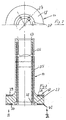
- Fig. 2 shows the tubular fitting 14 in longitudinal section. From this it can be seen that within the wall of the Molding 14 several, in particular at least three arranged uniformly over the circumference and in Reinforcing inserts extending in the longitudinal direction of the tube, here Glass rods 25 are provided. The glass rods 25 are inside corresponding axial bores 26 can be placed. You leave insert into these holes through insertion openings 27, the on the opposite side of the valve seat 17 of the Fitting 14 are arranged. After installing the glass rods 25 are the insertion openings 27 by a common Locking ring 28 sealed to the outside.
- the one Form 14 associated ring flange 18 has washer-shaped reinforcing inserts 29, 30, namely preferably made of graphite. These reinforcing inserts 29, 30 each extend just below the two flat sides of the ring flange 18 and over its circumference. This construction replaces separate ring flange seals, d. H. Ring seals between the ring flange 18 and the container neck 1 on the one hand and the ring flange 18 and the pipe connection 20 on the other hand.
- the Reinforcing inserts are elongated and in essentially over the entire length of the tubular fitting 14 extend.
- the receiving openings for the Reinforcing inserts e.g. B. glass rods, according to the Manufacture of the molded piece, e.g. B. by means of suitable Drilling tools.
- Reinforcing inserts during manufacture d. H. when molding to integrate the fittings 14.
Landscapes
- Engineering & Computer Science (AREA)
- Mechanical Engineering (AREA)
- General Engineering & Computer Science (AREA)
- Chemical & Material Sciences (AREA)
- Composite Materials (AREA)
- Valve Housings (AREA)
- Check Valves (AREA)
- Sewage (AREA)
- Quick-Acting Or Multi-Walled Pipe Joints (AREA)
Priority Applications (3)
| Application Number | Priority Date | Filing Date | Title |
|---|---|---|---|
| EP97114227A EP0908656B1 (fr) | 1997-08-18 | 1997-08-18 | Objet tubulaire utilisé comme siège de soupape |
| DE59708444T DE59708444D1 (de) | 1997-08-18 | 1997-08-18 | Rohrförmiges Formstück zur Definition eines Ventilsitzes |
| AT97114227T ATE225917T1 (de) | 1997-08-18 | 1997-08-18 | Rohrförmiges formstück zur definition eines ventilsitzes |
Applications Claiming Priority (1)
| Application Number | Priority Date | Filing Date | Title |
|---|---|---|---|
| EP97114227A EP0908656B1 (fr) | 1997-08-18 | 1997-08-18 | Objet tubulaire utilisé comme siège de soupape |
Publications (2)
| Publication Number | Publication Date |
|---|---|
| EP0908656A1 true EP0908656A1 (fr) | 1999-04-14 |
| EP0908656B1 EP0908656B1 (fr) | 2002-10-09 |
Family
ID=8227232
Family Applications (1)
| Application Number | Title | Priority Date | Filing Date |
|---|---|---|---|
| EP97114227A Expired - Lifetime EP0908656B1 (fr) | 1997-08-18 | 1997-08-18 | Objet tubulaire utilisé comme siège de soupape |
Country Status (3)
| Country | Link |
|---|---|
| EP (1) | EP0908656B1 (fr) |
| AT (1) | ATE225917T1 (fr) |
| DE (1) | DE59708444D1 (fr) |
Cited By (1)
| Publication number | Priority date | Publication date | Assignee | Title |
|---|---|---|---|---|
| CN114719048A (zh) * | 2022-04-17 | 2022-07-08 | 江苏金晟元特种阀门股份有限公司 | 一种氟塑料全衬隔膜阀 |
Citations (6)
| Publication number | Priority date | Publication date | Assignee | Title |
|---|---|---|---|---|
| FR962395A (fr) * | 1950-06-09 | |||
| FR1385915A (fr) * | 1964-03-06 | 1965-01-15 | Tubes plastiques rigides et à flexibilité réduite | |
| GB1397432A (en) * | 1972-08-17 | 1975-06-11 | Oldham Seals Ltd | Flanged hose end |
| GB2100818A (en) * | 1981-06-17 | 1983-01-06 | Bailey Bros | Drain rods |
| JPH0211990A (ja) * | 1988-06-29 | 1990-01-17 | Nitta Mua Co:Kk | 合成樹脂製管継手及びその製造方法 |
| JPH08312843A (ja) * | 1995-05-19 | 1996-11-26 | Nippon Petrochem Co Ltd | 既設配管の補修用パイプおよびそれを用いる補修方法 |
-
1997
- 1997-08-18 AT AT97114227T patent/ATE225917T1/de not_active IP Right Cessation
- 1997-08-18 DE DE59708444T patent/DE59708444D1/de not_active Expired - Lifetime
- 1997-08-18 EP EP97114227A patent/EP0908656B1/fr not_active Expired - Lifetime
Patent Citations (6)
| Publication number | Priority date | Publication date | Assignee | Title |
|---|---|---|---|---|
| FR962395A (fr) * | 1950-06-09 | |||
| FR1385915A (fr) * | 1964-03-06 | 1965-01-15 | Tubes plastiques rigides et à flexibilité réduite | |
| GB1397432A (en) * | 1972-08-17 | 1975-06-11 | Oldham Seals Ltd | Flanged hose end |
| GB2100818A (en) * | 1981-06-17 | 1983-01-06 | Bailey Bros | Drain rods |
| JPH0211990A (ja) * | 1988-06-29 | 1990-01-17 | Nitta Mua Co:Kk | 合成樹脂製管継手及びその製造方法 |
| JPH08312843A (ja) * | 1995-05-19 | 1996-11-26 | Nippon Petrochem Co Ltd | 既設配管の補修用パイプおよびそれを用いる補修方法 |
Non-Patent Citations (2)
| Title |
|---|
| DATABASE WPI Week 9009, Derwent World Patents Index; AN 90-061577, XP002052514 * |
| DATABASE WPI Week 9706, Derwent World Patents Index; AN 97-063293, XP002052515 * |
Cited By (2)
| Publication number | Priority date | Publication date | Assignee | Title |
|---|---|---|---|---|
| CN114719048A (zh) * | 2022-04-17 | 2022-07-08 | 江苏金晟元特种阀门股份有限公司 | 一种氟塑料全衬隔膜阀 |
| CN114719048B (zh) * | 2022-04-17 | 2023-10-03 | 江苏金晟元特种阀门股份有限公司 | 一种氟塑料全衬隔膜阀 |
Also Published As
| Publication number | Publication date |
|---|---|
| ATE225917T1 (de) | 2002-10-15 |
| DE59708444D1 (de) | 2002-11-14 |
| EP0908656B1 (fr) | 2002-10-09 |
Similar Documents
| Publication | Publication Date | Title |
|---|---|---|
| DE69210719T2 (de) | Durch Zusammendrücken lösbare Schnellverbindung | |
| DE102010049838A1 (de) | Formprozess für Auskleidung mit geteiltem Ansatzrohrübergangsstück | |
| AT397843B (de) | Übergangsstück aus kunststoff zum verbinden von kunststoffrohren mit armaturen oder rohren aus metallischen werkstoffen | |
| DE102012215977A1 (de) | Sanitär-Einhebel-Waschtischarmatur | |
| EP0745203B1 (fr) | Procede et pieces prefabriquees pour la realisation de derivations sur des tuyauteries | |
| EP2496871B1 (fr) | Système de raccordement, distributeur, système de conduites et système de montage en déport de conduites | |
| EP0908656B1 (fr) | Objet tubulaire utilisé comme siège de soupape | |
| EP0458076B1 (fr) | Distributeur pour branchement de tuyaux parcourus par au moins un fluide | |
| DE102017119704A1 (de) | Leitungskupplung und Behälter hiermit | |
| DE102008051303A1 (de) | Verschlusskupplung | |
| DE3141032A1 (de) | Rohrkupplung | |
| DE3346141C1 (de) | Anschlussverbindungseinheit | |
| DE102007031961A1 (de) | Behälterbehandlungsmaschine und Förderleitungsabschnitt | |
| DE202019104006U1 (de) | Modularer Verteiler für Rohrinstallationen | |
| DE3231950C2 (fr) | ||
| DE202006010374U1 (de) | Kugelhahn | |
| DE19536300C1 (de) | Wärmetauscher | |
| DE102005008398B4 (de) | Anbohrarmatur für Kunststoffrohre und Verfahren zum Anschließen einer Anbohrarmatur | |
| AT500163A2 (de) | Fluid-verteiler | |
| EP1128112A1 (fr) | Bride de fixation pour un tuyau | |
| DE102020123725B4 (de) | Filtereinheit zur Aufnahme einer Filterkartusche | |
| EP1271038A1 (fr) | Raccord vissé pour tubes | |
| EP0921343A2 (fr) | Joint torique | |
| DE102020109108B4 (de) | System zur Rohrverbindung | |
| DE29919536U1 (de) | Ventil, insbesondere für nahrungsmittelverarbeitende und kosmetische Anlagen |
Legal Events
| Date | Code | Title | Description |
|---|---|---|---|
| PUAI | Public reference made under article 153(3) epc to a published international application that has entered the european phase |
Free format text: ORIGINAL CODE: 0009012 |
|
| 17P | Request for examination filed |
Effective date: 19980929 |
|
| AK | Designated contracting states |
Kind code of ref document: A1 Designated state(s): AT BE CH DE DK ES FI FR GB GR IE IT LI LU MC NL PT SE |
|
| AKX | Designation fees paid |
Free format text: AT BE CH DE DK ES FI FR GB GR IE IT LI LU MC NL PT SE |
|
| GRAG | Despatch of communication of intention to grant |
Free format text: ORIGINAL CODE: EPIDOS AGRA |
|
| 17Q | First examination report despatched |
Effective date: 20011121 |
|
| GRAG | Despatch of communication of intention to grant |
Free format text: ORIGINAL CODE: EPIDOS AGRA |
|
| GRAH | Despatch of communication of intention to grant a patent |
Free format text: ORIGINAL CODE: EPIDOS IGRA |
|
| GRAH | Despatch of communication of intention to grant a patent |
Free format text: ORIGINAL CODE: EPIDOS IGRA |
|
| GRAA | (expected) grant |
Free format text: ORIGINAL CODE: 0009210 |
|
| AK | Designated contracting states |
Kind code of ref document: B1 Designated state(s): AT BE CH DE DK ES FI FR GB GR IE IT LI LU MC NL PT SE |
|
| PG25 | Lapsed in a contracting state [announced via postgrant information from national office to epo] |
Ref country code: NL Free format text: LAPSE BECAUSE OF FAILURE TO SUBMIT A TRANSLATION OF THE DESCRIPTION OR TO PAY THE FEE WITHIN THE PRESCRIBED TIME-LIMIT Effective date: 20021009 Ref country code: IE Free format text: LAPSE BECAUSE OF FAILURE TO SUBMIT A TRANSLATION OF THE DESCRIPTION OR TO PAY THE FEE WITHIN THE PRESCRIBED TIME-LIMIT Effective date: 20021009 Ref country code: GR Free format text: LAPSE BECAUSE OF FAILURE TO SUBMIT A TRANSLATION OF THE DESCRIPTION OR TO PAY THE FEE WITHIN THE PRESCRIBED TIME-LIMIT Effective date: 20021009 Ref country code: GB Free format text: LAPSE BECAUSE OF FAILURE TO SUBMIT A TRANSLATION OF THE DESCRIPTION OR TO PAY THE FEE WITHIN THE PRESCRIBED TIME-LIMIT Effective date: 20021009 Ref country code: FI Free format text: LAPSE BECAUSE OF FAILURE TO SUBMIT A TRANSLATION OF THE DESCRIPTION OR TO PAY THE FEE WITHIN THE PRESCRIBED TIME-LIMIT Effective date: 20021009 |
|
| REF | Corresponds to: |
Ref document number: 225917 Country of ref document: AT Date of ref document: 20021015 Kind code of ref document: T |
|
| REG | Reference to a national code |
Ref country code: GB Ref legal event code: FG4D Free format text: NOT ENGLISH |
|
| RIN1 | Information on inventor provided before grant (corrected) |
Inventor name: WEBER, STEFAN Inventor name: REINEMUTH, JUERGEN, DR.-ING. Inventor name: SCHERTZ, REINHART |
|
| REG | Reference to a national code |
Ref country code: CH Ref legal event code: EP |
|
| REG | Reference to a national code |
Ref country code: IE Ref legal event code: FG4D Free format text: GERMAN |
|
| REF | Corresponds to: |
Ref document number: 59708444 Country of ref document: DE Date of ref document: 20021114 |
|
| REG | Reference to a national code |
Ref country code: CH Ref legal event code: NV Representative=s name: TROESCH SCHEIDEGGER WERNER AG |
|
| PG25 | Lapsed in a contracting state [announced via postgrant information from national office to epo] |
Ref country code: SE Free format text: LAPSE BECAUSE OF FAILURE TO SUBMIT A TRANSLATION OF THE DESCRIPTION OR TO PAY THE FEE WITHIN THE PRESCRIBED TIME-LIMIT Effective date: 20030109 Ref country code: PT Free format text: LAPSE BECAUSE OF FAILURE TO SUBMIT A TRANSLATION OF THE DESCRIPTION OR TO PAY THE FEE WITHIN THE PRESCRIBED TIME-LIMIT Effective date: 20030109 Ref country code: DK Free format text: LAPSE BECAUSE OF FAILURE TO SUBMIT A TRANSLATION OF THE DESCRIPTION OR TO PAY THE FEE WITHIN THE PRESCRIBED TIME-LIMIT Effective date: 20030109 |
|
| NLV1 | Nl: lapsed or annulled due to failure to fulfill the requirements of art. 29p and 29m of the patents act | ||
| GBV | Gb: ep patent (uk) treated as always having been void in accordance with gb section 77(7)/1977 [no translation filed] |
Effective date: 20021009 |
|
| PG25 | Lapsed in a contracting state [announced via postgrant information from national office to epo] |
Ref country code: ES Free format text: LAPSE BECAUSE OF FAILURE TO SUBMIT A TRANSLATION OF THE DESCRIPTION OR TO PAY THE FEE WITHIN THE PRESCRIBED TIME-LIMIT Effective date: 20030429 |
|
| ET | Fr: translation filed | ||
| REG | Reference to a national code |
Ref country code: IE Ref legal event code: FD4D Ref document number: 0908656E Country of ref document: IE |
|
| PLBE | No opposition filed within time limit |
Free format text: ORIGINAL CODE: 0009261 |
|
| STAA | Information on the status of an ep patent application or granted ep patent |
Free format text: STATUS: NO OPPOSITION FILED WITHIN TIME LIMIT |
|
| PG25 | Lapsed in a contracting state [announced via postgrant information from national office to epo] |
Ref country code: LU Free format text: LAPSE BECAUSE OF NON-PAYMENT OF DUE FEES Effective date: 20030818 Ref country code: AT Free format text: LAPSE BECAUSE OF NON-PAYMENT OF DUE FEES Effective date: 20030818 |
|
| PG25 | Lapsed in a contracting state [announced via postgrant information from national office to epo] |
Ref country code: MC Free format text: LAPSE BECAUSE OF NON-PAYMENT OF DUE FEES Effective date: 20030831 Ref country code: BE Free format text: LAPSE BECAUSE OF NON-PAYMENT OF DUE FEES Effective date: 20030831 |
|
| 26N | No opposition filed |
Effective date: 20030710 |
|
| BERE | Be: lapsed |
Owner name: *PFAUDLER WERKE G.M.B.H. Effective date: 20030831 |
|
| PGFP | Annual fee paid to national office [announced via postgrant information from national office to epo] |
Ref country code: FR Payment date: 20040804 Year of fee payment: 8 |
|
| PGFP | Annual fee paid to national office [announced via postgrant information from national office to epo] |
Ref country code: DE Payment date: 20040831 Year of fee payment: 8 |
|
| PGFP | Annual fee paid to national office [announced via postgrant information from national office to epo] |
Ref country code: CH Payment date: 20040914 Year of fee payment: 8 |
|
| PG25 | Lapsed in a contracting state [announced via postgrant information from national office to epo] |
Ref country code: DE Free format text: LAPSE BECAUSE OF THE APPLICANT RENOUNCES Effective date: 20041112 |
|
| PG25 | Lapsed in a contracting state [announced via postgrant information from national office to epo] |
Ref country code: IT Free format text: LAPSE BECAUSE OF NON-PAYMENT OF DUE FEES Effective date: 20050818 |
|
| PG25 | Lapsed in a contracting state [announced via postgrant information from national office to epo] |
Ref country code: LI Free format text: LAPSE BECAUSE OF NON-PAYMENT OF DUE FEES Effective date: 20050831 Ref country code: CH Free format text: LAPSE BECAUSE OF NON-PAYMENT OF DUE FEES Effective date: 20050831 |
|
| REG | Reference to a national code |
Ref country code: CH Ref legal event code: PL |
|
| PG25 | Lapsed in a contracting state [announced via postgrant information from national office to epo] |
Ref country code: FR Free format text: LAPSE BECAUSE OF NON-PAYMENT OF DUE FEES Effective date: 20060428 |
|
| REG | Reference to a national code |
Ref country code: FR Ref legal event code: ST Effective date: 20060428 |