EP0921343A2 - Joint torique - Google Patents
Joint torique Download PDFInfo
- Publication number
- EP0921343A2 EP0921343A2 EP19980119091 EP98119091A EP0921343A2 EP 0921343 A2 EP0921343 A2 EP 0921343A2 EP 19980119091 EP19980119091 EP 19980119091 EP 98119091 A EP98119091 A EP 98119091A EP 0921343 A2 EP0921343 A2 EP 0921343A2
- Authority
- EP
- European Patent Office
- Prior art keywords
- sealing ring
- recesses
- ring
- ring according
- ring element
- Prior art date
- Legal status (The legal status is an assumption and is not a legal conclusion. Google has not performed a legal analysis and makes no representation as to the accuracy of the status listed.)
- Withdrawn
Links
Images
Classifications
-
- F—MECHANICAL ENGINEERING; LIGHTING; HEATING; WEAPONS; BLASTING
- F16—ENGINEERING ELEMENTS AND UNITS; GENERAL MEASURES FOR PRODUCING AND MAINTAINING EFFECTIVE FUNCTIONING OF MACHINES OR INSTALLATIONS; THERMAL INSULATION IN GENERAL
- F16L—PIPES; JOINTS OR FITTINGS FOR PIPES; SUPPORTS FOR PIPES, CABLES OR PROTECTIVE TUBING; MEANS FOR THERMAL INSULATION IN GENERAL
- F16L23/00—Flanged joints
- F16L23/16—Flanged joints characterised by the sealing means
- F16L23/18—Flanged joints characterised by the sealing means the sealing means being rings
-
- F—MECHANICAL ENGINEERING; LIGHTING; HEATING; WEAPONS; BLASTING
- F16—ENGINEERING ELEMENTS AND UNITS; GENERAL MEASURES FOR PRODUCING AND MAINTAINING EFFECTIVE FUNCTIONING OF MACHINES OR INSTALLATIONS; THERMAL INSULATION IN GENERAL
- F16J—PISTONS; CYLINDERS; SEALINGS
- F16J15/00—Sealings
- F16J15/02—Sealings between relatively-stationary surfaces
- F16J15/06—Sealings between relatively-stationary surfaces with solid packing compressed between sealing surfaces
- F16J15/061—Sealings between relatively-stationary surfaces with solid packing compressed between sealing surfaces with positioning means
Definitions
- the present invention relates to a sealing ring according to the preamble of Claim 1.
- Transitional connections necessary. These transition connections usually have fittings that, for example, with a flange adapter are provided. The flange surfaces of two flange adapters to be connected to each other, are interposed with a sealing ring Plant brought.
- the sealing ring must usually be designed so that it has the flange cross-section covers well, i.e. if possible from the inside diameter to Outside diameter of the flange is sufficient. This should create a fluid tight connection guaranteed by two adjacent flanges with an intermediate seal be.
- Flange rings are provided for connecting the pipes, which are pushed over the flange adapter and screwed together. As a result, the contact pressure required for a fluid-tight connection can be applied to the seal between the flange washers.
- the sealing ring slips and as follows the flange ring cross section no longer covers enough. That leads to different Surface pressure in the flange ring area of the flange adapter, what in turn can lead to leakage.
- a self-centering template ring which serves a spiral-shaped sealing ring between two pipe flanges to center.
- the sealing ring is inside the template ring arranged.
- the template ring itself is provided with eight concave recesses, in which the fastening screws can be received.
- the Stencil ring is designed so that certain dimensional differences of the flanges and the screws can be accommodated.
- To position the The template ring has two tabs on the outer circumference. Except that a separate template ring is used to position the sealing ring the stencil ring is only suitable for different purposes Hole pattern standards.
- the present invention is based on the explained prior art the task of proposing a sealing ring that can be used universally.
- the sealing ring is proposed to manufacture from two essentially circular ring elements, the inner ring element being chemical with respect to the medium to be sealed should be constant.
- Such a sealing ring can be very universal use because the two ring elements are made of different materials and can be optimally adapted to your task.
- outer ring element made of an elastic material preferably of a Elastomer and the inner ring element preferably made of a fluorocarbon manufacture.
- An inner ring element made of fluorocarbon has the advantage that it has a smooth surface and the inner diameter within narrow tolerances can be manufactured.
- the sealing ring in question is to be arranged with two Pipes provided with flange elements.
- Flange rings are provided, which are pushed over the flange adapter and by means of Screws are connected. Because such pipes as well Flange elements and flange rings are well known, was based on their representation waived.
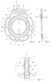
- the sealing ring which is not drawn to scale, essentially consists of two annular ring elements 1, 2.
- the inner ring element 1 has a slot along the outer circumference, in which the outer ring element 2 is partially included.
- the outer ring element 2 is preferred made of an elastomer while the inner ring member 1 is preferred is made of a fluorocarbon such as PTFE (polytetrafluoroethylene).
- PTFE polytetrafluoroethylene
- the inner ring element 1 should be in relation to the medium to be sealed be chemically stable.
- the outer ring element 2 has two circular thickenings 4A, which in corresponding Recesses 4B of the inner ring element 1 are received (Fig. 3).
- the outer ring element 2 in the peripheral area with a plurality of recesses A, B, C for different hole pattern standards.
- These recesses A, B, C are destined for at least the connecting screws of a flange connection arrangement to include partially form-fitting.
- This sealing ring shows a total of twenty recesses for three different hole pattern standards on. The number of recesses depends on the dimension of the sealing ring. So eight recesses with the reference symbol A for a hole pattern according to the ISO standard. With B there are eight recesses for a hole pattern Japanese standard (JIS).
- JIS Japanese standard
- the sealing ring has a tongue 3 into which one hole A1, B1, C1 is inserted for each different standardization.
- This tongue 3 has the advantage that it simplifies the handling of the sealing ring.
- the sealing ring can be inserted by inserting a screw the corresponding hole A1, B1, C1 in the tongue 3 are fixed in its position.
- To assign the recesses A, B, C to the corresponding hole pattern standardization To simplify, one hole each A1, B1, C1 and a recess A, B, C labeled per hole pattern standardization.
- FIG. 3 which shows an enlarged section of FIG. 2, the Connection between the inner and outer ring element 1, 2 can be seen.
- the two thickenings 4A of the outer surface can be seen from this illustration Ring element 2, which in the corresponding recesses 4B in the Slit 5 of the inner ring member 1 are added.
- the thickenings 4A of the outer ring element 2 continue on both sides of the inner ring element 1, so that the latter is provided with two annular projections 4C.
- elevations 4C locally cause a high surface pressure, so that a good sealing effect of the relatively inelastic material (PTFE) of the inner ring element 1 is favored.
- PTFE relatively inelastic material
- the described sealing ring opens up a wide range of possible applications covered in the simplest way.
- a sealing ring designed in this way can be arranged simply, quickly and safely between flange elements with different hole pattern standards.
- the sealing ring is suitable for a wide variety of sealing tasks due to the two-part design, since the two ring elements are made of different materials and can therefore be optimally adapted to their task.
- the fact that the inner ring element is made of a material which is chemically stable with respect to the medium to be sealed means that the sealing ring has the further advantage that there is no contamination of the fluid flowing through the pipes and that the sealing ring is not attacked by the fluid flowing through.
- Another advantage is that the smooth surface of the inner ring element and its close tolerance with respect to the inner diameter ensure a largely dead space-free connection of two pipes by closely fitting the inside of the pipes to the inside of the sealing ring. As a result, bacteria can hardly grow, which is crucial for so-called Is high-purity "applications.
Applications Claiming Priority (2)
| Application Number | Priority Date | Filing Date | Title |
|---|---|---|---|
| CH279797 | 1997-12-04 | ||
| CH279797 | 1997-12-04 |
Publications (1)
| Publication Number | Publication Date |
|---|---|
| EP0921343A2 true EP0921343A2 (fr) | 1999-06-09 |
Family
ID=4241807
Family Applications (1)
| Application Number | Title | Priority Date | Filing Date |
|---|---|---|---|
| EP19980119091 Withdrawn EP0921343A2 (fr) | 1997-12-04 | 1998-10-09 | Joint torique |
Country Status (1)
| Country | Link |
|---|---|
| EP (1) | EP0921343A2 (fr) |
Cited By (5)
| Publication number | Priority date | Publication date | Assignee | Title |
|---|---|---|---|---|
| US6260854B1 (en) | 1998-10-09 | 2001-07-17 | Georg Fischer Rohleitungssysteme Ag | Flat gasket ring |
| EP1772179A2 (fr) * | 2005-10-07 | 2007-04-11 | WAIWELDAI Anlagentechnik GmbH | Flasque de fixation |
| EP1800042A2 (fr) * | 2004-09-09 | 2007-06-27 | BS & B Safety Systems Limited | Adaptateur a bride |
| DE102007005300A1 (de) | 2007-02-02 | 2008-08-14 | Audi Ag | Dichtungsring |
| EP2472159A1 (fr) * | 2010-12-29 | 2012-07-04 | Pamargan Products Limited | Scellement évasé |
-
1998
- 1998-10-09 EP EP19980119091 patent/EP0921343A2/fr not_active Withdrawn
Cited By (10)
| Publication number | Priority date | Publication date | Assignee | Title |
|---|---|---|---|---|
| US6260854B1 (en) | 1998-10-09 | 2001-07-17 | Georg Fischer Rohleitungssysteme Ag | Flat gasket ring |
| EP1800042A2 (fr) * | 2004-09-09 | 2007-06-27 | BS & B Safety Systems Limited | Adaptateur a bride |
| EP1800042A4 (fr) * | 2004-09-09 | 2009-04-15 | Bs & B Safety Systems Ltd | Adaptateur a bride |
| US9810333B2 (en) | 2004-09-09 | 2017-11-07 | Bs&B Safety Systems Limited | Flange adapter |
| EP1772179A2 (fr) * | 2005-10-07 | 2007-04-11 | WAIWELDAI Anlagentechnik GmbH | Flasque de fixation |
| EP1772179A3 (fr) * | 2005-10-07 | 2011-01-05 | WAIWELDAI Anlagentechnik GmbH | Flasque de fixation |
| DE102007005300A1 (de) | 2007-02-02 | 2008-08-14 | Audi Ag | Dichtungsring |
| DE102007005300B4 (de) * | 2007-02-02 | 2010-06-02 | Audi Ag | Dichtungsring |
| EP2472159A1 (fr) * | 2010-12-29 | 2012-07-04 | Pamargan Products Limited | Scellement évasé |
| WO2012090171A3 (fr) * | 2010-12-29 | 2012-11-08 | Pamargan Products Ltd | Joint d'étanchéité de rebord |
Similar Documents
| Publication | Publication Date | Title |
|---|---|---|
| DE60108740T2 (de) | Verbesserter dichtring | |
| EP0992717B1 (fr) | Anneau d'étanchéité plat | |
| EP0909915B1 (fr) | Joint d'étanchéité pour moyens de raccordement | |
| DE2319999A1 (de) | Verbinder | |
| EP0665402A1 (fr) | Connecteur à fiche pour systèmes de conduites sous pression | |
| EP1722146B1 (fr) | Dispositif de connexion pour tuyaux avec élément annulaire | |
| EP0483751A1 (fr) | Système d'assemblage | |
| DE4001275A1 (de) | Zwischen einer metallrohrleitung geringen durchmessers und einem flexiblen schlauch eingebrachter konnektor | |
| DE3612689A1 (de) | Schnellverbindungsarmatur | |
| DE3032532A1 (de) | Rohrleitungsmolch | |
| DE19542463B4 (de) | Rohrkupplung | |
| EP0921343A2 (fr) | Joint torique | |
| DE2832439A1 (de) | Ringdichtung, insbesondere fuer absperrorgane mit kugelfoermigem absperrkoerper | |
| EP0491984A1 (fr) | Ensemble de raccord pour deux systèmes fluides | |
| WO2003052311A1 (fr) | Raccord de tuyauterie | |
| DE19723594A1 (de) | Rohrverbinder | |
| WO1982003440A1 (fr) | Raccordement etanche de tubes en matiere plastique resistant aux forces de poussee | |
| EP0879982B1 (fr) | Accouplement pour tuyau flexible | |
| DE10118955C2 (de) | Rohrverbindung | |
| DE19712171C1 (de) | Klemmverbinder | |
| CH623392A5 (fr) | ||
| EP2023027A2 (fr) | Jonction tubulaire | |
| EP0971120B1 (fr) | Elément de raccordement pour une conduite à haute pression | |
| DE10112548C2 (de) | Rohrverbindung mit Fitting | |
| WO1986007428A1 (fr) | Systeme de fermeture et de regulation avec clapet |
Legal Events
| Date | Code | Title | Description |
|---|---|---|---|
| PUAI | Public reference made under article 153(3) epc to a published international application that has entered the european phase |
Free format text: ORIGINAL CODE: 0009012 |
|
| AK | Designated contracting states |
Kind code of ref document: A2 Designated state(s): AT BE CH CY DE DK ES FI FR GB GR IE IT LI LU MC NL PT SE |
|
| AX | Request for extension of the european patent |
Free format text: AL;LT;LV;MK;RO;SI |
|
| STAA | Information on the status of an ep patent application or granted ep patent |
Free format text: STATUS: THE APPLICATION HAS BEEN WITHDRAWN |
|
| 18W | Application withdrawn |
Withdrawal date: 19990701 |