EP0921343A2 - Ring seal - Google Patents
Ring seal Download PDFInfo
- Publication number
- EP0921343A2 EP0921343A2 EP19980119091 EP98119091A EP0921343A2 EP 0921343 A2 EP0921343 A2 EP 0921343A2 EP 19980119091 EP19980119091 EP 19980119091 EP 98119091 A EP98119091 A EP 98119091A EP 0921343 A2 EP0921343 A2 EP 0921343A2
- Authority
- EP
- European Patent Office
- Prior art keywords
- sealing ring
- recesses
- ring
- ring according
- ring element
- Prior art date
- Legal status (The legal status is an assumption and is not a legal conclusion. Google has not performed a legal analysis and makes no representation as to the accuracy of the status listed.)
- Withdrawn
Links
Images
Classifications
-
- F—MECHANICAL ENGINEERING; LIGHTING; HEATING; WEAPONS; BLASTING
- F16—ENGINEERING ELEMENTS AND UNITS; GENERAL MEASURES FOR PRODUCING AND MAINTAINING EFFECTIVE FUNCTIONING OF MACHINES OR INSTALLATIONS; THERMAL INSULATION IN GENERAL
- F16L—PIPES; JOINTS OR FITTINGS FOR PIPES; SUPPORTS FOR PIPES, CABLES OR PROTECTIVE TUBING; MEANS FOR THERMAL INSULATION IN GENERAL
- F16L23/00—Flanged joints
- F16L23/16—Flanged joints characterised by the sealing means
- F16L23/18—Flanged joints characterised by the sealing means the sealing means being rings
-
- F—MECHANICAL ENGINEERING; LIGHTING; HEATING; WEAPONS; BLASTING
- F16—ENGINEERING ELEMENTS AND UNITS; GENERAL MEASURES FOR PRODUCING AND MAINTAINING EFFECTIVE FUNCTIONING OF MACHINES OR INSTALLATIONS; THERMAL INSULATION IN GENERAL
- F16J—PISTONS; CYLINDERS; SEALINGS
- F16J15/00—Sealings
- F16J15/02—Sealings between relatively-stationary surfaces
- F16J15/06—Sealings between relatively-stationary surfaces with solid packing compressed between sealing surfaces
- F16J15/061—Sealings between relatively-stationary surfaces with solid packing compressed between sealing surfaces with positioning means
Definitions
- the present invention relates to a sealing ring according to the preamble of Claim 1.
- Transitional connections necessary. These transition connections usually have fittings that, for example, with a flange adapter are provided. The flange surfaces of two flange adapters to be connected to each other, are interposed with a sealing ring Plant brought.
- the sealing ring must usually be designed so that it has the flange cross-section covers well, i.e. if possible from the inside diameter to Outside diameter of the flange is sufficient. This should create a fluid tight connection guaranteed by two adjacent flanges with an intermediate seal be.
- Flange rings are provided for connecting the pipes, which are pushed over the flange adapter and screwed together. As a result, the contact pressure required for a fluid-tight connection can be applied to the seal between the flange washers.
- the sealing ring slips and as follows the flange ring cross section no longer covers enough. That leads to different Surface pressure in the flange ring area of the flange adapter, what in turn can lead to leakage.
- a self-centering template ring which serves a spiral-shaped sealing ring between two pipe flanges to center.
- the sealing ring is inside the template ring arranged.
- the template ring itself is provided with eight concave recesses, in which the fastening screws can be received.
- the Stencil ring is designed so that certain dimensional differences of the flanges and the screws can be accommodated.
- To position the The template ring has two tabs on the outer circumference. Except that a separate template ring is used to position the sealing ring the stencil ring is only suitable for different purposes Hole pattern standards.
- the present invention is based on the explained prior art the task of proposing a sealing ring that can be used universally.
- the sealing ring is proposed to manufacture from two essentially circular ring elements, the inner ring element being chemical with respect to the medium to be sealed should be constant.
- Such a sealing ring can be very universal use because the two ring elements are made of different materials and can be optimally adapted to your task.
- outer ring element made of an elastic material preferably of a Elastomer and the inner ring element preferably made of a fluorocarbon manufacture.
- An inner ring element made of fluorocarbon has the advantage that it has a smooth surface and the inner diameter within narrow tolerances can be manufactured.
- the sealing ring in question is to be arranged with two Pipes provided with flange elements.
- Flange rings are provided, which are pushed over the flange adapter and by means of Screws are connected. Because such pipes as well Flange elements and flange rings are well known, was based on their representation waived.
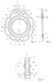
- the sealing ring which is not drawn to scale, essentially consists of two annular ring elements 1, 2.
- the inner ring element 1 has a slot along the outer circumference, in which the outer ring element 2 is partially included.
- the outer ring element 2 is preferred made of an elastomer while the inner ring member 1 is preferred is made of a fluorocarbon such as PTFE (polytetrafluoroethylene).
- PTFE polytetrafluoroethylene
- the inner ring element 1 should be in relation to the medium to be sealed be chemically stable.
- the outer ring element 2 has two circular thickenings 4A, which in corresponding Recesses 4B of the inner ring element 1 are received (Fig. 3).
- the outer ring element 2 in the peripheral area with a plurality of recesses A, B, C for different hole pattern standards.
- These recesses A, B, C are destined for at least the connecting screws of a flange connection arrangement to include partially form-fitting.
- This sealing ring shows a total of twenty recesses for three different hole pattern standards on. The number of recesses depends on the dimension of the sealing ring. So eight recesses with the reference symbol A for a hole pattern according to the ISO standard. With B there are eight recesses for a hole pattern Japanese standard (JIS).
- JIS Japanese standard
- the sealing ring has a tongue 3 into which one hole A1, B1, C1 is inserted for each different standardization.
- This tongue 3 has the advantage that it simplifies the handling of the sealing ring.
- the sealing ring can be inserted by inserting a screw the corresponding hole A1, B1, C1 in the tongue 3 are fixed in its position.
- To assign the recesses A, B, C to the corresponding hole pattern standardization To simplify, one hole each A1, B1, C1 and a recess A, B, C labeled per hole pattern standardization.
- FIG. 3 which shows an enlarged section of FIG. 2, the Connection between the inner and outer ring element 1, 2 can be seen.
- the two thickenings 4A of the outer surface can be seen from this illustration Ring element 2, which in the corresponding recesses 4B in the Slit 5 of the inner ring member 1 are added.
- the thickenings 4A of the outer ring element 2 continue on both sides of the inner ring element 1, so that the latter is provided with two annular projections 4C.
- elevations 4C locally cause a high surface pressure, so that a good sealing effect of the relatively inelastic material (PTFE) of the inner ring element 1 is favored.
- PTFE relatively inelastic material
- the described sealing ring opens up a wide range of possible applications covered in the simplest way.
- a sealing ring designed in this way can be arranged simply, quickly and safely between flange elements with different hole pattern standards.
- the sealing ring is suitable for a wide variety of sealing tasks due to the two-part design, since the two ring elements are made of different materials and can therefore be optimally adapted to their task.
- the fact that the inner ring element is made of a material which is chemically stable with respect to the medium to be sealed means that the sealing ring has the further advantage that there is no contamination of the fluid flowing through the pipes and that the sealing ring is not attacked by the fluid flowing through.
- Another advantage is that the smooth surface of the inner ring element and its close tolerance with respect to the inner diameter ensure a largely dead space-free connection of two pipes by closely fitting the inside of the pipes to the inside of the sealing ring. As a result, bacteria can hardly grow, which is crucial for so-called Is high-purity "applications.
Abstract
Description
Die vorliegende Erfindung betrifft einen Dichtungsring nach dem Oberbegriff des
Anspruchs 1.The present invention relates to a sealing ring according to the preamble of
Bei der Verlegung von Rohrleitungen sind zwischen den einzelnen Rohrleitungsabschnitten Uebergangsverbindungen notwendig. Diese Uebergangsverbindungen weisen in der Regel Formstücke auf, die beispielsweise mit einem Flanschadapter versehen sind. Die Flanschflächen von zwei miteinander zu verbindenden Flanschadaptern, werden unter Zwischenschaltung eines Dichtungsringes miteinander in Anlage gebracht.When laying pipelines are between the individual pipe sections Transitional connections necessary. These transition connections usually have fittings that, for example, with a flange adapter are provided. The flange surfaces of two flange adapters to be connected to each other, are interposed with a sealing ring Plant brought.
Der Dichtungsring muss in der Regel so ausgebildet sein, dass er den Flanschflächenquerschnitt gut abdeckt, d.h. möglichst vom Innendurchmesser bis zum Aussendurchmesser des Flansches reicht. Damit sollte eine fluiddichte Verbindung von zwei aneinanderliegenden Flanschen mit zwischengeordneter Dichtung gewährleistet sein. Zum Verbinden der Rohrleitungen sind Flanschringe vorgesehen, welche über den Flanschadapter geschoben und miteinander verschraubt werden. Dadurch kann der für eine fluiddichte Verbindung erforderliche Anpressdruck auf die zwischen den Flanschscheiben liegende Dichtung aufgebracht werden. Bei der Montage kann es leicht vorkommen, dass der Dichtungsring verrutscht und als Folge den Flanschringquerschnitt nicht mehr genügend abdeckt. Das führt zu unterschiedlichen Flächenpressdrücken im Flanschringbereich des Flanschadapters, was wiederum zur Leckage führen kann.The sealing ring must usually be designed so that it has the flange cross-section covers well, i.e. if possible from the inside diameter to Outside diameter of the flange is sufficient. This should create a fluid tight connection guaranteed by two adjacent flanges with an intermediate seal be. Flange rings are provided for connecting the pipes, which are pushed over the flange adapter and screwed together. As a result, the contact pressure required for a fluid-tight connection can be applied to the seal between the flange washers. In the Assembly, it can easily happen that the sealing ring slips and as Follow the flange ring cross section no longer covers enough. That leads to different Surface pressure in the flange ring area of the flange adapter, what in turn can lead to leakage.
Aus der US 34 80 301 ist ein selbstzentrierender Schablonenring bekannt, welcher dazu dient, einen spiralförmig ausgebildeten Dichtungsring zwischen zwei Rohrflanschen zu zentrieren. Der Dichtungsring ist dabei innerhalb des Schablonenrings angeordnet. Der Schablonenring selber ist mit acht konkaven Ausnehmungen versehen, in welchen die Befestigungsschrauben aufgenommen werden können. Der Schablonenring ist so ausgelegt, dass gewisse Dimensionsunterschiede der Flansche und der Schrauben aufgenommen werden können. Zum Positionieren des Schablonenrings weist dieser am äusseren Umfang zwei Laschen auf. Abgesehen davon, dass zur Positionierung des Dichtrings ein separater Schablonenring eingesetzt werden muss, eignet sich der Schablonenring nur beschränkt für unterschiedliche Lochbild-Normungen.From US 34 80 301 a self-centering template ring is known, which serves a spiral-shaped sealing ring between two pipe flanges to center. The sealing ring is inside the template ring arranged. The template ring itself is provided with eight concave recesses, in which the fastening screws can be received. Of the Stencil ring is designed so that certain dimensional differences of the flanges and the screws can be accommodated. To position the The template ring has two tabs on the outer circumference. Except that a separate template ring is used to position the sealing ring the stencil ring is only suitable for different purposes Hole pattern standards.
Ausgehend vom erläuterten Stand der Technik stellt sich die vorliegende Erfindung die Aufgabe, einen Dichtungsring vorzuschlagen, der universell einsetzbar ist.The present invention is based on the explained prior art the task of proposing a sealing ring that can be used universally.
Diese Aufgabe wird durch den kennzeichnenden Teil des Anspruches 1 gelöst.
Weitere vorteilhafte Ausgestaltungen gehen aus den abhängigen Ansprüchen hervor.This object is solved by the characterizing part of
So wird in einem bevorzugten Ausführungsbeispiel vorgeschlagen, den Dichtungsring aus zwei im wesentlichen kreisringförmig gestalteten Ringelementen zu fertigen, wobei das innere Ringelement bezüglich des abzudichtenden Mediums chemisch beständig sein soll. Ein derartiger Dichtungsring lässt sich sehr universell einsetzen, da die beiden Ringelemente aus unterschiedlichen Materialien gefertigt und optimal an ihre Aufgabe angepasst werden können.In a preferred embodiment, the sealing ring is proposed to manufacture from two essentially circular ring elements, the inner ring element being chemical with respect to the medium to be sealed should be constant. Such a sealing ring can be very universal use because the two ring elements are made of different materials and can be optimally adapted to your task.
In einem weiteren, bevorzugten Ausführungsbeispiel wird vorgeschlagen, das äussere Ringelement aus einem elastischen Werkstoff, vorzugsweise aus einem Elastomer und das innere Ringelement vorzugsweise aus einem Fluorcarbon zu fertigen. Ein aus Fluorcarbon gefertigtes inneres Ringelement hat den Vorteil, dass es eine glatte Oberfläche besitzt und der Innendurchmesser innerhalb enger Toleranzen gefertigt werden kann.In a further preferred embodiment it is proposed that outer ring element made of an elastic material, preferably of a Elastomer and the inner ring element preferably made of a fluorocarbon manufacture. An inner ring element made of fluorocarbon has the advantage that it has a smooth surface and the inner diameter within narrow tolerances can be manufactured.
Anhand der beiliegenden Zeichnung wird ein bevorzugtes Ausführungsbeispiel der
Erfindung näher erläutert. In dieser Zeichnung zeigt:
Der hier zur Rede stehende Dichtungsring ist zur Anordnung zwischen zwei mit Flanschelementen versehenen Rohren vorgesehen. Zum Verbinden der Rohre sind Flanschringe vorgesehen, welche über den Flanschadapter geschoben und mittels Schrauben miteinander verbunden werden. Da derartige Rohre wie auch die Flanschelemente und Flanschringe hinreichend bekannt sind, wurde auf deren Darstellung verzichtet.The sealing ring in question is to be arranged with two Pipes provided with flange elements. To connect the pipes are Flange rings are provided, which are pushed over the flange adapter and by means of Screws are connected. Because such pipes as well Flange elements and flange rings are well known, was based on their representation waived.
Der nicht massstabsgetreu wiedergegebene Dichtungsring besteht aus zwei im wesentlichen
kreisringförmig gestalteten Ringelementen 1, 2. Das innere Ringelement
1 weist entlang des äusseren Umfangs einen Schlitz auf, in dem das äussere Ringelement
2 teilweise aufgenommen ist. Das äussere Ringelement 2 ist vorzugsweise
aus einem Elastomer gefertigt währenddem das innere Ringelement 1 vorzugsweise
aus einem Fluorcarbon wie beispielsweise PTFE (Polytetrafluorethylen) gefertigt ist.
Jedenfalls soll das innere Ringelement 1 bezüglich des abzudichtenden Mediums
chemisch beständig sein. Um eine sichere und dichte Verbindung zwischen den
beiden Ringelementen 1, 2 zu erreichen, weist das äussere Ringelement 2 zwei
kreisringförmig verlaufende Verdickungen 4A auf, welche in korrespondierenden
Aussparungen 4B des inneren Ringelements 1 aufgenommen sind (Fig. 3).The sealing ring, which is not drawn to scale, essentially consists of two
Um ein und denselben Dichtungsring für Rohrverbindungen mit unterschiedlichen
Verbindungsschraubenanordnungen einsetzen zu können, ist das äussere Ringelement
2 im Umfangsbereich mit einer Mehrzahl von Ausnehmungen A, B, C für
unterschiedliche Lochbild-Normungen versehen. Diese Ausnehmungen A, B, C sind
dazu bestimmt, die Verbindungsschrauben einer Flanschanschlussanordnung mindestens
teilweise formschlüssig zu umfassen. Der vorliegende Dichtungsring weist
insgesamt zwanzig Ausnehmungen für drei unterschiedliche Lochbild-Normungen
auf. Die Anzahl der Ausnehmungen ist abhängig von der Dimension des Dichtungsrings.
So sind acht Ausnehmungen mit dem Bezugszeichen A für ein Lochbild gemäss
der ISO-Norm versehen. Mit B sind acht Ausnehmungen für ein Lochbild nach
japanischer Norm bezeichnet (JIS) bezeichnet. Schliesslich sind vier Ausnehmungen
mit dem Bezugszeichen C für ein Lochbild nach amerikanischer Norm (ANSI)
versehen. Die für die jeweilige Lochbild-Normung vorgesehenen Ausnehmungen A,
B, C sind symmetrisch angeordnet, so dass der Dichtungsring in beliebiger Rotationslage
fixierbar ist.Around one and the same sealing ring for pipe connections with different
To be able to use connecting screw arrangements is the
Im äusseren Umfangsbereich weist der Dichtungsring eine Zunge 3 auf, in welche
für jede unterschiedliche Normung je eine Bohrung A1, B1, C1 eingelassen ist.
Diese Zunge 3 hat den Vorteil, dass sie die Handhabung des Dichtungsrings vereinfacht.
Ausserdem kann der Dichtungsring durch das Einführen einer Schraube in
die entsprechende Bohrung A1, B1, C1 in der Zunge 3 in seiner Position fixiert werden.
Um eine Zuordnung der Ausnehmungen A, B, C zu der entsprechenden Lochbild-Normung
zu vereinfachen, ist je eine Bohrung A1, B1, C1 sowie eine Ausnehmung
A, B, C pro Lochbild-Normung beschriftet.In the outer circumferential area, the sealing ring has a
Anhand der Fig. 3, welche einen vergrösserten Ausschnitt der Fig. 2 zeigt, ist die
Verbindung zwischen dem inneren und dem äusseren Ringelement 1, 2 ersichtlich.
Aus dieser Darstellung gehen insbesondere die zwei Verdickungen 4A des äusseren
Ringelements 2 hervor, welche in den korrespondierenden Aussparungen 4B im
Schlitz 5 des inneren Ringelements 1 aufgenommen sind. Die Verdickungen 4A des
äusseren Ringelements 2 setzen sich beim inneren Ringelement 1 beidseitig fort, so
dass letzteres mit zwei kreisringförmig verlaufenden Erhebungen 4C versehen ist. 3, which shows an enlarged section of FIG. 2, the
Connection between the inner and
Diese Erhebungen 4C bewirken lokal eine hohe Flächenpressung, so dass eine
gute Dichtwirkung des an und für sich relativ unelastischen Materials (PTFE) des
inneren Ringelements 1 begünstigt wird.These
Mit dem beschriebenen Dichtungsring werden vielseitige Anwendungsmöglichkeiten auf einfachste Weise abgedeckt.The described sealing ring opens up a wide range of possible applications covered in the simplest way.
Zum einen kann ein derartig ausgestalteter Dichtungsring einfach, schnell und sicher
zwischen Flanschelementen mit unterschiedlichen Lochbildnormen angeordnet
werden. Zum anderen wird der Dichtring durch die zweiteilige Ausbildung verschiedensten
Dichtungsaufgaben gerecht, da die beiden Ringelemente aus unterschiedlichen
Materialien gefertigt und daher optimal an ihre Aufgabe angepasst werden
können. Indem das innere Ringelement aus einem -bezüglich des abzudichtenden
Mediums- chemisch beständigen Werkstoff gefertigt ist, hat der Dichtungsring den
weiteren Vorteil, dass keine Kontamination des durch die Rohre strömenden Fluids
stattfindet und dass der Dichtungsring vom durchströmenden Fluid nicht angegriffen
wird. Ein weiterer Vorteil besteht darin, dass durch die glatte Oberfläche des inneren
Ringelements und dessen enge Toleranz in bezug auf den Innendurchmesser eine
weitgehend totraumfreie Verbindung von zwei Rohren gewährleistet wird, indem
sich die Innenseite der Rohre eng an die Innenseite des Dichtrings anschliesst.
Dadurch können kaum Bakterien heranwachsen, was von entscheidender
Bedeutung für sogenannte ![]()
![]()
Es versteht sich, dass nebst den hier gezeigten Ausnehmungen für drei unterschiedliche Lochbildnormen beispielsweise auch Ausnehmungen für zwei oder vier Lochbildnormen vorgesehen werden können.It goes without saying that in addition to the recesses shown here for three different Hole pattern standards, for example, also recesses for two or four Hole pattern standards can be provided.
Claims (11)
Applications Claiming Priority (2)
| Application Number | Priority Date | Filing Date | Title |
|---|---|---|---|
| CH279797 | 1997-12-04 | ||
| CH279797 | 1997-12-04 |
Publications (1)
| Publication Number | Publication Date |
|---|---|
| EP0921343A2 true EP0921343A2 (en) | 1999-06-09 |
Family
ID=4241807
Family Applications (1)
| Application Number | Title | Priority Date | Filing Date |
|---|---|---|---|
| EP19980119091 Withdrawn EP0921343A2 (en) | 1997-12-04 | 1998-10-09 | Ring seal |
Country Status (1)
| Country | Link |
|---|---|
| EP (1) | EP0921343A2 (en) |
Cited By (5)
| Publication number | Priority date | Publication date | Assignee | Title |
|---|---|---|---|---|
| US6260854B1 (en) | 1998-10-09 | 2001-07-17 | Georg Fischer Rohleitungssysteme Ag | Flat gasket ring |
| EP1772179A2 (en) * | 2005-10-07 | 2007-04-11 | WAIWELDAI Anlagentechnik GmbH | Securing flange |
| EP1800042A2 (en) * | 2004-09-09 | 2007-06-27 | BS & B Safety Systems Limited | Flange adapter |
| DE102007005300A1 (en) | 2007-02-02 | 2008-08-14 | Audi Ag | Sealing ring for producing flange connection, has flange elements that are connectable together via connecting elements, and preset breaking points formed in outer circumference area, where points are moldable for forming fit attachment |
| EP2472159A1 (en) * | 2010-12-29 | 2012-07-04 | Pamargan Products Limited | Flange seal |
-
1998
- 1998-10-09 EP EP19980119091 patent/EP0921343A2/en not_active Withdrawn
Cited By (10)
| Publication number | Priority date | Publication date | Assignee | Title |
|---|---|---|---|---|
| US6260854B1 (en) | 1998-10-09 | 2001-07-17 | Georg Fischer Rohleitungssysteme Ag | Flat gasket ring |
| EP1800042A2 (en) * | 2004-09-09 | 2007-06-27 | BS & B Safety Systems Limited | Flange adapter |
| EP1800042A4 (en) * | 2004-09-09 | 2009-04-15 | Bs & B Safety Systems Ltd | Flange adapter |
| US9810333B2 (en) | 2004-09-09 | 2017-11-07 | Bs&B Safety Systems Limited | Flange adapter |
| EP1772179A2 (en) * | 2005-10-07 | 2007-04-11 | WAIWELDAI Anlagentechnik GmbH | Securing flange |
| EP1772179A3 (en) * | 2005-10-07 | 2011-01-05 | WAIWELDAI Anlagentechnik GmbH | Securing flange |
| DE102007005300A1 (en) | 2007-02-02 | 2008-08-14 | Audi Ag | Sealing ring for producing flange connection, has flange elements that are connectable together via connecting elements, and preset breaking points formed in outer circumference area, where points are moldable for forming fit attachment |
| DE102007005300B4 (en) * | 2007-02-02 | 2010-06-02 | Audi Ag | sealing ring |
| EP2472159A1 (en) * | 2010-12-29 | 2012-07-04 | Pamargan Products Limited | Flange seal |
| WO2012090171A3 (en) * | 2010-12-29 | 2012-11-08 | Pamargan Products Ltd | Flange seal |
Similar Documents
| Publication | Publication Date | Title |
|---|---|---|
| DE60108740T2 (en) | IMPROVED SEALING RING | |
| EP0992717B1 (en) | Flat gasket | |
| EP0909915B1 (en) | Seal for coupling and connecting means | |
| DE2319999A1 (en) | INTERCONNECTS | |
| EP0665402A1 (en) | Plug connector for pressure pipe systems | |
| EP1722146B1 (en) | Pipe connection assembly with ring-shaped element | |
| DE4001275A1 (en) | CONNECTOR INSERTED BETWEEN A METAL PIPELINE WITH A LOW DIAMETER AND A FLEXIBLE HOSE | |
| DE3612689A1 (en) | QUICK CONNECT FITTING | |
| DE3032532A1 (en) | Dumb=bell shaped pipe cleaning plug - has resilient spherical parts joined by neck containing metal connecting sleeves and sealing ring | |
| DE19542463B4 (en) | pipe coupling | |
| EP0921343A2 (en) | Ring seal | |
| EP1004805A2 (en) | Plug connector | |
| EP0491984B1 (en) | Construction for joining two fluid system sections | |
| DE2832439A1 (en) | RING SEAL, IN PARTICULAR FOR BUTTERFLY DEVICES WITH BALL-SHAPED BUTTERFLY BODY | |
| WO2003052311A1 (en) | Pipe connection | |
| DE19723594A1 (en) | Pipe connector in space-restricted conditions | |
| WO1982003440A1 (en) | Sealed coupling of plastic material pipes resisting to thrust forces | |
| DE10118955C2 (en) | pipe connection | |
| EP0879982A2 (en) | Rotary drive coupling, fire hose coupling and hose clamping device | |
| EP2873629B1 (en) | Enamelled containers or other enamelled component with internal volume with sleeve connection | |
| DE19712171C1 (en) | Clamp connector | |
| CH623392A5 (en) | ||
| EP2023027A2 (en) | Hose connector | |
| EP0971120B1 (en) | Connecting element for a high-pressure pipe | |
| DE10112548C2 (en) | Pipe connection with fitting |
Legal Events
| Date | Code | Title | Description |
|---|---|---|---|
| PUAI | Public reference made under article 153(3) epc to a published international application that has entered the european phase |
Free format text: ORIGINAL CODE: 0009012 |
|
| AK | Designated contracting states |
Kind code of ref document: A2 Designated state(s): AT BE CH CY DE DK ES FI FR GB GR IE IT LI LU MC NL PT SE |
|
| AX | Request for extension of the european patent |
Free format text: AL;LT;LV;MK;RO;SI |
|
| STAA | Information on the status of an ep patent application or granted ep patent |
Free format text: STATUS: THE APPLICATION HAS BEEN WITHDRAWN |
|
| 18W | Application withdrawn |
Withdrawal date: 19990701 |