EP0908009B1 - Rom-based finite impulse response filter for use in mobile telephone - Google Patents
Rom-based finite impulse response filter for use in mobile telephone Download PDFInfo
- Publication number
- EP0908009B1 EP0908009B1 EP97931357A EP97931357A EP0908009B1 EP 0908009 B1 EP0908009 B1 EP 0908009B1 EP 97931357 A EP97931357 A EP 97931357A EP 97931357 A EP97931357 A EP 97931357A EP 0908009 B1 EP0908009 B1 EP 0908009B1
- Authority
- EP
- European Patent Office
- Prior art keywords
- values
- input
- fir filter
- stream
- digital
- Prior art date
- Legal status (The legal status is an assumption and is not a legal conclusion. Google has not performed a legal analysis and makes no representation as to the accuracy of the status listed.)
- Expired - Lifetime
Links
Images


Classifications
-
- H—ELECTRICITY
- H03—ELECTRONIC CIRCUITRY
- H03H—IMPEDANCE NETWORKS, e.g. RESONANT CIRCUITS; RESONATORS
- H03H17/00—Networks using digital techniques
- H03H17/02—Frequency selective networks
- H03H17/06—Non-recursive filters
- H03H17/0607—Non-recursive filters comprising a ROM addressed by the input data signals
Definitions
- the invention generally relates to mobile telephones and in particular to finite impulses response (FIR) filters for use within cellular telephones employing code division multiple access (CDMA) transmission techniques.
- FIR finite impulses response
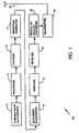
- FIG. 1 is an illustrative block diagram of the variable rate code division multiple access (CDMA) transmission system as described in the Telecommunications Industry Association's Interim Standard TIA/EIA/IS-95-A Mobile Station-Base Station Compatibility Standard for Dual-Mode Wideband Spread Spectrum Cellular System.
- Data for transmission by transmission system 10 is provided by a variable rate data source 12.
- the variable rate data source is a variable rate vocoder used for the variable encoding of speech signals as described in detail in U.S. Patent No. 5,414,796 which is assigned to the assignee of the present invention.
- variable rate transmission system 10 transmits data in frames in accordance with TIA/EIA IS-95-A.
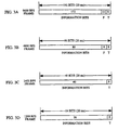
- Variable rate data source 12 receives digitized samples of input speech and encodes the speech to provide packets of encoded speech as illustrated in FIGS. 3A - 3D .
- the output of variable rate data source 12 are the information bits shown in FIGS.3A-3D .
- variable rate data source 12 provides variable rate packets of data for transmission at four possible rates 9600 bps, 4800 bps, 2400 bps and 1200 bps, referred to herein as full, half, quarter, and eighth rates.
- Speech samples encoded at full rate contain 172 information bits
- samples encoded at half rate contain 80 information bits
- samples encoded at quarter rate contain 40 information bits
- samples encoded at eighth rate contain 16 information bits.
- variable rate packets provided to packetizer 13 which in the exemplary embodiment selectively appends cyclic redundancy check (CRC) bits and tail bits.
- CRC cyclic redundancy check
- FIG. 3A when a frame is encoded by the variable rate data source 12 at full rate, packetizer 13 generates and appends 12 CRC bits and 8 tail bits.
- FIG. 3B when a frame is encoded by the variable rate data source 12 at half rate, packetizer 13 generates and appends 8 CRC bits and 8 tail bits.
- FIG. 3C when a frame is encoded by the variable rate data source 12 at quarter rate, packetizer 13 generates and appends 8 tail bits.
- FIG. 3D when a frame is encoded by the variable rate data source 12 at eighth rate, packetizer 13 generates and appends 8 tail bits.
- encoder 14 encodes the bits of the variable rate packets for error detection and correction purposes.
- encoder 14 is a rate 1/3 convolutional encoder.
- the convolutionally encoded symbols are then provided to repetition generator 17.
- repetition generator 17 receives the packets. For packets of less than full rate, repetition generator 17 generates duplicates of the symbols in the packets to provide packets of a constant data rate. When the variable rate packet is half rate, then repetition generator 17 introduces a factor of two redundancy, i.e. each symbol is repeated twice within the output packet. When the variable rate packet is quarter rate, then repetition generator 17 introduces a factor of four redundancy. When the variable rate packet is eighth rate, then repetition generator 17 introduces a factor of eight redundancy.
- the encoded symbols are provided to CDMA spreader 16, an implementation of which is described in detail in U.S. Patent Nos. 5,103,459 and 4,901,307 which are assigned to the assignee of the present invention.
- CDMA spreader 16 maps six encoded symbols to a 64 bit Walsh symbol and then spreads the Walsh symbols in accordance with a pseudorandom noise (PN) code.
- PN pseudorandom noise
- repetition generator 17 provides the redundancy by dividing the data packet into smaller sub-packets referred to as "power control groups".
- each power control group consists of 6 Walsh symbols.
- the constant rate frame is generated by consecutively repeating each power control group the requisite number of times to fill the frame as described above.
- the packets are then provided to a data burst randomizer 18 which removes the redundancy from the packets in accordance with a pseudorandom process as described in U.S. Patent No. 5,535,239 assigned to the assignee of the present invention.
- Data burst randomizer 18 selects one of the power control groups for transmission in accordance with a pseudorandom selection process and gates the other redundant copies of that power control group.
- the output from data burst randomizer 18 consists of sequences of gated values with value 0 bracketing sequences of ungated antipodal data with values of +1 and -1.
- FIG. 4 illustrates a portion of an exemplary transmission signal having a long null portions of value 0 bracketed by an antipodal portions of +1's and -1's.
- Data burst randomizer 18 provides the packet to spreader 16.
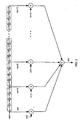
- FIR filter 20 is a 4 times oversampled 48-tap FIR 20 filter illustrated in FIG. 2 . As shown in FIG. 2 , each sample is delayed by one fourth of the period of the input sequence. Thus, there is a four times redundancy in the data stream.
- the filtered signal is then provided to digital to analog converter 22 and converted to an analog signal.
- the analog signal is then provided to transmitter 24 which upconverts and amplifies the signal for transmission through antenna 26.
- FIR filter 20 would be implemented by means of a digital signal processor or specially designed hardware programmed to perform the numerical calculations of equation 1 .
- the power required to operate the processor or specialized hardware may be unacceptably high. So there is a need for a more efficient means of implementing the FIR filter.
- a digital filter of linear phase non-cyclic type comprises a shift register composed of serially connected delay elements with a specified delay time.
- the outputs from the individual delay elements are multiplied and added so that the output sampling frequency is twice that of the input sampling frequency which enters the shift register.
- the number of multiplications is significantly reduced by making the number of output lines from the delay elements to be odd and by placing adders between the shift register and the device for carrying out multiplications.
- An alternative method is to use read only memories instead of the means for carrying out multiplications.
- EP-A-0 492 578 which describes that digital data provided in the form of a serial signal is fetched into an N-bit shift register and parallel N-bit data output therefrom is provided as address data to address input terminals of a memory.
- the memory there are pre-stored at respective addresses defined by the N-bit data the total sum value of multiplied outputs obtained by multiplying the address values and the bit data of a coefficient h(n-i) defining an impulse response characteristic.
- the N-bit data is provided to an address input terminal of the memory to read out therefrom a digital value corresponding to the output voltage of a digital filter.
- the digital value is D/A converted to obtain the output voltage of the digital filter.
- the method for more efficiently implementing FIR filter 20 employs a ROM (read only memory) based look up in which the values of the data in the delay elements are used to select a pre-calculated output value.
- ROM read only memory
- the operation is described in terms of using a read only memory, that other combinatorial logic elements can be used to generate the outputs as described in the exemplary embodiment using read only memory elements.
- the table can be reduced to a table with 3 12 different entries which, although representing a distinct improvement, is still impractical for many applications.
- a first method by which the size of the look up table can be reduced is by implementing the look up table in two parts. Finding the output that results from the twelve values of x(n) to x(n-11) can be achieved by first finding the contribution from x(n) to x(n-5) and then finding the contribution from x(n-6) to x(n-11). FIR filtering is a linear operation. Hence, the output of the filter can be found simply by summing the two contributions.
- the FIR filter is symmetric.
- the filter coefficients for determining contributions for x(n) to x(n-5) may also be used to determine contributions for x(n-6) to x(n-11). This further reduces the necessary number of elements in the look-up table to 3 6 .
- the next method for reducing the size of the look up table is by taking advantage of the fact that there are only a limited number of ways that 0's can occur in the data stream as a result of the operation of the data burst randomizer.
- the data burst randomizer operates to create a signal having sequences of antipodal bits (+1's and 1's) bracketed by sequences of all 0's.
- sequences of antipodal bits +1's and 1's
- a first row of the table represents sixty-four possible combinations of un-gated power control groups, i.e. power control groups consisting only of antipodal +1's and -1's.
- the seventh row of the table represents the single entry required for a fully gated power control group masked to provide all 0's.
- the remaining rows of the table represent the chip patterns associated with streams of chips having gated power control groups being shifted in or shifted out.
- the total number of entries required to implement TABLE I is only 189. This is significantly less than the 3 12 entries that would be required if the look up table did not exploit either FIR filter linearity or the constraints provided by the data burst randomizer.
- a FIR filter apparatus for use in filtering an input signal stream comprised of sequences of antipodal signals bracketed by sequences of null signals.
- the filter apparatus comprises means for storing a look up table containing a FIR filter output value for each of a predetermined set of unique permissible input bit stream patterns and means for successively applying portions of the input digital signal stream to the means for storing the table to output a sequence of output values corresponding to a filtered version of the input stream.
- the predetermined set of permissible input patterns includes only patterns containing either all antipodal signals, all null signals, leading antipodal signals followed by trailing null signals, or leading null signals followed by trailing antipodal signals.
- the apparatus is employed within a digital cellular telephone configured to encode and transmit signals in accordance with CDMA protocols.
- the means for storing the filter response table is a ROM.
- the input to the filter forms the address to the ROM.
- the output of the ROM therefore provides the partial FIR filter response to that input.
- separate in-phase and quadrature phase FIR values are stored.
- the FIR filter is four times over sampled.
- a data value enters the FIR filter it is applied to the first tap.
- the input value then proceeds to be applied four times to the tap values with different phase coefficients.
- Each application of that data value to the first tap of the filter can be referred to as a filter phase.
- the ROM filter table is sub-divided into four separate sub-tables corresponding to each of four possible filter phases.
- the output values of the FIR filter table are predetermined to emulate a forty-eight tap four times oversampled FIR filter.
- the output values are pre-calculated from a set of forty-eight coefficient values with each set of twelve coefficient values employed for generating the output values of the corresponding four phases of the table.
- each of the four sub-tables of each of the in-phase and quadrature phase tables stores 189 entries for a total of 756 entries per table.
- the total number of entries per table is only 378. This further reduction in table size is achieved by taking advantage of the linearity of the filter. In alternate implementation, the table size can be reduced to only 128 entries. A wide range of other embodiments may be provided consistent with the principles of the invention.
- the FIR filter table of the invention will be generally described with reference to FIG. 5 . Then, a specific exemplary implementation of the invention will be described with reference to FIG. 6 .
- FIG. 5 illustrates an FIR filter ROM (read only memory) 100 for use as the filter 20 of the transmission system of FIG. 1 or for use in any other filtering applications consistent with principles of the invention.
- FIR filter ROM 100 stores a single FIR filter output value for each unique permissible input pattern.
- the FIR filter processes signals composed of strings of null values (0's) and strings of antipodal values (+1's and -1's) such that the input strings received by the filter are limited to strings having either all antipodal values (+1's and -1's), all null values (0's), leading null values followed by trailing antipodal values or leading antipodal values followed by trailing null values.
- the number of permissible combinations of input strings is significantly less than would otherwise be required if all possible combinations of antipodal values and null values were permissible.
- ROM 100a stores the information provided in TABLES III and IV.
- TABLES III and IV provide the output information for the first of the four filter phases.
- ROM 100a stores the information necessary for the remaining three phases not provided in TABLES III and IV. The information necessary to complete ROM 100a for the remaining three phases can be computed from the information provided in TABLE II. Likewise, all four phases for ROM 100b can be computed from the information provided in TABLE II.
- the FIR filter of the present invention operates using a system clock which runs at eight times the PN chip rate.
- the permissible streams of +1's and -1's within the table are identified as input addresses or tag values 102 and the corresponding FIR filter output values are identified by reference numerals 104.
- the table may be provided. An implementation having separate sub-tables is discussed below with reference to FIG. 6 .
- a shift register 106 is employed to incrementally shift streams of input samples into FIR filter ROM 100 thereby allowing values corresponding to an input stream to be applied, substantially in parallel, to the address tag values to identify the corresponding output filter value. Since the FIR filter table contains all permissible combinations of input streams, the corresponding filtered output value is therefore contained somewhere within the table and can be read out. By merely reading out pre-calculated output filter values, rather than directly calculating the output values as is commonly employed in conventional FIR filters, significant power consumption savings may be achieved. Moreover, the filter values may be readily modified to provide, for example, differing FIR filter coefficients.
- the FIR filter outputs one output value per stream position, then increments the stream position by one sample point. Hence, output values are generated at the same frequency as sample values of the input signal. Thus, if the input signal is sampled with four samples per chip, then the output signal of the FIR filter likewise has four samples per filtered chip. In general, the input signal can be sampled as often as desired to generate any selected number of output samples per chip. In some implementations, the input signal is "sampled" only twice per chip.
- FIR filter ROM 100 generates four output values for each input stream. This is achieved by subdividing FIR filter ROM 100 into four separate tables corresponding to the four separate phases of the filter. For the purposes of providing a clear overview of the operation of the invention, the FIR filter ROM 100 of FIG. 5 is illustrated merely as a single phase filter providing only one output value per stream of input sample values shifted into FIR filter ROM 100 by shift register 106.
- the sequence of chips of sample stream is applied to the various sequences of bits of the address values until a match is achieved, at which time the corresponding filter output value is read out for subsequent processing.
- one value is output corresponding to the entire stream of input values.
- the stream of input values are defined by a sliding window, which is incrementally translated with respect to the input signal to allow a sequence of incrementally different streams to be applied to the table to yield a sequence of corresponding incrementally different filtered output values.
- the window initially selects samples N through N + 11 to generate a first filter output value, the window is then repositioned to select samples N + 1 through N + 12 to generate a second output value, and so on.
- an entire input signal is incrementally filtered to generate a sequence of output values with one output value per window location.
- sample values of zero, or some other default value may be padded onto the actual sample values to provide a complete stream.
- the output values are represented digitally, to any desired degree of precision, by employing a multiple bit representation.
- the output values may be represented using eight bits, eleven bits, etc.
- the precision to which the output values need to be represented may be constrained, in part, by the characteristics of the input signal and by the number of samples per stream.
- an eleven-bit representation of the output filter values is employed.
- FIR filter of FIG. 6 provides separate in-phase 402 and quadrature phase 404 filtering components. Each component generates four output values for each stream of twelve input chips. As such, both components represent four-phase filters.
- Two separate FIR filter ROM tables 100a and 100b are illustrated. Each contains four sub-tables (not separately shown) corresponding to each of the four phases. Output values stored within the tables are generated to emulate a forty-eight coefficient filter wherein twelve of the coefficients are employed in connection with each phase.
- the first six chips of the input stream are applied to FIR filter ROM tables 100a and 100b to generate four output values, with one output value per phase of a four-phased clock period.
- the in-phase (I) filter ROM 100a and the quadrature phase (Q) filter ROM 100b are implemented slightly differently.
- the 1-filter is a forty-eight tap filter with even symmetry such that the peak of the resulting impulse response falls between h(23) and h(24) for coefficients h(0) to h(47). Moreover, h(23) is equal to h(24).
- the Q-filter is a forty-seven tap filter with odd symmetry such that the peak of the impulse response falls on h(23) for a filter having coefficients h(0) through h(46).
- the Q-filter has only forty-seven coefficient values, rather than forty-eight values and cannot be evenly divided by four as with the 1-filter.
- the phase 0 output is the sum of eleven coefficients, whereas the other three phase outputs are each the sum of twelve coefficients.
- the ROM values of the Q-filter are stored to weight center tap contribution h(23) by half.
- Q-filter ROM 100b is read using input chips 6:1 as the address for the first access, and chips 6:11 on the second access, rather than using input chips 5:0 on the first access and 6:11 on the second access. In effect, this counts the half-weighted center tap coefficients twice to thereby apply the center coefficient at its full weight.
- the odd symmetry of Q-filter ROM 100b requires a simple page mapping to track an additional detail: the first half of the phase one coefficients are symmetric with respect to the second half of the phase three coefficients and vice versa.
- Table III Sixty-four entries for in-phase ROM 100a are set forth in Table III. In the exemplary embodiment, only half of the entries in Table III provided below are stored in ROM 100, because the output value for "negative" inputs can be derived by negating the output values from the corresponding "positive” inputs.
- the sixty-four entries correspond to the un-gated input chip streams i.e. chip streams having antipodal values only. Within the table, the antipodal values of the ungated signal are represented as +'s and - 's.
- Table IV provides the entries for the partially gated and completely gated chip streams.
- shifted-in gated values are provided in the left two columns.
- Shifted-out gated values are provided in the right two columns.
- "0's" represent the gated or null values.
- the gated values are either leading values or trailing values, depending upon whether the gated values are being shifted into or out of the FIR filter.
- the final entry in the Table, having all "0's" represents the fully gated chip stream. Referring back to Table I, there are a total of 189 possible combinations that can occupy the first six or second six taps of the filter. To provide for the four possible phases of the filter would require 756 possible combinations.
- the output values represented in Table IB and IV are derived from the coefficient values of Table II.
- an input chip stream having the first six chips represented by +1, -1, +1, -1, +1, -1, or "+ - + - + -”.
- this corresponds to h(0) - h(4) + h(8) - h(12) + h(16) - h(20) or (-12) - (+10) + (17) - (+4) + (-6) - (+44) or -59 which is the value within Table III corresponding to the "+ - + - + -" input address combination.
- the output for the complement input "- + - + - +" is +59.
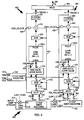
- FIG. 6 illustrates a FIR filter unit 400 having a in-phase portion 402 and a quadrature phase portion 404. Outputs of the two portions are combined onto a single output signal path 406 by a multiplexer 408 for subsequent conversion to analog signals for transmission.
- Power control groups composed entirely of +1's and -1's are received along an input line 410.
- a DBR gating value of G or NG is input along a DBR line 412.
- One DBR gating value is received for each chip of the input power control group. If the gating value is G, then the power control group is gated and the corresponding chip may be regarded as being a 0 value. If the DBR gating value is NG, then the chip value is ungated and retains its input value of +1 or -1.
- the stream of input chips received along line 410 is first combined with I-PN and U-PN signals to perform spreading, then the resulting spread signals are shifted in using a shift register 428.
- the shift register 412 outputs twelve bits in parallel along separate lines 414 and 416.
- Line 414 contains bits 5:0, whereas line 416 carries bits 6:11.
- a multiplexer 418 selects either the lower six bits or the upper six bits depending upon the value of an odd clock signal received along line 420. If the clock is odd, then the lower bits are selected, if the clock is even, then the upper bits are selected.
- the MSB of the selected bits is separated onto a line 422 for use in controlling a pair of XOR gates 424 and 426.
- the lower five LSB's are routed directly into XOR gate 424. If the MSB is 0, then the other five bits are inverted to yield complement thereof to exploit the linearity feature summarize above.
- the resulting five bits are routed into a DBR gate address mask unit 426 which also receives the G or NG bits from a twelve-tap DBR shift register 428 connected to input line 412.
- the DBR gate address mask matches the G and NG signals from shift register 428 with the corresponding bits of the input chip signal received from gate 424.
- the DBR gate address mask also receives a filter phase signal along an input line 432 for selecting the appropriate phase.
- I-FIR ROM 100a is composed of four separate table portions corresponding to the four separate phases.
- the DBR gate address mask then maps the +1's and -1's of the chip signal for each phase, with the corresponding G and NG values of the DBR signal to yield an address suitable for selecting the correct corresponding filter value from an 1-FIR ROM 100a .
- the actual format of the address depends upon how the data is stored within the ROM. Suitable addresses are described above with reference to Table IV.
- the address generated by the DBR gate address mask uniquely identifies one entry within ROM 100.
- ROM 100 contains 378 entries. To uniquely address each entry, a total of nine address bits are employed. The nine bit address is generated from the six ternary values input into the filter.
- the nine bit address is applied to the ROM table 100a to generate a single unique output value represented digitally using eleven bits.
- the eleven bits of the output value are fed into the second XOR gate 426 for inversion if the original MSB was 0.
- the resulting value is stored at latch 428 for subsequent combination with the output value corresponding to the upper six bits of the input chip stream.
- the upper six bits are processed, in much the same manner as the lower six bits, to yield a second output value.
- the first output value stored in latch 428 is combined with a second output value by an adder gate 434 to yield a digital signal for outputting.
- the two least significant bits of the digital signal are truncated, then the signal is fed into multiplexer 408 for subsequent output onto line 406 along with output values from the quadrature phase portion of the filter.
- each odd clock within a chip four values are output from I-ROM 100a corresponding to the four filter phases.
- the four output values are each stored within latch 432.
- four additional values are output from 1-ROM 100a corresponding to the four phases.
- the first sets of values generated during the odd clock are based upon the lower six bits of the input chip stream.
- the second four values generated during the even clock are based upon the upper six bits of the input chip stream.
- the pairs of first and second values are summed to yield a total of four output values per pair of clock signals.
- the quadrature phase portion includes a shift register 462 which outputs bits in parallel along three separate lines 464, 465 and 466 to a multiplexer 468.
- multiplexer 468 receives three different inputs corresponding to the 5:0, 6:1 and 6:11 bits. This is provided to accommodate for the slight asymmetry in the quadrature phase filter coefficients summarized above.
- Multiplexer 468 selects signals from one of the three input lines based both upon the odd clock signal 420 and the filter phase signal 432. For the first filter phase, during the odd clock, bits 6:1 are selected and bits 6:11 are selected during the even clock. For the other three phases, selection is between the 5:0 and 6:11 bits as described with reference to the in-phase portion.
- the six bits selected by the multiplexer are routed to an XOR gate 474 and the MSB are routed along a line 472.
- the XOR gate inverts the bits, depending upon the MSB, and routes the resulting bits into a DBR gate address mask 475 which operates in the same manner as that of mask 426 of the in-phase portion.
- a nine bit address is applied to a Q-FIR ROM 100b, outputs of which are routed through a second XOR gate 476 into a latch 482.
- the values latched during the odd clock are combined with values output from the ROM 100b during the even clock to yield final output signals for transmission onto output line 406 via multiplexer 408.
- Output values for the DBR-gated input values are computed from the output values corresponding to the ungated input values by summing two successive accesses to ROM tables 100a and 100b.
- the first access uses the ungated or "unmasked" filter input as an address
- the second access uses the input with DBR-gated chips inverted as compared to those of the first access. Summing the resulting two output values together therefore has the net effect of canceling the DBR-gated chip inputs.
- the summed output value is shifted by a bit position to reduce the value by half to cancel a times-two scaling inherently occurring as a result of the summation of the two output values.
- ROM 100 itself is somewhat more complex than the ROM of the preceding embodiment.
- ROM 100 of the alternative embodiment stores only 128 unmasked values, arranged as 64 words twice as wide as the words of FIG. 6 making it approximately one-third the size of ROM 100 which includes DBR gated values.
Landscapes
- Physics & Mathematics (AREA)
- Engineering & Computer Science (AREA)
- Computer Hardware Design (AREA)
- Mathematical Physics (AREA)
- Digital Transmission Methods That Use Modulated Carrier Waves (AREA)
- Mobile Radio Communication Systems (AREA)
- Telephone Function (AREA)
- Cable Transmission Systems, Equalization Of Radio And Reduction Of Echo (AREA)
- Compression, Expansion, Code Conversion, And Decoders (AREA)
Applications Claiming Priority (3)
| Application Number | Priority Date | Filing Date | Title |
|---|---|---|---|
| US672205 | 1996-06-27 | ||
| US08/672,205 US5870431A (en) | 1996-06-27 | 1996-06-27 | ROM-based finite impulse response filter for use in mobile telephone |
| PCT/US1997/010925 WO1997050174A1 (en) | 1996-06-27 | 1997-06-23 | Rom-based finite impulse response filter for use in mobile telephone |
Publications (2)
| Publication Number | Publication Date |
|---|---|
| EP0908009A1 EP0908009A1 (en) | 1999-04-14 |
| EP0908009B1 true EP0908009B1 (en) | 2010-07-14 |
Family
ID=24697582
Family Applications (1)
| Application Number | Title | Priority Date | Filing Date |
|---|---|---|---|
| EP97931357A Expired - Lifetime EP0908009B1 (en) | 1996-06-27 | 1997-06-23 | Rom-based finite impulse response filter for use in mobile telephone |
Country Status (15)
| Country | Link |
|---|---|
| US (1) | US5870431A (ru) |
| EP (1) | EP0908009B1 (ru) |
| JP (2) | JP2000514259A (ru) |
| CN (1) | CN1115777C (ru) |
| AT (1) | ATE474376T1 (ru) |
| AU (1) | AU717714B2 (ru) |
| BR (1) | BR9711599A (ru) |
| CA (1) | CA2254929C (ru) |
| DE (1) | DE69739935D1 (ru) |
| HK (1) | HK1020503A1 (ru) |
| MY (1) | MY117766A (ru) |
| RU (1) | RU2189109C2 (ru) |
| TW (1) | TW338858B (ru) |
| WO (1) | WO1997050174A1 (ru) |
| ZA (1) | ZA975595B (ru) |
Families Citing this family (32)
| Publication number | Priority date | Publication date | Assignee | Title |
|---|---|---|---|---|
| US6678311B2 (en) | 1996-05-28 | 2004-01-13 | Qualcomm Incorporated | High data CDMA wireless communication system using variable sized channel codes |
| TW369648B (en) * | 1996-09-02 | 1999-09-11 | Koninkl Philips Electronics Nv | Device for write compensation in magnetic media recording |
| US6628722B1 (en) | 1998-06-19 | 2003-09-30 | Lucent Technologies Inc. | Decoding technique in discrete multi-tone (DMT) based communications systems |
| CN1076917C (zh) * | 1998-09-11 | 2001-12-26 | 华为技术有限公司 | 码分多址扩频无线通信系统基站的基带成形滤波器 |
| US6570907B1 (en) | 1999-10-04 | 2003-05-27 | Ericsson Inc. | Simplified finite impulse response (FIR) digital filter for direct sequencespread spectrum communication |
| US6731706B1 (en) * | 1999-10-29 | 2004-05-04 | Intel Corporation | Square root raised cosine symmetric filter for mobile telecommunications |
| KR100378592B1 (ko) | 2000-07-31 | 2003-03-31 | 한국전자통신연구원 | 디지털 이동 통신용 108 탭 1대4 인터폴레이션유한임펄스응답 필터장치 |
| US7068780B1 (en) * | 2000-08-30 | 2006-06-27 | Conexant, Inc. | Hybrid echo canceller |
| SE520067C2 (sv) * | 2000-09-04 | 2003-05-20 | Hans Haellstroem | Anordning och förfarande för att uppskatta parametrar i en signal |
| US6820103B2 (en) | 2000-11-03 | 2004-11-16 | Qualcomm Inc. | Digital filter with state storage |
| EP1239640B1 (en) * | 2000-12-20 | 2004-05-06 | Motorola, Inc. | Quadrature modulator with programmable pulse shaping |
| KR100425418B1 (ko) * | 2001-09-07 | 2004-03-30 | 삼성탈레스 주식회사 | 룩업 테이블을 이용한 블록 보간 필터 구조 |
| US6768684B2 (en) * | 2002-01-25 | 2004-07-27 | Sun Microsystems, Inc. | System and method for small read only data |
| US7986932B1 (en) * | 2002-11-19 | 2011-07-26 | National Semiconductor Corporation | Fixed point FIR filter with adaptive truncation and clipping and wireless mobile station using same |
| US20050201457A1 (en) * | 2004-03-10 | 2005-09-15 | Allred Daniel J. | Distributed arithmetic adaptive filter and method |
| DE102004042368B4 (de) * | 2004-09-01 | 2009-12-17 | Infineon Technologies Ag | Digitales Filter zur sendeseitigen Pulsformung |
| DE102005046245A1 (de) * | 2005-09-28 | 2007-04-05 | Atmel Germany Gmbh | Vorrichtung zum Überführen eines komplexwertigen Bandpaßsignals in ein digitales Basisbandsignal |
| US8920343B2 (en) | 2006-03-23 | 2014-12-30 | Michael Edward Sabatino | Apparatus for acquiring and processing of physiological auditory signals |
| RU2631976C2 (ru) * | 2016-03-15 | 2017-09-29 | Федеральное государственное бюджетное образовательное учреждение высшего образования Московский авиационный институт (национальный исследовательский университет) (МАИ) | Перестраиваемый цифровой фильтр с программируемой структурой |
| US10659112B1 (en) | 2018-11-05 | 2020-05-19 | XCOM Labs, Inc. | User equipment assisted multiple-input multiple-output downlink configuration |
| US10812216B2 (en) | 2018-11-05 | 2020-10-20 | XCOM Labs, Inc. | Cooperative multiple-input multiple-output downlink scheduling |
| US10756860B2 (en) | 2018-11-05 | 2020-08-25 | XCOM Labs, Inc. | Distributed multiple-input multiple-output downlink configuration |
| US10432272B1 (en) | 2018-11-05 | 2019-10-01 | XCOM Labs, Inc. | Variable multiple-input multiple-output downlink user equipment |
| KR20210087089A (ko) | 2018-11-27 | 2021-07-09 | 엑스콤 랩스 인코퍼레이티드 | 넌-코히어런트 협력 다중 입출력 통신 |
| US10756795B2 (en) | 2018-12-18 | 2020-08-25 | XCOM Labs, Inc. | User equipment with cellular link and peer-to-peer link |
| US11063645B2 (en) | 2018-12-18 | 2021-07-13 | XCOM Labs, Inc. | Methods of wirelessly communicating with a group of devices |
| US11330649B2 (en) | 2019-01-25 | 2022-05-10 | XCOM Labs, Inc. | Methods and systems of multi-link peer-to-peer communications |
| US10756767B1 (en) | 2019-02-05 | 2020-08-25 | XCOM Labs, Inc. | User equipment for wirelessly communicating cellular signal with another user equipment |
| US10735057B1 (en) | 2019-04-29 | 2020-08-04 | XCOM Labs, Inc. | Uplink user equipment selection |
| US10686502B1 (en) | 2019-04-29 | 2020-06-16 | XCOM Labs, Inc. | Downlink user equipment selection |
| US11411778B2 (en) | 2019-07-12 | 2022-08-09 | XCOM Labs, Inc. | Time-division duplex multiple input multiple output calibration |
| US11411779B2 (en) | 2020-03-31 | 2022-08-09 | XCOM Labs, Inc. | Reference signal channel estimation |
Citations (1)
| Publication number | Priority date | Publication date | Assignee | Title |
|---|---|---|---|---|
| EP0492578A2 (en) * | 1990-12-28 | 1992-07-01 | Advantest Corporation | Digital filter |
Family Cites Families (7)
| Publication number | Priority date | Publication date | Assignee | Title |
|---|---|---|---|---|
| US4551816A (en) * | 1970-12-28 | 1985-11-05 | Hyatt Gilbert P | Filter display system |
| US4817025A (en) * | 1984-02-03 | 1989-03-28 | Sharp Kabushiki Kaisha | Digital filter |
| US5369606A (en) * | 1992-09-14 | 1994-11-29 | Harris Corporation | Reduced state fir filter |
| NZ259776A (en) * | 1992-11-16 | 1997-06-24 | Ceridian Corp | Identifying recorded or broadcast audio signals by mixing with encoded signal derived from code signal modulated by narrower bandwidth identification signal |
| US5535150A (en) * | 1993-04-20 | 1996-07-09 | Massachusetts Institute Of Technology | Single chip adaptive filter utilizing updatable weighting techniques |
| US5586068A (en) * | 1993-12-08 | 1996-12-17 | Terayon Corporation | Adaptive electronic filter |
| US5566101A (en) * | 1995-08-15 | 1996-10-15 | Sigmatel, Inc. | Method and apparatus for a finite impulse response filter processor |
-
1996
- 1996-06-27 US US08/672,205 patent/US5870431A/en not_active Expired - Lifetime
-
1997
- 1997-06-20 MY MYPI97002780A patent/MY117766A/en unknown
- 1997-06-23 CA CA002254929A patent/CA2254929C/en not_active Expired - Fee Related
- 1997-06-23 EP EP97931357A patent/EP0908009B1/en not_active Expired - Lifetime
- 1997-06-23 AU AU35003/97A patent/AU717714B2/en not_active Ceased
- 1997-06-23 BR BR9711599A patent/BR9711599A/pt not_active Application Discontinuation
- 1997-06-23 JP JP10503464A patent/JP2000514259A/ja not_active Withdrawn
- 1997-06-23 AT AT97931357T patent/ATE474376T1/de not_active IP Right Cessation
- 1997-06-23 RU RU99101863/09A patent/RU2189109C2/ru not_active IP Right Cessation
- 1997-06-23 DE DE69739935T patent/DE69739935D1/de not_active Expired - Lifetime
- 1997-06-23 CN CN97194884A patent/CN1115777C/zh not_active Expired - Lifetime
- 1997-06-23 WO PCT/US1997/010925 patent/WO1997050174A1/en active IP Right Grant
- 1997-06-24 ZA ZA975595A patent/ZA975595B/xx unknown
- 1997-06-26 TW TW086108972A patent/TW338858B/zh not_active IP Right Cessation
-
1999
- 1999-10-07 HK HK99104414.2A patent/HK1020503A1/xx unknown
-
2011
- 2011-06-14 JP JP2011132557A patent/JP5118234B2/ja not_active Expired - Lifetime
Patent Citations (1)
| Publication number | Priority date | Publication date | Assignee | Title |
|---|---|---|---|---|
| EP0492578A2 (en) * | 1990-12-28 | 1992-07-01 | Advantest Corporation | Digital filter |
Non-Patent Citations (1)
| Title |
|---|
| SODERSTRAND M.A.; TRUJILLO T.C.; CHOI H.: "Flash-Memory Based Digital Filter and Baseband Modulator for FQPSK Transmitter", PROCEEDINGS OF THE 38TH MIDWEST SYMPOSIUM ON CIRCUITS AND SYSTEMS, RIO DE JANEIRO, BRAZIL, 13-16 AUG. 1995, vol. 1, 13 August 1995 (1995-08-13), NEW YORK, NY, USA, pages 358 - 361, XP010165142 * |
Also Published As
| Publication number | Publication date |
|---|---|
| CN1220058A (zh) | 1999-06-16 |
| ZA975595B (en) | 1998-10-08 |
| CN1115777C (zh) | 2003-07-23 |
| CA2254929A1 (en) | 1997-12-31 |
| ATE474376T1 (de) | 2010-07-15 |
| MY117766A (en) | 2004-08-30 |
| JP2011259437A (ja) | 2011-12-22 |
| AU717714B2 (en) | 2000-03-30 |
| JP2000514259A (ja) | 2000-10-24 |
| CA2254929C (en) | 2005-06-14 |
| HK1020503A1 (en) | 2000-05-05 |
| BR9711599A (pt) | 1999-08-24 |
| US5870431A (en) | 1999-02-09 |
| RU2189109C2 (ru) | 2002-09-10 |
| AU3500397A (en) | 1998-01-14 |
| JP5118234B2 (ja) | 2013-01-16 |
| TW338858B (en) | 1998-08-21 |
| EP0908009A1 (en) | 1999-04-14 |
| WO1997050174A1 (en) | 1997-12-31 |
| DE69739935D1 (de) | 2010-08-26 |
Similar Documents
| Publication | Publication Date | Title |
|---|---|---|
| EP0908009B1 (en) | Rom-based finite impulse response filter for use in mobile telephone | |
| JP3214867B2 (ja) | π/4DQPSK変調方法 | |
| JP3550598B2 (ja) | Cdmaモデム用の効率的な多チャンネル濾波 | |
| JP2591864B2 (ja) | ディジタルフィルタ | |
| WO1999017221A1 (en) | Method for efficiently computing sequence correlations | |
| GB2185367A (en) | Method for decoding error correcting block codes | |
| US5592517A (en) | Cascaded comb integrator interpolating filters | |
| US4518947A (en) | Apparatus for decoding redundant interleaved data | |
| EP0886915B1 (en) | Floating point digital transversal filter | |
| EP0975091B1 (en) | Digital filter | |
| EP0492578B1 (en) | Digital filter | |
| JPH03235553A (ja) | π/4シフトQPSK変調器及びそれを用いた通信装置 | |
| EP1033816B1 (en) | D/A conversion apparatus | |
| CA2216128C (en) | Efficient digital filter and method using coefficient precombining | |
| KR100473220B1 (ko) | 이동전화에서사용하기위한rom기반의유한임펄스응답필터 | |
| US7072422B2 (en) | Device and method for spectrally shaping a transmission signal in a radio transmitter | |
| US6678320B1 (en) | Efficient finite impulse response filter implementation for CDMA waveform generation | |
| US7065145B2 (en) | Digital carrierless amplitude and phase modulation (CAP) transmitter using vector arithmetic structure (VAS) | |
| KR100746856B1 (ko) | 무승산기 fir 디지털 필터 및 그 설계 방법 | |
| Anderson et al. | Architecture and construction of a hardware sequential encoder for speech | |
| KR100425644B1 (ko) | 계산량을 감축시키기 위한 필터링 방법과 그 방법들을이용한 가우시안 필터 및 그 필터를 갖는 변조기 | |
| GB2368244A (en) | Signal processor with look-up table for modulating data | |
| JPH11330913A (ja) | デジタルフィルタ | |
| Sebesta et al. | Fast GMSK modulation in DSP | |
| JPH0716145B2 (ja) | ディジタルトランスバーサルフィルタ |
Legal Events
| Date | Code | Title | Description |
|---|---|---|---|
| PUAI | Public reference made under article 153(3) epc to a published international application that has entered the european phase |
Free format text: ORIGINAL CODE: 0009012 |
|
| 17P | Request for examination filed |
Effective date: 19981126 |
|
| AK | Designated contracting states |
Kind code of ref document: A1 Designated state(s): AT BE CH DE DK ES FI FR GB GR IE IT LI LU MC NL PT SE |
|
| RAP1 | Party data changed (applicant data changed or rights of an application transferred) |
Owner name: QUALCOMM INCORPORATED |
|
| 17Q | First examination report despatched |
Effective date: 20070824 |
|
| GRAP | Despatch of communication of intention to grant a patent |
Free format text: ORIGINAL CODE: EPIDOSNIGR1 |
|
| GRAS | Grant fee paid |
Free format text: ORIGINAL CODE: EPIDOSNIGR3 |
|
| GRAA | (expected) grant |
Free format text: ORIGINAL CODE: 0009210 |
|
| AK | Designated contracting states |
Kind code of ref document: B1 Designated state(s): AT BE CH DE DK ES FI FR GB GR IE IT LI LU MC NL PT SE |
|
| REG | Reference to a national code |
Ref country code: GB Ref legal event code: FG4D |
|
| REG | Reference to a national code |
Ref country code: CH Ref legal event code: EP |
|
| REG | Reference to a national code |
Ref country code: IE Ref legal event code: FG4D |
|
| REF | Corresponds to: |
Ref document number: 69739935 Country of ref document: DE Date of ref document: 20100826 Kind code of ref document: P |
|
| REG | Reference to a national code |
Ref country code: NL Ref legal event code: VDEP Effective date: 20100714 |
|
| REG | Reference to a national code |
Ref country code: HK Ref legal event code: GR Ref document number: 1020503 Country of ref document: HK |
|
| PG25 | Lapsed in a contracting state [announced via postgrant information from national office to epo] |
Ref country code: NL Free format text: LAPSE BECAUSE OF FAILURE TO SUBMIT A TRANSLATION OF THE DESCRIPTION OR TO PAY THE FEE WITHIN THE PRESCRIBED TIME-LIMIT Effective date: 20100714 Ref country code: FI Free format text: LAPSE BECAUSE OF FAILURE TO SUBMIT A TRANSLATION OF THE DESCRIPTION OR TO PAY THE FEE WITHIN THE PRESCRIBED TIME-LIMIT Effective date: 20100714 Ref country code: AT Free format text: LAPSE BECAUSE OF FAILURE TO SUBMIT A TRANSLATION OF THE DESCRIPTION OR TO PAY THE FEE WITHIN THE PRESCRIBED TIME-LIMIT Effective date: 20100714 |
|
| PG25 | Lapsed in a contracting state [announced via postgrant information from national office to epo] |
Ref country code: PT Free format text: LAPSE BECAUSE OF FAILURE TO SUBMIT A TRANSLATION OF THE DESCRIPTION OR TO PAY THE FEE WITHIN THE PRESCRIBED TIME-LIMIT Effective date: 20101115 |
|
| PG25 | Lapsed in a contracting state [announced via postgrant information from national office to epo] |
Ref country code: BE Free format text: LAPSE BECAUSE OF FAILURE TO SUBMIT A TRANSLATION OF THE DESCRIPTION OR TO PAY THE FEE WITHIN THE PRESCRIBED TIME-LIMIT Effective date: 20100714 Ref country code: SE Free format text: LAPSE BECAUSE OF FAILURE TO SUBMIT A TRANSLATION OF THE DESCRIPTION OR TO PAY THE FEE WITHIN THE PRESCRIBED TIME-LIMIT Effective date: 20100714 Ref country code: GR Free format text: LAPSE BECAUSE OF FAILURE TO SUBMIT A TRANSLATION OF THE DESCRIPTION OR TO PAY THE FEE WITHIN THE PRESCRIBED TIME-LIMIT Effective date: 20101015 |
|
| PG25 | Lapsed in a contracting state [announced via postgrant information from national office to epo] |
Ref country code: DK Free format text: LAPSE BECAUSE OF FAILURE TO SUBMIT A TRANSLATION OF THE DESCRIPTION OR TO PAY THE FEE WITHIN THE PRESCRIBED TIME-LIMIT Effective date: 20100714 |
|
| PLBE | No opposition filed within time limit |
Free format text: ORIGINAL CODE: 0009261 |
|
| STAA | Information on the status of an ep patent application or granted ep patent |
Free format text: STATUS: NO OPPOSITION FILED WITHIN TIME LIMIT |
|
| PG25 | Lapsed in a contracting state [announced via postgrant information from national office to epo] |
Ref country code: IT Free format text: LAPSE BECAUSE OF FAILURE TO SUBMIT A TRANSLATION OF THE DESCRIPTION OR TO PAY THE FEE WITHIN THE PRESCRIBED TIME-LIMIT Effective date: 20100714 |
|
| 26N | No opposition filed |
Effective date: 20110415 |
|
| PG25 | Lapsed in a contracting state [announced via postgrant information from national office to epo] |
Ref country code: ES Free format text: LAPSE BECAUSE OF FAILURE TO SUBMIT A TRANSLATION OF THE DESCRIPTION OR TO PAY THE FEE WITHIN THE PRESCRIBED TIME-LIMIT Effective date: 20101025 |
|
| REG | Reference to a national code |
Ref country code: DE Ref legal event code: R097 Ref document number: 69739935 Country of ref document: DE Effective date: 20110415 |
|
| REG | Reference to a national code |
Ref country code: CH Ref legal event code: PL |
|
| REG | Reference to a national code |
Ref country code: FR Ref legal event code: ST Effective date: 20120229 |
|
| REG | Reference to a national code |
Ref country code: IE Ref legal event code: MM4A |
|
| PG25 | Lapsed in a contracting state [announced via postgrant information from national office to epo] |
Ref country code: LI Free format text: LAPSE BECAUSE OF NON-PAYMENT OF DUE FEES Effective date: 20110630 Ref country code: CH Free format text: LAPSE BECAUSE OF NON-PAYMENT OF DUE FEES Effective date: 20110630 Ref country code: IE Free format text: LAPSE BECAUSE OF NON-PAYMENT OF DUE FEES Effective date: 20110623 Ref country code: FR Free format text: LAPSE BECAUSE OF NON-PAYMENT OF DUE FEES Effective date: 20110630 |
|
| PG25 | Lapsed in a contracting state [announced via postgrant information from national office to epo] |
Ref country code: MC Free format text: LAPSE BECAUSE OF NON-PAYMENT OF DUE FEES Effective date: 20110630 |
|
| PG25 | Lapsed in a contracting state [announced via postgrant information from national office to epo] |
Ref country code: LU Free format text: LAPSE BECAUSE OF NON-PAYMENT OF DUE FEES Effective date: 20110623 |
|
| PGFP | Annual fee paid to national office [announced via postgrant information from national office to epo] |
Ref country code: GB Payment date: 20150526 Year of fee payment: 19 |
|
| PGFP | Annual fee paid to national office [announced via postgrant information from national office to epo] |
Ref country code: DE Payment date: 20150630 Year of fee payment: 19 |
|
| REG | Reference to a national code |
Ref country code: DE Ref legal event code: R119 Ref document number: 69739935 Country of ref document: DE |
|
| GBPC | Gb: european patent ceased through non-payment of renewal fee |
Effective date: 20160623 |
|
| PG25 | Lapsed in a contracting state [announced via postgrant information from national office to epo] |
Ref country code: DE Free format text: LAPSE BECAUSE OF NON-PAYMENT OF DUE FEES Effective date: 20170103 |
|
| PG25 | Lapsed in a contracting state [announced via postgrant information from national office to epo] |
Ref country code: GB Free format text: LAPSE BECAUSE OF NON-PAYMENT OF DUE FEES Effective date: 20160623 |