EP0907790B1 - Equipment for combining a dilution flow with the stock flow passed out of the inlet header in a paper/board machine - Google Patents
Equipment for combining a dilution flow with the stock flow passed out of the inlet header in a paper/board machine Download PDFInfo
- Publication number
- EP0907790B1 EP0907790B1 EP97927205A EP97927205A EP0907790B1 EP 0907790 B1 EP0907790 B1 EP 0907790B1 EP 97927205 A EP97927205 A EP 97927205A EP 97927205 A EP97927205 A EP 97927205A EP 0907790 B1 EP0907790 B1 EP 0907790B1
- Authority
- EP
- European Patent Office
- Prior art keywords
- flow
- pipes
- headbox
- dilution
- plate
- Prior art date
- Legal status (The legal status is an assumption and is not a legal conclusion. Google has not performed a legal analysis and makes no representation as to the accuracy of the status listed.)
- Expired - Lifetime
Links
- 238000010790 dilution Methods 0.000 title claims abstract description 77
- 239000012895 dilution Substances 0.000 title claims abstract description 77
- 238000003754 machining Methods 0.000 claims description 9
- 238000003801 milling Methods 0.000 claims description 9
- 238000000034 method Methods 0.000 abstract description 2
- 239000007788 liquid Substances 0.000 description 27
- 238000010276 construction Methods 0.000 description 25
- 230000001105 regulatory effect Effects 0.000 description 8
- 230000033228 biological regulation Effects 0.000 description 5
- 238000005553 drilling Methods 0.000 description 5
- XLYOFNOQVPJJNP-UHFFFAOYSA-N water Substances O XLYOFNOQVPJJNP-UHFFFAOYSA-N 0.000 description 5
- 238000004140 cleaning Methods 0.000 description 2
- 230000000694 effects Effects 0.000 description 2
- 239000002184 metal Substances 0.000 description 2
- 238000005406 washing Methods 0.000 description 2
- 230000008602 contraction Effects 0.000 description 1
- 239000012530 fluid Substances 0.000 description 1
- 230000014759 maintenance of location Effects 0.000 description 1
- 230000007246 mechanism Effects 0.000 description 1
- 230000008844 regulatory mechanism Effects 0.000 description 1
- 239000000243 solution Substances 0.000 description 1
Images


Classifications
-
- D—TEXTILES; PAPER
- D21—PAPER-MAKING; PRODUCTION OF CELLULOSE
- D21F—PAPER-MAKING MACHINES; METHODS OF PRODUCING PAPER THEREON
- D21F1/00—Wet end of machines for making continuous webs of paper
- D21F1/02—Head boxes of Fourdrinier machines
- D21F1/022—Means for injecting material into flow within the headbox
-
- D—TEXTILES; PAPER
- D21—PAPER-MAKING; PRODUCTION OF CELLULOSE
- D21F—PAPER-MAKING MACHINES; METHODS OF PRODUCING PAPER THEREON
- D21F1/00—Wet end of machines for making continuous webs of paper
- D21F1/02—Head boxes of Fourdrinier machines
-
- D—TEXTILES; PAPER
- D21—PAPER-MAKING; PRODUCTION OF CELLULOSE
- D21F—PAPER-MAKING MACHINES; METHODS OF PRODUCING PAPER THEREON
- D21F1/00—Wet end of machines for making continuous webs of paper
- D21F1/02—Head boxes of Fourdrinier machines
- D21F1/026—Details of the turbulence section
-
- D—TEXTILES; PAPER
- D21—PAPER-MAKING; PRODUCTION OF CELLULOSE
- D21F—PAPER-MAKING MACHINES; METHODS OF PRODUCING PAPER THEREON
- D21F1/00—Wet end of machines for making continuous webs of paper
- D21F1/08—Regulating consistency
Definitions
- the invention concerns a headbox according to the preamble of claim 1.
- a what is called dilution headbox is known, which is understood as a headbox construction in which the basis weight of the web can be regulated across the web width by through valves passing a dilution flow to different locations of width of the headbox and by regulating the quantity of said flow.
- the dilution flow is mixed with the stock flow passed out of the inlet header of the headbox.
- the dilution flow can consist of pure or fibrous liquid.
- the dilution water can be, for example, wire water taken as retention from the web.
- the headbox comprises an equipment for combining a dilution flow with the stock flow derived from the inlet header of the paper/board machine, by means of which the dilution liquid, preferably dilution water, is passed into connection with the stock flow passed from the inlet header preferably in connection with the tube manifold placed after the inlet header.
- the basis weight of the web can be regulated across the wire width by through regulation valves V 1 , V 2 ... passing the desired dilution flow to different locations across the width of the headbox.
- the dilution flow is passed into each row of pipes in the tube manifold and in each row of pipes into all the pipes placed one above the other in the row of pipes.
- the dilution flow duct consists of a resilient pipe passed from the valve, which pipe is preferably connected with the tube manifold and out of which pipe the flow is distributed through a duct portion with inclined walls uniformly into each pipe in the rows of pipes in the tube manifold.
- the flow can be distributed evenly into all the pipes in the row of pipes in the tube manifold, also into the first pipe in the direction of flow L 1 of the dilution liquid.
- a poorly distributed dilution flow increases the instability/residual scattering of the basis weight of the paper/board.
- the narrowing duct portion for the dilution flow has been formed into a middle plate component so that one wall of the narrowing duct portion consists of a plate which is placed as the first plate in the flow direction L 2 of the stock flow and which contains the flow ducts for the stock flow.
- a separate throttle plate is employed, which comprises throttle openings, in which connection the combined flow L 1 + L 2 is mixed efficiently after the point of introduction of the dilution flow at said throttle point.
- said plate can also refer to a plate construction that comprises a resistance to flow in general for the combined flow L 1 + L 2 .
- the throttle can also be substituted for by a flow widening.
- the effect of said widening on the conduct of the combined flow L 1 + L 2 is similar to the effect of a throttle construction.
- the duct in accordance with the invention which becomes narrower at its end, has been made most advantageously by machining, preferably milling, the duct into a metal plate.
- the ends of the dilution liquid duct have been formed into said single plate by machining a narrowing duct end into the construction, out of which narrowing duct end the branch ducts are branched to the flow pipes intended for the stock flow.
- the ducts in the set of flow pipes which comprises a stepwise widening/widenings producing turbulence in the flow, preferably in the tube manifold or in the turbulence generator, are composed of module-like units, in which connection the pipes in the tube manifold have been made into each module by turning and, moreover, into each module, the end of the dilution flow duct has been made by milling the end onto the front face of the module.
- the modules are formed in the way mentioned above by drilling and milling and when the modules are assembled side by side, a unit of construction is obtained which can be constructed easily.
- the throttle placed in the tube manifold directly after the point of introduction of the dilution fluid has been made by turning a conical hole into the metal plate construction.
- the arrangement of supply of dilution liquid in accordance with the invention and its modular nature are suitable in particular for the supply of the dilution liquid into connection with the tube manifold.
- the invention is, however, not supposed to be confined to the point of supply of dilution liquid mentioned above alone, but the dilution liquid can be introduced into a similar construction also at the rear side of the intermediate chamber in connection with the turbulence generator.
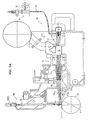
- Figure 1A is a sectional view of the headbox of a paper/board machine, and what is shown is the arrangement of supply of dilution liquid in connection with the tube manifold placed after the inlet header.
- Figure 1B is an illustration in part of the construction of Fig. 1A from above.
- Figure 1C shows the set of valves V 1 , V 2 ... for the regulation of the dilution liquid viewed in the direction of the arrow K 1 in Fig. 1A.
- Figure 2 is a sectional view taken along the line I ⁇ I in Fig. 1B. What is shown is the supply of dilution liquid into connection with the tube manifold on a larger scale.
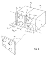
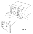
- Figure 3 is an axonometric view of modular construction components M 1 and M 2 .
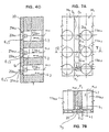
- Figure 4A is an illustration in part of the module M 1 shown in Fig. 3 viewed in the area of the tube manifold in the direction of the arrow K 2 in Fig. 3.
- Figure 4B is a sectional view taken along the line II ⁇ II in Fig. 4A.
- Figure 4C is a sectional view taken along the line III ⁇ III in Fig. 4A.
- Figure 4D shows a throttle plate placed at the outlet side of the tube manifold (in the flow direction of the stock). The illustration is substantially similar to the sectional view shown in Fig. 4B.
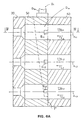
- Figure 5 shows an embodiment of the invention which is in the other respects similar to the sectional view of Fig. 4C, except that in this embodiment the branch ducts E 1.1 ,E 1.2 ,E 1.3 have been milled into the construction so that the flow is directed against the stock flow L 1 . In this way the mixing of the flows can be made efficient.
- Figure 6A shows a second embodiment of the arrangement of supply of dilution liquid.
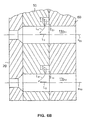
- Figure 6B is a sectional view taken along the line IV ⁇ IV in Fig. 6A.
- Figure 7A shows an embodiment of the invention in which one structural wall of the conically narrowing duct D 1 is formed by a side wall of an adjacent module.
- Figure 7B is a sectional view taken along the line V ⁇ V in Fig. 7A.
- Figure 8A shows an embodiment of the invention in which the supply of the dilution liquid into the stock flow takes place in the turbulence generator after an intermediate chamber.
- Figure 8B shows the construction of Fig. 8A viewed from above.
- Figure 9 shows an embodiment of the construction in accordance with the invention in which the stock ducts and the dilution liquid ducts have been made into one single plate by machining.
- the plate extends across the entire width of the headbox.
- the headbox 10 of the paper/board machine comprises an inlet header J, after the inlet header J a system of pipes, i.e. a set of pipes 11 of the tube manifold, which produces turbulence in the stock flow, and after the set of pipes an intermediate chamber 12, which is opened into the stilling chamber 13.
- a system of pipes i.e. a set of pipes 11 of the tube manifold
- an intermediate chamber 12 which is opened into the stilling chamber 13.
- the intermediate chamber 12 there is a second set of pipes which produces turbulence in the stock flow, i.e. the turbulence generator G.
- the pipes G 1.1 ,G 1.2 ... in the turbulence generator G are further opened into the slice cone 16, which comprises lamellae 17a 1 ,17a 2 ,17a 3 in the way shown in the figure.
- the outflow opening after the slice cone 16 comprises a top slice bar n and a mechanism 18 for its regulation.
- the position of the top slice bar n can be regulated by means of the adjustment spindles 19 and adjustment motors 20 included in the regulation mechanism 18.
- the flow L 1 of the dilution liquid is regulated by means of the valves V 1 ,V 2 ...
- the equipment comprises a number of distribution ducts D 1 ,D 2 ...
- the desired dilution flows can be introduced into different locations of width across the headbox, and said flows can be regulated at each location of width by regulating the valve V 1 , V 2 ... of the dilution flow.
- the dilution liquid preferably dilution water
- the dilution liquid is passed into different locations of width across the headbox of the paper machine so that the dilution water is passed into the pipes 11a 1.1 ,11a 1.2 ,11a 1.3 ;11a 2.1 ,11a 2.2 ,11a 2.3 ; 11a 3.1 ,11a 3.2 ,11a 3.3 ... in each vertical row in the tube manifold 11.
- Fig. 1B illustrates the construction as shown in Fig. 1A viewed from above.
- Fig. 1C illustrates the system of valves V 1 ,V 2 ,V 3 ... used in the regulation of the dilution liquid.
- the dilution liquid is passed from the dilution liquid inlet header J 2 into the dilution liquid supply ducts D 1 ,D 2 ... through the valves V 1 ,V 2 ...
- the flow of the dilution liquid L 1 is regulated in each duct D 1 ,D 2 ... independently from the other ducts.
- Fig. 2 is a sectional view taken along the line I ⁇ I in Fig. 1B.
- a stock flow L 1 is passed into each pipe 11a 1.1 , 11a 1.2 ,11a 1.3 ;11a 2.1 ,11a 2.2 ,11a 2.3 ; 11a 3.1 ,11a 3.2 ,11a 3.3 ... in the tube manifold 11.
- the dilution liquid is passed as a dilution flow L 2 into each pipe 11a 1.1 ,11a 1.2 , 11a 1.3 in a vertical row in the tube manifold.
- the flow is passed through the distribution duct D 1 or equivalent of the distribution pipe into the vertical row in the tube manifold 11 and further into each pipe 11a 1.1 ,11a 1.2 ,11a 1.3 in each vertical row.
- the dilution flow is passed out of the distribution ducts D 2 ,D 3 ... into the pipes 11a 2.1 ,11a 2.2 ,11a 2.3 ;11a 3.1 ,11a 3.2 ,11a 3.3 ... in the vertical rows at corresponding locations in the tube manifold 11.
- the distribution duct D 1 ,D 2 for dilution flow becomes narrower at its end so that the narrowing of the duct D 1 takes place towards the lowest pipe 11a 1.3 in the tube manifold 11.
- the duct portion D 1a of the duct D 1 which has been formed between the rows of pipes in the system of pipes, has additionally been formed so that its wall portion S 1 is placed as inclined in relation to the vertical plane.
- the branch ducts are opened from the wall S 2 of the duct portion D 1a into the pipes 11a 1.1 , 11a 1.2 ... in the vertical rows in the set of pipes 11.
- the pressure can be kept invariable in all the outlets E 1.1 ,E 1.2 ,E 1.3 of the duct D 1 .
- the cross-sectional shape of the distribution ducts E 1.1 ,E 1.2 ,E 1.3 branched from the dilution flow duct D 1 is rectangular.
- the cross-sectional shape of the end D 1a of the duct D 1 is rectangular, and said narrowing duct shape is produced by milling the end wall S 1 , which is placed inclined in relation to the vertical plane, in the end area of the duct D 1 .
- the duct D 1 portion D 1a is connected with a resilient flexible duct portion D 1b , which comprises a regulation valve V 1 at its end.
- the dilution liquid is passed into the duct D 1 out of the dilution liquid inlet header J 2 .
- the outlets of the branch ducts E 1.1 ,E 1.2 ,E 1.3 into the pipes 11a 1.1 ,11a 1.2 ,11a 1.3 in the tube manifold 11 are placed at the forward side of the throttle 21a 1.1 ,21a 1.2 , 21a 1.3 in relation to the flow direction L 1 .
- the throttle 21a 1.1 ,21a 1.2 ,21a 1.3 is a conical contraction of the duct, which terminates in a straight duct portion 22a 1.1 , 22a 1.2 ,22a 1.3 (FIG. 4D).
- the most usual embodiment is a construction in which there is one single plate into which the pipes 11a 1.1 ,11a 1.2 ,11a 1.3 ...; 11a 2.1 ,11a 2.2 , 11a 2.3 ... formed into said plate of the tube manifold 11 have been made by drilling, the branch ducts E 1.1 ,E 1.2 ,E 1.3 having been made into the front face T' of said plate by machining.
- the pipes 11a 1.1 ,11a 1.2 ,11a 1.3 ...; 11a 2.1 ,11a 2.2 , 11a 2.3 ... in the tube manifold 11 consist of two portions of sets of pipes, i.e. of pipes that have been machined, preferably drilled, into a separate plate and of separate pipe components connected with said pipes.
- Fig. 3 illustrates the modular structural components M 1 and M 2 in the mixing part of the tube manifold 11.
- the structural components or modules M 1 ,M 2 ... are preferably metallic plates T, into which the pipes 11a 1.1 ,11a 1.2 ,11a 1.3 in the initial part of the tube manifold 11 have been made by drilling into the plate T.
- the ducts D 1 , D 2 ... can be made into it, onto the front faces T' of the modules M 1 ,M 2 ..., easily by milling.
- the duct D 1 ,D 2 shape narrowing towards the end in the end portions D 1a ,D 2a ...
- the branch ducts E 1.1 ,E 1.2 ,E 1.3 ...; E 2.1 ,E 2.2 ,E 2.3 ...; E 3.1 ,E 3.2 ,E 3.3 ... can be made easily by milling into the front wall T' of the plate T of each module M 1 ,M 2 ...
- the ducts E 1.1 ,E 1.2 ,E 1.3 are placed perpendicularly to the central axes X 1.1 ,X 1.2 ,X 1.3 of the pipes 11a 1.1 ,11a 1.2 ,11a 1.3 in the tube manifold.
- the flows L 1 and L 2 meet each other at a right angle.
- Fig. 4A shows the module M 1 viewed in the direction of the arrow K 2 in Fig. 3.
- Fig. 4B is a sectional view taken along the line II ⁇ II in Fig. 4A.
- Fig. 4C is a sectional view taken along the line III ⁇ III in Fig. 4A.
- Figs. 4B and 4C do not show the throttle plate 20, but the fitting of said plate in connection with the construction is illustrated in Fig. 4D.
- Fig. 4D shows the throttle plate 20 in connection with the front part, i.e. the plate T, in the tube manifold 11.
- the separate pipes in the final part of the tube manifold 11 are placed, as is shown in Fig. 2.
- Fig. 5 shows a second embodiment of the invention, which is in the other respects similar to the sectional view in Fig. 4C, except that in said embodiment the branch ducts E 1.1 ,E 1.2 ,E 1.3 have been milled into the construction so that the flow direction of the flow L 1 out of the duct D 1 can be directed so that it is oblique against the flow L 2 coming from the inlet header J 1 . In such a case the mixing of the dilution flow L 1 and the stock flow L 2 can be made efficient.
- Fig. 5 is mainly similar to the sectional view in Fig. 4C.
- Fig. 6A shows an embodiment of the invention in which the duct portions D 1a , D 2a ... of the ducts D 1 ,D 2 ... have been formed into a construction plate 50, which is placed alongside the throttle plate 20 and so that the narrowing duct portion D 1a , D 2a ... is fitted to be opened so from the front face T" of the plate 50 that the cleaning of the duct system D 1a ,D 2a ...
- a separate plate 60 which contains the initial part of the system of flow ducts (11a 1.1 ,11a 1.2 ...; 11a 2.1 ,11a 2.2 ...; G 1.1 ,G 1.2 ...; G 2.1 ,G 2.2 ...) intended for the flow L 2 coming from the inlet header J 1 .
- the narrowing ducts D 1a ,D 2a ... and the connected branch ducts E 1.1 ,E 1.2 ... are opened for cleaning, and the extension portion D 1b ,D 2b ... connected with the narrowing duct D 1a ,D 2a ... does not interfere with the washing of the system of ducts, but said washing can be carried out by detaching the plate 60.
- Fig. 6B is a sectional view taken along the line IV ⁇ IV in Fig. 6A.
- Fig. 7A illustrates a plate-like module M 1 ,M 2 in accordance with the invention.
- the illustration in Fig. 7A is taken mainly in the direction of the arrow K 2 in Fig. 3.
- the embodiment of Fig. 7A differs from that of Fig. 3 mainly in the respect that one side wall of the adjacent modular structural components, i.e. of the modules M 1 ,M 2 , is defined by the duct D 1 ,D 2 ...
- one wall S 4 of the conical portion D 1a ,D 2a ... of the duct D 1 ,D 2 ... is formed by one side wall F 1 of the module M 2 adjacent to said module M 1 .
- the initial part of the tube manifold 11 has been formed out of plate-like modules M 1 ,M 2 ,M 3 ... by interconnecting said modules M 1 ,M 2 ,M 3 ... in the direction of width of the headbox of the paper/board machine.
- Fig. 7B is a sectional view taken along the line V ⁇ V in Fig. 7A.
- Fig. 8A shows an embodiment of the invention in which the mixing of the dilution liquid and the stock flow takes place after the intermediate chamber 12 in the turbulence generator G at the forward end of its pipes G 1.1 ,G 1.2 ,G 1.3 ...; G 2.1 ,G 2.2 , G 2.3 ... in a way similar to the solution described above.
- Fig. 8B shows the construction of Fig. 8A viewed from above in the area of the forward end of the turbulence generator G.
- Fig. 9 is an illustration in part of an embodiment of the invention which comprises narrowing ducts D 1 ,D 2 ... for dilution liquid in connection with a tube manifold 11 composed of a single plate-like structural component T.
- the pipes in the tube manifold 11 can have been made into a metallic plate construction conventionally by machining, preferably drilling.
- the ducts D 1 ,D 2 ... that supply dilution liquid have been made into the front face of the plate construction T, as was the case in the embodiments described above, by milling or by means of some other method of machining.
- the plate T extends across the entire width of the headbox.
- the construction can also be used in connection with the turbulence generator, after the intermediate chamber, or it can be used in a headbox construction which comprises, after the inlet header J 1 , just one system of pipes that produces turbulence and, after that, the slice cone.
Landscapes
- Paper (AREA)
- Preparation Of Clay, And Manufacture Of Mixtures Containing Clay Or Cement (AREA)
- Feeding, Discharge, Calcimining, Fusing, And Gas-Generation Devices (AREA)
Applications Claiming Priority (3)
| Application Number | Priority Date | Filing Date | Title |
|---|---|---|---|
| FI962567A FI98938C (fi) | 1996-06-20 | 1996-06-20 | Laitteisto laimennusvirtauksen yhdistämiseksi paperikoneen/kartonkikoneen jakotukista johdettuun massavirtaukseen |
| FI962567 | 1996-06-20 | ||
| PCT/FI1997/000386 WO1997048851A1 (en) | 1996-06-20 | 1997-06-18 | Equipment for combining a dilution flow with the stock flow passed out of the inlet header in a paper/board machine |
Publications (2)
| Publication Number | Publication Date |
|---|---|
| EP0907790A1 EP0907790A1 (en) | 1999-04-14 |
| EP0907790B1 true EP0907790B1 (en) | 2003-03-12 |
Family
ID=8546255
Family Applications (1)
| Application Number | Title | Priority Date | Filing Date |
|---|---|---|---|
| EP97927205A Expired - Lifetime EP0907790B1 (en) | 1996-06-20 | 1997-06-18 | Equipment for combining a dilution flow with the stock flow passed out of the inlet header in a paper/board machine |
Country Status (9)
| Country | Link |
|---|---|
| US (1) | US5814191A (https=) |
| EP (1) | EP0907790B1 (https=) |
| JP (1) | JP3803384B2 (https=) |
| CN (1) | CN1075851C (https=) |
| AT (1) | ATE234387T1 (https=) |
| AU (1) | AU3177797A (https=) |
| DE (1) | DE69719756T2 (https=) |
| FI (1) | FI98938C (https=) |
| WO (1) | WO1997048851A1 (https=) |
Families Citing this family (24)
| Publication number | Priority date | Publication date | Assignee | Title |
|---|---|---|---|---|
| FI115646B (fi) * | 1996-11-26 | 2005-06-15 | Metso Paper Inc | Paperikoneen/kartonkikoneen monikerrosperälaatikko |
| DE19654390A1 (de) * | 1996-12-27 | 1998-07-02 | Basf Ag | Verfahren zur Herstellung von Papier |
| US5944957A (en) * | 1997-03-14 | 1999-08-31 | Valmet Corporation | Regulations system in a paper machine for controlling variation of the basis weight of the paper in the machine direction |
| DE19736047A1 (de) | 1997-08-20 | 1999-02-25 | Voith Sulzer Papiermasch Gmbh | Vorrichtung und Verfahren zur Steuerung oder Regelung des Flächengewichts einer Papier- oder Kartonbahn |
| US6083351A (en) * | 1998-03-25 | 2000-07-04 | Voith Sulzer Paper Technology North America, Inc. | Dilution control device for a wet end of a paper-making machine |
| DE19922817A1 (de) * | 1999-05-19 | 2000-11-23 | Voith Sulzer Papiertech Patent | Vorrichtung und Verfahren zur Steuerung oder Regelung des Flächengewichts einer Papier- oder Kartonbahn |
| US6270625B1 (en) * | 1999-06-29 | 2001-08-07 | The Mead Corporation | Method for manufacturing colored stripped paper |
| FI113972B (fi) * | 2000-05-08 | 2004-07-15 | Metso Paper Inc | Paperikoneen, kartonkikoneen, sellukoneen tai vastaavan perälaatikko |
| GB2367564B (en) | 2000-10-04 | 2004-02-18 | Sandusky Walmsley Ltd | Method of and apparatus for distribution of paper stock in paper or board making machinery |
| DE10122047A1 (de) * | 2001-05-07 | 2002-11-14 | Voith Paper Patent Gmbh | Blattbildungsvorrichtung und -verfahren |
| DE102004000051A1 (de) * | 2004-11-19 | 2006-05-24 | Voith Paper Patent Gmbh | Stoffauflauf einer Maschine zur Herstellung einer Fasersstoffbahn |
| PL205833B1 (pl) * | 2005-04-26 | 2010-05-31 | Pmpoland Spo & Lstrok Ka Akcyj | Skrzynia wlewowa |
| DE102005051656A1 (de) * | 2005-10-28 | 2007-05-03 | Voith Patent Gmbh | Verfahren und Vorrichtung zur Herstellung einer Faserstoffbahn |
| ATE519098T1 (de) * | 2006-02-01 | 2011-08-15 | Astenjohnson Inc | Stofflauf und materialausgabesystem für eine papierherstellungsmaschine |
| CN101012629B (zh) * | 2006-05-31 | 2011-04-27 | 华南理工大学 | 流浆箱的稀释水添加装置 |
| ITFI20060267A1 (it) * | 2006-10-30 | 2008-04-30 | Toscotec S P A | Dispositivo per regolare il profilo di grammatura trasversale della carta |
| WO2008105714A1 (en) * | 2007-03-01 | 2008-09-04 | Metso Paper Karlstad Ab | Structural element for a functional member of a headbox in a web-manufacturing machine, functional member and headbox made thereof, and associated methods |
| DE102008000778A1 (de) | 2008-03-20 | 2009-09-24 | Voith Patent Gmbh | Stoffauflauf für eine Papier- oder Kartonmaschine |
| US7871493B2 (en) * | 2008-06-26 | 2011-01-18 | Kimberly-Clark Worldwide, Inc. | Environmentally-friendly tissue |
| DE102009014268B3 (de) * | 2009-03-20 | 2010-04-08 | Andritz Küsters Gmbh | Anordnung an Papiermaschinen zur Einstellung eines Flächengewichts-Querprofils |
| FI20115407A7 (fi) | 2011-04-28 | 2012-10-29 | Vaahto Oy | Paperikoneen perälaatikon yhteydessä oleva jakokanavisto |
| CN104074217A (zh) * | 2014-04-28 | 2014-10-01 | 三一重通机械有限公司 | 一种推土机单手柄转向制动控制系统及推土机 |
| DE102016114040A1 (de) * | 2016-07-29 | 2018-02-01 | Voith Patent Gmbh | Strömungsmodul und Verfahren zur Herstellung eines Strömungsmoduls für einen Stoffauflauf einer Papiermaschine |
| DE102017122538A1 (de) | 2017-09-28 | 2019-03-28 | Voith Patent Gmbh | Verfahren und Vorrichtung zur Herstellung eines Strömungselements |
Family Cites Families (19)
| Publication number | Priority date | Publication date | Assignee | Title |
|---|---|---|---|---|
| DE3514554C3 (de) * | 1984-09-19 | 1998-01-08 | Escher Wyss Gmbh | Stoffauflauf-Vorrichtung für eine Papiermaschine und Verfahren zu deren Betrieb |
| DE3741603A1 (de) * | 1987-12-09 | 1989-06-22 | Voith Gmbh J M | Stoffauflauf fuer eine papiermaschine od.dgl. |
| FR2631353A1 (fr) * | 1988-05-13 | 1989-11-17 | Semti | Dispositif d'alimentation en melange pateux |
| FI901593A7 (fi) * | 1990-03-30 | 1991-10-01 | Valmet Paper Machinery Inc | Menetelmä paperi- tai kartonkikoneessa perälaatikosta tulevan massan säätämiseksi sekä paperi- tai kartonkikoneen perälaatikko |
| DE4019593C2 (de) * | 1990-06-20 | 1994-01-20 | Voith Gmbh J M | Stoffauflauf für Papiermaschinen |
| US5196091A (en) * | 1991-10-29 | 1993-03-23 | Beloit Technologies, Inc. | Headbox apparatus with stock dilution conduits for basis weight control |
| DE4213707A1 (de) * | 1992-04-25 | 1993-10-28 | Escher Wyss Gmbh | Stoffauflaufeinrichtung für eine Papiermaschine |
| JP3021219B2 (ja) * | 1992-10-29 | 2000-03-15 | 三菱重工業株式会社 | 抄紙機ヘッドボックスの端部流量調整装置 |
| FI100894B (fi) * | 1993-07-01 | 1998-03-13 | Valmet Paper Machinery Inc | Menetelmä ja laite perälaatikon säädössä |
| FI92230C (fi) * | 1993-07-01 | 1994-10-10 | Valmet Paper Machinery Inc | Menetelmä monikerrosperälaatikon säädössä ja monikerrosperälaatikko |
| EP1099793B1 (en) * | 1993-07-01 | 2006-08-02 | Metso Paper, Inc. | Method and device in the regulation of the headbox |
| DE4323263C2 (de) * | 1993-07-12 | 2001-11-29 | Voith Paper Patent Gmbh | Verfahren zur sektionalen Beeinflussung der Stoffdichte und der Faserorientierung in einem Stoffauflauf einer Papiermaschine und Stoffauflauf zur Durchführung des Verfahrens |
| DE4416898C2 (de) * | 1994-05-13 | 1996-03-28 | Voith Sulzer Papiermasch Gmbh | Stoffauflauf für eine Papiermaschine mit lokaler Zumischung von Fluid |
| US5549793A (en) * | 1994-08-02 | 1996-08-27 | Abb Industrial Systems, Inc. | Control of dilution lines in a dilution headbox of a paper making machine |
| US5560807A (en) * | 1995-03-29 | 1996-10-01 | Beloit Technologies, Inc. | Headbox additive injection system |
| US5626722A (en) * | 1995-06-01 | 1997-05-06 | Valmet Corporation | Headbox of a paper/board machine |
| US5603806A (en) * | 1995-06-01 | 1997-02-18 | Valmet Corporation | Method and apparatus for lateral alignment of the cross-direction quality profile of a web in a paper machine |
| FI110879B (fi) * | 1996-10-23 | 2003-04-15 | Metso Paper Inc | Laitteisto laimennusnesteen virtauksen säädössä paperikoneen/kartonkikoneen perälaatikon yhteydessä |
| FI115645B (fi) * | 1997-01-14 | 2005-06-15 | Metso Paper Inc | Paperikoneen perälaatikko, jossa on reunasyöttöjärjestelyt |
-
1996
- 1996-06-20 FI FI962567A patent/FI98938C/fi not_active IP Right Cessation
-
1997
- 1997-06-18 CN CN97195660A patent/CN1075851C/zh not_active Expired - Fee Related
- 1997-06-18 DE DE69719756T patent/DE69719756T2/de not_active Expired - Lifetime
- 1997-06-18 AT AT97927205T patent/ATE234387T1/de active
- 1997-06-18 JP JP50238898A patent/JP3803384B2/ja not_active Expired - Fee Related
- 1997-06-18 AU AU31777/97A patent/AU3177797A/en not_active Abandoned
- 1997-06-18 EP EP97927205A patent/EP0907790B1/en not_active Expired - Lifetime
- 1997-06-18 WO PCT/FI1997/000386 patent/WO1997048851A1/en not_active Ceased
- 1997-06-20 US US08/879,597 patent/US5814191A/en not_active Expired - Lifetime
Also Published As
| Publication number | Publication date |
|---|---|
| FI98938B (fi) | 1997-05-30 |
| CN1075851C (zh) | 2001-12-05 |
| DE69719756T2 (de) | 2003-11-06 |
| JP2000512696A (ja) | 2000-09-26 |
| FI98938C (fi) | 1997-09-10 |
| CN1222209A (zh) | 1999-07-07 |
| DE69719756D1 (de) | 2003-04-17 |
| FI962567A0 (fi) | 1996-06-20 |
| AU3177797A (en) | 1998-01-07 |
| WO1997048851A1 (en) | 1997-12-24 |
| JP3803384B2 (ja) | 2006-08-02 |
| EP0907790A1 (en) | 1999-04-14 |
| ATE234387T1 (de) | 2003-03-15 |
| US5814191A (en) | 1998-09-29 |
Similar Documents
| Publication | Publication Date | Title |
|---|---|---|
| EP0907790B1 (en) | Equipment for combining a dilution flow with the stock flow passed out of the inlet header in a paper/board machine | |
| FI115645B (fi) | Paperikoneen perälaatikko, jossa on reunasyöttöjärjestelyt | |
| EP1099793B1 (en) | Method and device in the regulation of the headbox | |
| EP0745722B1 (en) | Headbox of a paper/board machine | |
| EP0635600B1 (en) | Method and device for regulating a headbox | |
| US8303774B2 (en) | Headbox for a machine for producing a fibrous web | |
| EP0943033B1 (en) | Multi-layer headbox for a paper machine/board machine | |
| JPH093788A (ja) | 多層ヘッドボックスの紙料供給システムおよび多層ヘッドボックスの操作方法 | |
| CA1204614A (en) | Flow rectifier | |
| US6030500A (en) | Arrangement for feeding stock to a headbox in a papermaking machine | |
| US5000227A (en) | Pressurized fluid carrier conduit connection | |
| US5900121A (en) | Dosing feeder for the breast box of papermaking machine | |
| CA2258232C (en) | Equipment for combining a dilution flow with the stock flow passed out of the inlet header in a paper/board machine | |
| KR100488866B1 (ko) | 제지기/판지초지기의입구헤더를통과하는지료유동과희석유동을결합하는장치 | |
| WO1995008024A1 (en) | A method for controlling the orientation of fibers | |
| US5800678A (en) | Method and device for regulating a flow of dilution liquid in connection with a headbox of a paper/board machine | |
| US4885060A (en) | Papermachine headbox profiling bar with fluid discharge orifices along its length | |
| EP0912797B1 (en) | An arrangement for feeding stock to a headbox in a papermaking machine | |
| US6083351A (en) | Dilution control device for a wet end of a paper-making machine | |
| US20070056708A1 (en) | Apparatus in connection with a headbox of a paper machine or equivalent | |
| US5938896A (en) | Hydraulic increaser for a wet end of a paper-making machine | |
| US5888353A (en) | Flatsided parabolic header for headboxes | |
| FI101555B (fi) | Laitteisto laimennusvirtauksen yhdistämiseksi paperikoneen/kartonkikon een jakotukista johdettuun massavirtaukseen | |
| FI110528B (fi) | Laitteisto paperikoneen/kartonkikoneen perälaatikon yhteydessä | |
| FI97738B (fi) | Paperi- tai kartonkikoneen perälaatikko |
Legal Events
| Date | Code | Title | Description |
|---|---|---|---|
| PUAI | Public reference made under article 153(3) epc to a published international application that has entered the european phase |
Free format text: ORIGINAL CODE: 0009012 |
|
| 17P | Request for examination filed |
Effective date: 19981210 |
|
| AK | Designated contracting states |
Kind code of ref document: A1 Designated state(s): AT DE FR GB IT SE |
|
| 17Q | First examination report despatched |
Effective date: 20010613 |
|
| RAP1 | Party data changed (applicant data changed or rights of an application transferred) |
Owner name: METSO PAPER, INC. |
|
| GRAG | Despatch of communication of intention to grant |
Free format text: ORIGINAL CODE: EPIDOS AGRA |
|
| GRAG | Despatch of communication of intention to grant |
Free format text: ORIGINAL CODE: EPIDOS AGRA |
|
| GRAH | Despatch of communication of intention to grant a patent |
Free format text: ORIGINAL CODE: EPIDOS IGRA |
|
| GRAH | Despatch of communication of intention to grant a patent |
Free format text: ORIGINAL CODE: EPIDOS IGRA |
|
| GRAA | (expected) grant |
Free format text: ORIGINAL CODE: 0009210 |
|
| AK | Designated contracting states |
Designated state(s): AT DE FR GB IT SE |
|
| REG | Reference to a national code |
Ref country code: GB Ref legal event code: FG4D |
|
| REF | Corresponds to: |
Ref document number: 69719756 Country of ref document: DE Date of ref document: 20030417 Kind code of ref document: P |
|
| REG | Reference to a national code |
Ref country code: SE Ref legal event code: TRGR |
|
| ET | Fr: translation filed | ||
| PLBE | No opposition filed within time limit |
Free format text: ORIGINAL CODE: 0009261 |
|
| STAA | Information on the status of an ep patent application or granted ep patent |
Free format text: STATUS: NO OPPOSITION FILED WITHIN TIME LIMIT |
|
| 26N | No opposition filed |
Effective date: 20031215 |
|
| PGFP | Annual fee paid to national office [announced via postgrant information from national office to epo] |
Ref country code: GB Payment date: 20090618 Year of fee payment: 13 |
|
| GBPC | Gb: european patent ceased through non-payment of renewal fee |
Effective date: 20100618 |
|
| PG25 | Lapsed in a contracting state [announced via postgrant information from national office to epo] |
Ref country code: GB Free format text: LAPSE BECAUSE OF NON-PAYMENT OF DUE FEES Effective date: 20100618 |
|
| PGFP | Annual fee paid to national office [announced via postgrant information from national office to epo] |
Ref country code: FR Payment date: 20120705 Year of fee payment: 16 Ref country code: SE Payment date: 20120621 Year of fee payment: 16 |
|
| PGFP | Annual fee paid to national office [announced via postgrant information from national office to epo] |
Ref country code: IT Payment date: 20130624 Year of fee payment: 17 |
|
| PG25 | Lapsed in a contracting state [announced via postgrant information from national office to epo] |
Ref country code: SE Free format text: LAPSE BECAUSE OF NON-PAYMENT OF DUE FEES Effective date: 20130619 |
|
| REG | Reference to a national code |
Ref country code: SE Ref legal event code: EUG |
|
| REG | Reference to a national code |
Ref country code: FR Ref legal event code: ST Effective date: 20140228 |
|
| PG25 | Lapsed in a contracting state [announced via postgrant information from national office to epo] |
Ref country code: FR Free format text: LAPSE BECAUSE OF NON-PAYMENT OF DUE FEES Effective date: 20130701 |
|
| PGFP | Annual fee paid to national office [announced via postgrant information from national office to epo] |
Ref country code: AT Payment date: 20140611 Year of fee payment: 18 |
|
| PG25 | Lapsed in a contracting state [announced via postgrant information from national office to epo] |
Ref country code: IT Free format text: LAPSE BECAUSE OF NON-PAYMENT OF DUE FEES Effective date: 20140618 |
|
| PGFP | Annual fee paid to national office [announced via postgrant information from national office to epo] |
Ref country code: DE Payment date: 20150619 Year of fee payment: 19 |
|
| REG | Reference to a national code |
Ref country code: AT Ref legal event code: MM01 Ref document number: 234387 Country of ref document: AT Kind code of ref document: T Effective date: 20150618 |
|
| PG25 | Lapsed in a contracting state [announced via postgrant information from national office to epo] |
Ref country code: AT Free format text: LAPSE BECAUSE OF NON-PAYMENT OF DUE FEES Effective date: 20150618 |
|
| REG | Reference to a national code |
Ref country code: DE Ref legal event code: R119 Ref document number: 69719756 Country of ref document: DE |
|
| PG25 | Lapsed in a contracting state [announced via postgrant information from national office to epo] |
Ref country code: DE Free format text: LAPSE BECAUSE OF NON-PAYMENT OF DUE FEES Effective date: 20170103 |