EP0907198A2 - Verbindungsvervahren und -Struktur eines elektronischen Bauteils an eines elektromagnetisches Relais - Google Patents
Verbindungsvervahren und -Struktur eines elektronischen Bauteils an eines elektromagnetisches Relais Download PDFInfo
- Publication number
- EP0907198A2 EP0907198A2 EP98118541A EP98118541A EP0907198A2 EP 0907198 A2 EP0907198 A2 EP 0907198A2 EP 98118541 A EP98118541 A EP 98118541A EP 98118541 A EP98118541 A EP 98118541A EP 0907198 A2 EP0907198 A2 EP 0907198A2
- Authority
- EP
- European Patent Office
- Prior art keywords
- electrical component
- electromagnetic relay
- lead
- recited
- legs
- Prior art date
- Legal status (The legal status is an assumption and is not a legal conclusion. Google has not performed a legal analysis and makes no representation as to the accuracy of the status listed.)
- Granted
Links
Images


Classifications
-
- H—ELECTRICITY
- H01—ELECTRIC ELEMENTS
- H01H—ELECTRIC SWITCHES; RELAYS; SELECTORS; EMERGENCY PROTECTIVE DEVICES
- H01H50/00—Details of electromagnetic relays
- H01H50/44—Magnetic coils or windings
- H01H50/443—Connections to coils
-
- H—ELECTRICITY
- H01—ELECTRIC ELEMENTS
- H01H—ELECTRIC SWITCHES; RELAYS; SELECTORS; EMERGENCY PROTECTIVE DEVICES
- H01H50/00—Details of electromagnetic relays
- H01H50/02—Bases; Casings; Covers
- H01H50/021—Bases; Casings; Covers structurally combining a relay and an electronic component, e.g. varistor, RC circuit
Definitions
- the present invention relates to electromagnetic relay assembly structure and methods and, more particularly, to structure and methods for the connection of electrical components to terminals of electromagnetic relays.
- Electromagnetic relays are known and widely used throughout the electronics industry. Electromagnetic relays generally include a bobbin, a coil wound thereon, a core, an armature, a movable contact and at least one stationary contact. These components are assembled to form an electromagnet block. The electromagnet block, together with the remaining components, are mounted on a base. The base also provides a receptacle for electrically connecting terminals from the contacts and electromagnet block to control and load circuits. A cover is typically placed over the relay, engageable with the base, to form a closed casing.
- the disclosed relay incorporates various structure and utilizes various methods during assembly of the relay, to reduce the time and costs associated with the manufacturing process and provide a more reliable relay.
- the present disclosure provides an electromagnetic relay which includes a base defining a bottom plane; an electromagnet assembly mounted on the base, the electromagnet assembly comprising a bobbin, a core and at least one winding about the core; an armature supported to be movable about a predetermined point for movement between two contact operating positions; at least one contact assembly for selectively providing one of an open and closed circuit, the contact assembly including at least one movable contact and at least one stationary contact; and at least two terminal members mounted on the base having distal ends for electrically connecting at least two ends of the winding with a source of energy, and proximal ends including a pair of depending legs forming a slot therebetween for receiving at least one lead of an electrical component, such as a resistor or a diode.
- an electrical component such as a resistor or a diode.
- the present disclosure further provides an electromagnetic relay wherein the pair of depending legs are configured to be mechanically crimped to secure the leads of the electrical component within a portion of the slot.
- the present disclosure still further provides a terminal member for electrically connecting coil winding leads of an electromagnetic relay to a power supply which includes an elongate strip of electrically conductive material having a pair of depending legs forming a slot on a proximal end thereof, wherein the slot is configured to receive at least one lead of an electrical component, such as a resistor or a diode.
- the present disclosure yet further provides a terminal member for electrically connecting coil winding leads of an electromagnetic relay to a power supply wherein the pair of depending legs are configured to be mechanically crimped to secure at least one lead of an electrical component within a portion of a slot formed therebetween.
- the present disclosure still yet further provides a method of assembling an electromagnetic relay which includes the steps of placing an electromagnet block having a bobbin, a core and at least one winding about the core on a base; supporting an armature for movement about a predetermined point for and between two contact operating positions; placing at least one contact assembly for selectively providing one of an open and closed circuit on the base; inserting at least two terminal members in the base for electrically connecting at least two ends of the winding with a source of energy at a distal end thereof; placing at least one lead of an electrical component in a slot formed by a pair of legs extending from proximal ends of the two terminal members and securing the leads of an electrical component in the slot formed by the pair of legs extending from proximal ends of the two terminal members by mechanically crimping the pair of legs.
- FIGS. 1-4 illustrate embodiments of electromagnetic relays having coil terminal members configured and dimensioned in accordance with the present invention. As will be discussed in further detail below, the two embodiments advantageously allow the insertion of an electronic component and the crimping operation to be performed from various directions.
- relay 50 comprises a base 52 which defines a main or bottom plane for the relay.
- An electromagnet assembly is mounted on base 52 and comprises a bobbin 54, a core, at least one winding about bobbin 54 and an armature.
- Stationary and movable contacts 56 and 58 are configured to selectively provide one of an open and closed circuit in response to energization signals received by the electromagnet assembly. That is, when the electromagnet assembly is energized, it causes movement of the armature which in turn moves movable contact 58 into or out of engagement with stationary contact 56.
- a plurality of terminals are insertably received in the lower portion of base 52, to electrically connect the stationary and movable contacts and the electromagnet assembly with corresponding control and load circuits.
- Contact terminals are designated as numeral 60 and coil terminals are designated as numeral 62.
- Each of the terminals are typically inserted into slots in the base and are fixed by caulking, epoxy or by any other suitable sealant or method.
- the terminals extend substantially perpendicular from the linear plane of base 52.
- the electromagnet assembly typically comprises a bobbin 54 having at least one coil winding thereon.
- the winding commences and ends with terminal ends which are electrically connected to a load circuit through terminals 62.
- an electrical component 66 such as a resistor or diode, is commonly connected across coil terminals 62.
- Conventional means for connecting electrical components 66 include welding or soldering.
- terminals 62 include a pair of legs 68 extending from a proximal end which form a slot therebetween. Therefore, during assembly of the relay, an electrical component 66 may simply be connected to coil terminals 62 by inserting the leads of component 66 in the slot formed by legs 68. As will be discussed in further detail below, in accordance with the present invention, leads of component 66 may be secured between legs 68 by an interference fit or by mechanically crimping legs 68.
- legs 68 may vary. As illustrated in FIGS. 1 and 2, legs 68 extend in a direction along the longitudinal axis of terminals 62 such that electrical component 66 may be placed in the slot formed by legs 68 from the top. This configuration will also provide access to legs 68 in the same direction for a crimping tool.
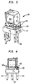
- FIGS. 3 and 4 illustrate another embodiment of a relay having terminals configured in accordance with the present invention.
- electromagnetic relay 150 comprises a base 152 which defines a main or bottom plane for the relay.
- An electromagnet assembly is mounted on base 152 and comprises a bobbin 154, a core, at least one winding about bobbin 154 and an armature.
- Stationary and movable contacts 156 and 158, respectively, are configured to selectively provide one of an open and closed circuit in response to energization signals received by the electromagnet assembly. That is, when the electromagnet assembly is energized, it causes movement of the armature which in turn moves movable contact 158 into or out of engagement with stationary contact 156.
- a plurality of terminals are insertably received in the lower portion of base 152, to electrically connect the stationary and movable contacts and the electromagnet assembly with corresponding control and load circuits.
- Contact terminals are designated as numeral 160 and coil terminals are designated as numeral 162.
- Each of the terminals are typically inserted into slots in the base and are fixed by caulking, epoxy or by any other suitable sealant or method.
- the terminals extend substantially perpendicular from the linear plane of base 152.
- the electromagnet assembly typically comprises a bobbin 154 having at least one coil winding thereon.
- the winding commences and ends with terminal ends which are electrically connected to a load circuit through terminals 162.
- an electrical component 166 such as a resistor or diode, is commonly connected across coil terminals 162.
- Conventional means for connecting electrical components 166 include welding or soldering.
- terminals 162 include a pair of legs 168 extending from a proximal end which form a slot therebetween. Therefore, during assembly of the relay, an electrical component 166 may simply be connected to coil terminals 162 by inserting the leads of component 166 in the slot formed by legs 168. As will be discussed in further detail below, in accordance with the present invention, leads of component 166 may be secured between legs 168 by an interference fit or by mechanically crimping legs 168.
- terminals 162 of relay 150 are illustrative of an alternative embodiment wherein legs 168 extend in a direction which is substantially perpendicular to the longitudinal axis of terminals 162 such that electrical component 166 may be placed in the slot formed by legs 168 from the side.
- terminal 200 is configured such that a vertical slot 208 is formed by legs 204, to accept a lead 210 of an electrical component 212 which is moved in a direction which is substantially perpendicular to the longitudinal axis of the terminal, as indicated by the arrow.
- terminal 202 is configured such that a substantially horizontal slot 214 is formed by legs 216 extending therefrom, to accept a lead 216 of an electrical component 218 which is moved in a substantially horizontal direction along the longitudinal axis of the terminal, as indicated by the arrow.
- the embodiments of the terminals will accommodate varying manufacturing processes and apparatus.
- FIGS. 7 and 8 illustrate alternative embodiments of crimping tools 230 and 232 which may be utilized to crimp legs 234 and 236 extending from terminals 238 and 240 to secure leads 242 and 244 of an electrical component.
- Legs 246 and 248 extend from crimping tool 230 and 232, respectively, and are configured to receive terminal legs 234 and 236 therebetween such that a force exerted by the crimping tool against the terminal legs will cause the terminal legs to move toward each other.
- the configuration of the terminal legs and crimp tool facilitate crimping of the terminal legs by a simple motion.
- a crimp tool which requires a hinge motion is not required.
- a plurality of configurations of terminal legs are contemplated, as illustrated in FIGS. 9-26.
- a vertical slot may be formed by a single leg 302 adjacent an end of a horizontal terminal member 300 as illustrated in FIGS. 9-11.
- a crimp tool having one leg 304 extending therefrom may be used to engage the single terminal leg 302 and force it against the terminal body portion to secure a lead 306 of an electrical component.
- FIGS. 12-26 illustrate legs extending from terminals in the substantially vertical or horizontal direction to receive an electrical component lead from a corresponding vertical or horizontal direction as discussed above with reference to FIGS. 5 and 6.
- FIGS. 12-26 illustrate additional features associated with the terminal legs, in accordance with the present invention, which are designed to enhance the ability of the legs to secure a lead of an electrical component.
- the terminal legs in FIGS. 12-14 and 25 feature a tapered cross-sectional area of the slot formed by the legs. Therefore, as a lead is pressed into the slot it will experience an interference fit at a point within the slot wherein the cross-sectional area is less than the cross-sectional area of the lead.
- FIG. 18 illustrates a modified version of the configuration of FIGS. 12-14 and 25 wherein only a portion of one leg is tapered to provide an interference fit with a lead of an electrical component.
- FIG. 20 illustrates a step in the cross-sectional area of the slot to provide an interference fit for the lead.
- FIGS. 9, 11-13, 15 and 22-25 each illustrate a relief notch disposed in the inner surface of one or both of the terminal legs.
- the lead of the electrical component will experience interference as it enters the slot between the terminal legs. However, as the lead enters the area defined by the relief notch, it will drop into the notch and the resiliency of the terminal legs will hold the lead in a position within the notch. The terminal legs may then be crimped to further secure the lead.
- FIGS. 16, 17 and 19 illustrate terminal legs having at least one ridge on the inner surface to provide an interference fit for the lead as it is inserted into the slot formed between the legs.
- a single ridge may be utilized as illustrated in FIG. 19, or at least two ridges may be utilized in varying configurations as illustrated in FIGS. 16 and 17.
- the embodiment of the terminal illustrated in FIG. 26 is similar to the embodiments of FIGS. 9-11 in that the lead is held within a slot by crimping one leg portion.
- a sharp corner 310 formed on a side of the slot opposite the one leg advantageously helps to retain the lead within the slot during the crimping operation.
Landscapes
- Physics & Mathematics (AREA)
- Electromagnetism (AREA)
- Electromagnets (AREA)
- Connections Arranged To Contact A Plurality Of Conductors (AREA)
- Switch Cases, Indication, And Locking (AREA)
Applications Claiming Priority (2)
| Application Number | Priority Date | Filing Date | Title |
|---|---|---|---|
| US94299597A | 1997-10-02 | 1997-10-02 | |
| US942995 | 1997-10-02 |
Publications (3)
| Publication Number | Publication Date |
|---|---|
| EP0907198A2 true EP0907198A2 (de) | 1999-04-07 |
| EP0907198A3 EP0907198A3 (de) | 1999-08-25 |
| EP0907198B1 EP0907198B1 (de) | 2006-04-12 |
Family
ID=25478936
Family Applications (1)
| Application Number | Title | Priority Date | Filing Date |
|---|---|---|---|
| EP98118541A Expired - Lifetime EP0907198B1 (de) | 1997-10-02 | 1998-10-01 | Verbindungsverfahren und Verbindungsstruktur eines elektronischen Bauteils an einem elektromagnetischen Relais |
Country Status (6)
| Country | Link |
|---|---|
| US (1) | US6057749A (de) |
| EP (1) | EP0907198B1 (de) |
| JP (1) | JPH11162318A (de) |
| CN (1) | CN1138292C (de) |
| DE (1) | DE69834160T2 (de) |
| TW (1) | TW389924B (de) |
Cited By (1)
| Publication number | Priority date | Publication date | Assignee | Title |
|---|---|---|---|---|
| CN101950711A (zh) * | 2010-10-22 | 2011-01-19 | 厦门宏发电声股份有限公司 | 一种电磁继电器 |
Families Citing this family (9)
| Publication number | Priority date | Publication date | Assignee | Title |
|---|---|---|---|---|
| JP2002100275A (ja) | 2000-07-18 | 2002-04-05 | Nagano Fujitsu Component Kk | 電磁継電器 |
| JP4424042B2 (ja) * | 2004-04-06 | 2010-03-03 | 住友電装株式会社 | 車載用リレーおよび電気接続箱 |
| JP2006210018A (ja) * | 2005-01-25 | 2006-08-10 | Idec Corp | リレー用コイル端子およびリレー |
| ITPC20050005U1 (it) * | 2005-03-10 | 2006-09-11 | Electrica Srl | Rele' voltmetrico con connettori rigidi atti a collegare il filo della bobina ai terminali faston |
| JP4952324B2 (ja) * | 2007-03-22 | 2012-06-13 | オムロン株式会社 | 電磁継電器 |
| JP5447122B2 (ja) * | 2010-04-13 | 2014-03-19 | 株式会社デンソー | 電磁スイッチ |
| JP6428814B2 (ja) | 2017-03-14 | 2018-11-28 | オムロン株式会社 | トリガースイッチ |
| US10851754B2 (en) * | 2017-07-11 | 2020-12-01 | Borgwarner Inc. | Starter solenoid with dual coils and axial diodes |
| US11929224B2 (en) * | 2019-04-25 | 2024-03-12 | Xiamen Hongfa Automotive Electronics Co., Ltd. | Relay coil assembly |
Citations (4)
| Publication number | Priority date | Publication date | Assignee | Title |
|---|---|---|---|---|
| DE162179C (de) * | ||||
| GB883203A (en) * | 1957-05-16 | 1961-11-29 | Pressac Ltd | A metal tag for receiving the bared end or part of an electric conducting wire |
| DE3220405A1 (de) * | 1982-05-29 | 1983-12-01 | Standard Elektrik Lorenz Ag, 7000 Stuttgart | Steckmesser |
| DE3428595A1 (de) * | 1984-08-02 | 1986-02-20 | Siemens AG, 1000 Berlin und 8000 München | Elektromagnetisches relais |
Family Cites Families (3)
| Publication number | Priority date | Publication date | Assignee | Title |
|---|---|---|---|---|
| JPH02106662U (de) * | 1989-02-10 | 1990-08-24 | ||
| JP3255673B2 (ja) * | 1991-12-16 | 2002-02-12 | 自動車電機工業株式会社 | 電磁継電器 |
| JP3593774B2 (ja) * | 1996-01-09 | 2004-11-24 | オムロン株式会社 | 電磁継電器 |
-
1998
- 1998-10-01 EP EP98118541A patent/EP0907198B1/de not_active Expired - Lifetime
- 1998-10-01 DE DE69834160T patent/DE69834160T2/de not_active Expired - Lifetime
- 1998-10-02 CN CNB98122833XA patent/CN1138292C/zh not_active Expired - Fee Related
- 1998-10-02 JP JP10281541A patent/JPH11162318A/ja active Pending
- 1998-11-09 US US09/188,744 patent/US6057749A/en not_active Expired - Lifetime
- 1998-12-22 TW TW087116436A patent/TW389924B/zh not_active IP Right Cessation
Patent Citations (4)
| Publication number | Priority date | Publication date | Assignee | Title |
|---|---|---|---|---|
| DE162179C (de) * | ||||
| GB883203A (en) * | 1957-05-16 | 1961-11-29 | Pressac Ltd | A metal tag for receiving the bared end or part of an electric conducting wire |
| DE3220405A1 (de) * | 1982-05-29 | 1983-12-01 | Standard Elektrik Lorenz Ag, 7000 Stuttgart | Steckmesser |
| DE3428595A1 (de) * | 1984-08-02 | 1986-02-20 | Siemens AG, 1000 Berlin und 8000 München | Elektromagnetisches relais |
Cited By (1)
| Publication number | Priority date | Publication date | Assignee | Title |
|---|---|---|---|---|
| CN101950711A (zh) * | 2010-10-22 | 2011-01-19 | 厦门宏发电声股份有限公司 | 一种电磁继电器 |
Also Published As
| Publication number | Publication date |
|---|---|
| TW389924B (en) | 2000-05-11 |
| EP0907198B1 (de) | 2006-04-12 |
| DE69834160D1 (de) | 2006-05-24 |
| EP0907198A3 (de) | 1999-08-25 |
| CN1138292C (zh) | 2004-02-11 |
| DE69834160T2 (de) | 2007-01-04 |
| JPH11162318A (ja) | 1999-06-18 |
| CN1218971A (zh) | 1999-06-09 |
| US6057749A (en) | 2000-05-02 |
Similar Documents
| Publication | Publication Date | Title |
|---|---|---|
| EP1174896B1 (de) | Elektromagnetisches Relais | |
| US4600971A (en) | Lead frames with dielectric housings molded thereon | |
| USRE49236E1 (en) | Contact device and electromagnetic relay | |
| US4672348A (en) | Electrical coil assembly and terminal therefor | |
| US20020123271A1 (en) | Electrical connector with spring biased contacts | |
| EP0907198B1 (de) | Verbindungsverfahren und Verbindungsstruktur eines elektronischen Bauteils an einem elektromagnetischen Relais | |
| KR19990036798A (ko) | 전자 릴레이와 전기 부품을 접속시키는 장치 및 방법 | |
| US4734668A (en) | Electromagnetic relay | |
| EP1300928B1 (de) | Kleinmotors und Verfahren zur Herstellung desselben | |
| US4822288A (en) | Pin panel circuit board assembly | |
| US5673011A (en) | Surface mount type leadless electromagnetic relay | |
| US5757256A (en) | Starter and contactor therefor | |
| US5281937A (en) | Electromagnetic contactor and method for making same | |
| US4345224A (en) | Contact spring arrangement | |
| US5785394A (en) | Solenoid assembly for anti-lock braking system | |
| US4371855A (en) | Electrical contactor | |
| US4975739A (en) | Electromagnetic relay | |
| EP1021814B1 (de) | Elektromagnetisches Relais | |
| US4456896A (en) | Low cost relay | |
| US5821840A (en) | Simplified solenoid assembly | |
| US4801908A (en) | Small relay for automated assembly | |
| CN112582209A (zh) | 继电器 | |
| KR101100494B1 (ko) | 계전기 및 계전기 제조공정 | |
| US5892423A (en) | Electric switching device and method of making a magnetic angle piece for same | |
| US20050032403A1 (en) | Structure for mounting electronic component |
Legal Events
| Date | Code | Title | Description |
|---|---|---|---|
| PUAI | Public reference made under article 153(3) epc to a published international application that has entered the european phase |
Free format text: ORIGINAL CODE: 0009012 |
|
| AK | Designated contracting states |
Kind code of ref document: A2 Designated state(s): DE FR GB IT |
|
| AX | Request for extension of the european patent |
Free format text: AL;LT;LV;MK;RO;SI |
|
| PUAL | Search report despatched |
Free format text: ORIGINAL CODE: 0009013 |
|
| AK | Designated contracting states |
Kind code of ref document: A3 Designated state(s): AT BE CH CY DE DK ES FI FR GB GR IE IT LI LU MC NL PT SE |
|
| AX | Request for extension of the european patent |
Free format text: AL;LT;LV;MK;RO;SI |
|
| 17P | Request for examination filed |
Effective date: 19991023 |
|
| AKX | Designation fees paid |
Free format text: DE FR GB IT |
|
| RAP1 | Party data changed (applicant data changed or rights of an application transferred) |
Owner name: TYCO ELECTROMECHANICAL COMPONENTS, INC. |
|
| RAP1 | Party data changed (applicant data changed or rights of an application transferred) |
Owner name: TYCO ELECTRONICS CORPORATION |
|
| 17Q | First examination report despatched |
Effective date: 20020913 |
|
| GRAP | Despatch of communication of intention to grant a patent |
Free format text: ORIGINAL CODE: EPIDOSNIGR1 |
|
| GRAS | Grant fee paid |
Free format text: ORIGINAL CODE: EPIDOSNIGR3 |
|
| GRAA | (expected) grant |
Free format text: ORIGINAL CODE: 0009210 |
|
| AK | Designated contracting states |
Kind code of ref document: B1 Designated state(s): DE FR GB IT |
|
| PG25 | Lapsed in a contracting state [announced via postgrant information from national office to epo] |
Ref country code: IT Free format text: LAPSE BECAUSE OF FAILURE TO SUBMIT A TRANSLATION OF THE DESCRIPTION OR TO PAY THE FEE WITHIN THE PRESCRIBED TIME-LIMIT;WARNING: LAPSES OF ITALIAN PATENTS WITH EFFECTIVE DATE BEFORE 2007 MAY HAVE OCCURRED AT ANY TIME BEFORE 2007. THE CORRECT EFFECTIVE DATE MAY BE DIFFERENT FROM THE ONE RECORDED. Effective date: 20060412 |
|
| REG | Reference to a national code |
Ref country code: GB Ref legal event code: FG4D |
|
| REF | Corresponds to: |
Ref document number: 69834160 Country of ref document: DE Date of ref document: 20060524 Kind code of ref document: P |
|
| ET | Fr: translation filed | ||
| PLBE | No opposition filed within time limit |
Free format text: ORIGINAL CODE: 0009261 |
|
| STAA | Information on the status of an ep patent application or granted ep patent |
Free format text: STATUS: NO OPPOSITION FILED WITHIN TIME LIMIT |
|
| 26N | No opposition filed |
Effective date: 20070115 |
|
| REG | Reference to a national code |
Ref country code: FR Ref legal event code: PLFP Year of fee payment: 18 |
|
| REG | Reference to a national code |
Ref country code: FR Ref legal event code: PLFP Year of fee payment: 19 |
|
| PGFP | Annual fee paid to national office [announced via postgrant information from national office to epo] |
Ref country code: DE Payment date: 20161027 Year of fee payment: 19 Ref country code: GB Payment date: 20161027 Year of fee payment: 19 Ref country code: FR Payment date: 20161025 Year of fee payment: 19 |
|
| PGFP | Annual fee paid to national office [announced via postgrant information from national office to epo] |
Ref country code: IT Payment date: 20161024 Year of fee payment: 19 |
|
| REG | Reference to a national code |
Ref country code: DE Ref legal event code: R119 Ref document number: 69834160 Country of ref document: DE |
|
| GBPC | Gb: european patent ceased through non-payment of renewal fee |
Effective date: 20171001 |
|
| REG | Reference to a national code |
Ref country code: FR Ref legal event code: ST Effective date: 20180629 |
|
| PG25 | Lapsed in a contracting state [announced via postgrant information from national office to epo] |
Ref country code: GB Free format text: LAPSE BECAUSE OF NON-PAYMENT OF DUE FEES Effective date: 20171001 Ref country code: DE Free format text: LAPSE BECAUSE OF NON-PAYMENT OF DUE FEES Effective date: 20180501 |
|
| REG | Reference to a national code |
Ref country code: FR Ref legal event code: CD Owner name: TYCO ELECTRONICS CORPORATION, US Effective date: 20180626 |
|
| PG25 | Lapsed in a contracting state [announced via postgrant information from national office to epo] |
Ref country code: FR Free format text: LAPSE BECAUSE OF NON-PAYMENT OF DUE FEES Effective date: 20171031 |
|
| PG25 | Lapsed in a contracting state [announced via postgrant information from national office to epo] |
Ref country code: IT Free format text: LAPSE BECAUSE OF NON-PAYMENT OF DUE FEES Effective date: 20171001 |