EP0907068B1 - Hallsensorsystem - Google Patents
Hallsensorsystem Download PDFInfo
- Publication number
- EP0907068B1 EP0907068B1 EP98307998A EP98307998A EP0907068B1 EP 0907068 B1 EP0907068 B1 EP 0907068B1 EP 98307998 A EP98307998 A EP 98307998A EP 98307998 A EP98307998 A EP 98307998A EP 0907068 B1 EP0907068 B1 EP 0907068B1
- Authority
- EP
- European Patent Office
- Prior art keywords
- front surface
- magnetic
- hall effect
- sensor system
- effect sensor
- Prior art date
- Legal status (The legal status is an assumption and is not a legal conclusion. Google has not performed a legal analysis and makes no representation as to the accuracy of the status listed.)
- Expired - Lifetime
Links
Images

Classifications
-
- G—PHYSICS
- G01—MEASURING; TESTING
- G01D—MEASURING NOT SPECIALLY ADAPTED FOR A SPECIFIC VARIABLE; ARRANGEMENTS FOR MEASURING TWO OR MORE VARIABLES NOT COVERED IN A SINGLE OTHER SUBCLASS; TARIFF METERING APPARATUS; MEASURING OR TESTING NOT OTHERWISE PROVIDED FOR
- G01D5/00—Mechanical means for transferring the output of a sensing member; Means for converting the output of a sensing member to another variable where the form or nature of the sensing member does not constrain the means for converting; Transducers not specially adapted for a specific variable
- G01D5/12—Mechanical means for transferring the output of a sensing member; Means for converting the output of a sensing member to another variable where the form or nature of the sensing member does not constrain the means for converting; Transducers not specially adapted for a specific variable using electric or magnetic means
- G01D5/14—Mechanical means for transferring the output of a sensing member; Means for converting the output of a sensing member to another variable where the form or nature of the sensing member does not constrain the means for converting; Transducers not specially adapted for a specific variable using electric or magnetic means influencing the magnitude of a current or voltage
- G01D5/142—Mechanical means for transferring the output of a sensing member; Means for converting the output of a sensing member to another variable where the form or nature of the sensing member does not constrain the means for converting; Transducers not specially adapted for a specific variable using electric or magnetic means influencing the magnitude of a current or voltage using Hall-effect devices
- G01D5/145—Mechanical means for transferring the output of a sensing member; Means for converting the output of a sensing member to another variable where the form or nature of the sensing member does not constrain the means for converting; Transducers not specially adapted for a specific variable using electric or magnetic means influencing the magnitude of a current or voltage using Hall-effect devices influenced by the relative movement between the Hall device and magnetic fields
-
- G—PHYSICS
- G01—MEASURING; TESTING
- G01D—MEASURING NOT SPECIALLY ADAPTED FOR A SPECIFIC VARIABLE; ARRANGEMENTS FOR MEASURING TWO OR MORE VARIABLES NOT COVERED IN A SINGLE OTHER SUBCLASS; TARIFF METERING APPARATUS; MEASURING OR TESTING NOT OTHERWISE PROVIDED FOR
- G01D2205/00—Indexing scheme relating to details of means for transferring or converting the output of a sensing member
- G01D2205/70—Position sensors comprising a moving target with particular shapes, e.g. of soft magnetic targets
- G01D2205/77—Specific profiles
Definitions
- This invention relates to a sensor system for measuring linear displacement of a first member relative to a second member, comprising an analogue Hall Effect sensor secured to the first member in an orientation to sense magnetic flux in a sensing direction perpendicular to said direction of relative movement, and a permanent magnet secured to the second member and having a front surface facing the Hall Effect sensor and extending along the direction of relative movement between the first and second members.
- An analogue Hall Effect sensor produces an output voltage related to the component of the flux density of a magnetic field in which it is located which is perpendicular to its sensing surface.
- the sensor produces zero output voltage when subject to a magnetic field of sufficient strength in one direction and its maximum output voltage when subject to a magnetic field of the same magnitude in the opposite direction. In the absence of a magnetic field, the sensor produces an output voltage of half its maximum voltage.
- GB-A-1109220 disclosed a sensor system of this type in which the front surface is concave in the direction of relative movement so that the magnetic flux at the Hall Effect sensor has a minimum value when the latter is positioned opposite a central location at which the concavity of the surface has maximum depth.
- a second Hall Effect sensor is mounted adjacent to the first sensor for simultaneous movement therewith. The outputs of the two sensors are combined electronically in order to determine the side of the central location on which the sensors are located.
- US-A-5 493 216 and EP-A-1 002 218 (claiming the priority date of 06.08.1997 and published by the European Patent Office an 24. 05. 2000) both disclose a sensor system of the type described above in which the permanent magnet is magnetised so that the front surface has a first magnetic pole of a first magnetic polarity at a first end and a second magnetic pole of a second magnetic polarity at a second end spaced from the first end in the direction of travel, and
- the front surface is concave in the direction of relative movement between the first and second members and is shaped to cause the magnetic field to vary such that the normalised vector of the flux density passing through the Hall Effect sensor varies in a substantially linear manner along the path of the Hall Effect sensor. Consequently, the output voltage of the Hall Effect sensor bears a substantially linear relation to position.
- the Hall Effect sensor is exposed to a magnetic field which changes polarity as the first and second members pass through a relative position in-the centre of their range. Consequently, the sensor can be arranged to produce its full range of output voltages, thus maximising the resolution obtained.
- Figure 1 shows a linear position sensor system in accordance with the invention, comprising a hollow cylindrical housing 10 having a coupling eye 12 at one end, whereby it may be connected to one of the two members (not shown) whose relative position is to be measured.
- the housing 10 has a hole 14 at the end opposite to the coupling member 12.
- the hole 14 serves as a slide guide for a rod 16 which projects into the housing 10 and has a second coupling eye 18 on its outer end for connection of the two members whose relative position is to be sensed.
- an analogue Hall Effect sensor 20 is embedded in the inner cylindrical wall of the housing 10 about half way along its length.
- the rod 16 carries an embedded permanent magnet 22 which is positioned with a front surface 24 confronting the Hall Effect sensor 20.
- the Hall Effect sensor 20 is preferably a so-called ratiometric Hall Effect sensor in which the output is linearly proportional both to the normal component of the flux vector passing through the sensing element and to the supply voltage.
- the magnet 22 has a concavity in its front surface 24.
- the concavity has a flat central zone 26 extending parallel to the axis of the rod 16, on each end of which is a respective tapering intermediate zone 28, 30 and an end zone 32, 34 parallel to the central zone 26.
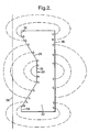
- Figure 2 shows the magnet 22 on an enlarged scale with dotted lines representing lines of magnetic flux between respective magnetic poles designated N and S on its front surface 24 and corresponding poles of opposite polarity on its surface 36 opposite to the front surface.
- the path of the Hall Effect sensor is represented by a chain-dotted line 38.
- Satisfactory results have been achieved with a magnet of overall length 11.3 mm, width (perpendicular to the plane of Figure 2) 3 mm, and maximum thickness 3.8 mm; the central zone 26 being of length 3.5 mm and having a thickness 2.1 mm, and the end zones 32 and 34 each being of length 0.4 mm.
- Such a magnet is suitable for use in a sensing system where the distance between the end zones 32, 34 and the sensing element of the Hall Effect sensor 20 is 1.25 mm.
- Sensor systems in accordance with the invention find particular application in rear view mirrors for motor vehicles of the type in which the orientation of the mirror glass is adjustable relative to the mirror housing by means of two screw jack drives arranged to adjust the orientation of the mirror glass about mutually orthogonal axes.
- a mirror assembly of this type is described in EP-A-0549173.
- a respective sensor system in accordance with the invention may be associated with each screw jack drive so as to provide an electrical signal indicating the actual position of the mirror glass.
- Such position sensor systems are required for use when such a mirror is used in conjunction with a system for storing a plurality of desired orientations for the mirror glass so that the mirror may be adjusted automatically in accordance with the requirements of a number of individual drivers.
- This invention relates to a sensor system for measuring linear displacement of a first member relative to a second member, comprising an analogue Hall Effect.sensor secured to the first member in an orientation to sense magnetic flux in a sensing direction perpendicular to said direction of relative movement, and a permanent magnet secured to the second member and having a front surface facing the Hall Effect sensor and extending along the direction of relative movement between the first and second members.
- An analogue Hall Effect sensor produces an output voltage related to the component of the flux density of a magnetic field in which it is located which is perpendicular to its sensing surface.
- the sensor produces zero output voltage when subject to a magnetic field of sufficient strength in one direction and its maximum output voltage when subject to a magnetic field of the same magnitude in the opposite direction. In the absence of a magnetic field, the sensor produces an output voltage of half its maximum voltage.
- GB-A-1109220 disclosed a sensor system of this type in which the front surface is concave in the direction of relative movement so that the magnetic flux at the Hall Effect sensor has a minimum value when the latter is positioned opposite a central location at which the concavity of the surface has maximum depth.
- a second Hall Effect sensor is mounted adjacent to the first sensor for simultaneous movement therewith. The outputs of the two sensors are combined electronically in order to determine the side of the central location on which the sensors are located.
- US-A-5 493 216 disclosed a sensor system of the type described above in which the permanent magnet is magnetised so that the front surface has a first magnetic pole of a first magnetic polarity at a first end and a second magnetic pole of a second magnetic polarity at a second end spaced from the first end in the direction of travel, and
- the front surface is concave in the direction of relative movement between the first and second members and is shaped to cause the magnetic field to vary such that the normalised vector of the flux density passing through the Hall Effect sensor varies in a substantially linear manner along the path of the Hall Effect sensor. Consequently, the output voltage of the Hall Effect sensor bears a substantially linear relation to position.
- the Hall Effect sensor is exposed to a magnetic field which changes polarity as the first and second members pass through a relative position in the centre of their range. Consequently, the sensor can be arranged to produce its full range of output voltages, thus maximising the resolution obtained.
- Figure 1 shows a linear position sensor system in accordance with the invention, comprising a hollow cylindrical housing 10 having a coupling eye 12 at one end, whereby it may be connected to one of the two members (not shown) whose relative position is to be measured.
- the housing 10 has a hole 14 at the end opposite to the coupling member 12.
- the hole 14 serves as a slide guide for a rod 16 which projects into the housing 10 and has a second coupling eye 18 on its outer end for connection of the two members whose relative position is to be sensed.
- an analogue Hall Effect sensor 20 is embedded in the inner cylindrical wall of the housing 10 about half way along its length.
- the rod 16 carries an embedded permanent magnet 22 which is positioned with a front surface 24 confronting the Hall Effect sensor 20.
- the Hall Effect sensor 20 is preferably a so-called ratiometric Hall Effect sensor in which the output is linearly proportional both to the normal component of the flux vector passing through the sensing element and to the supply voltage.
- the magnet 22 has a concavity in its front surface 24.
- the concavity has a flat central zone 26 extending parallel to the axis of the rod 16, on each end of which is a respective tapering intermediate zone 28, 30 and an end zone 32, 34 parallel to the central zone 26.
- Figure 2 shows the magnet 22 on an enlarged scale with dotted lines representing lines of magnetic flux between respective magnetic poles designated N and S on its front surface 24 and corresponding poles of opposite polarity on its surface 36 opposite to the front surface.
- the path of the Hall Effect sensor is represented by a chain-dotted line 38.
- Satisfactory results have been achieved with a magnet of overall length 11.3 mm, width (perpendicular to the plane of Figure 2) 3 mm, and maximum thickness 3.8 mm; the central zone 26 being of length 3.5 mm and having a thickness 2.1 mm, and the end zones 32 and 34 each being of length 0.4 mm.
- Such a magnet is suitable for use in a sensing system where the distance between the end zones 32, 34 and the sensing element of the Hall Effect sensor 20 is 1.25 mm.
- Sensor systems in accordance with the invention find particular application in rear view mirrors for motor vehicles of the type in which the orientation of the mirror glass is adjustable relative to the mirror housing by means of two screw jack drives arranged to adjust the orientation of the mirror glass about mutually orthogonal axes.
- a mirror assembly of this type is described in EP-A-0549173.
- a respective sensor system in accordance with the invention may be associated with each screw jack drive so as to provide an electrical signal indicating the actual position of the mirror glass.
- Such position sensor systems are required for use when such a mirror is used in conjunction with a system for storing a plurality of desired orientations for the mirror glass so that the mirror may be adjusted automatically in accordance with the requirements of a number of individual drivers.
Landscapes
- Physics & Mathematics (AREA)
- General Physics & Mathematics (AREA)
- Transmission And Conversion Of Sensor Element Output (AREA)
- Measurement Of Length, Angles, Or The Like Using Electric Or Magnetic Means (AREA)
Claims (7)
- Sensorsystem zum Messen eines linearen Versatzes eines ersten Teils (10) relativ zu einem zweiten Teil (12), mit einem analogen Hall-Effekt-Sensor, der an dem ersten Teil (10) in einer Orientierung zum Erfassen eines magnetischen Flusses in einer Erfassungsrichtung, die senkrecht zu der Richtung der relativen Bewegung ist, angebracht ist, und einem Permanentmagneten (22), der an dem zweiten Teil (12) angebracht ist und eine vordere Oberfläche, die den Hall-Effekt-Sensor anblickt und sich entlang der Richtung der relativen Bewegung zwischen dem ersten und dem zweiten Teil (10, 12) erstreckt, aufweist,
bei dem der Permanentmagnet (22) so magnetisiert ist, daß die vordere Oberfläche (24) einen ersten magnetischen Pol einer ersten magnetischen Polarität (N) an einem ersten Ende (28) und einen zweiten magnetischen Pol einer zweiten magnetischen Polarität (S) an einem zweiten Ende (30), das von dem ersten Ende in der Bewegungsrichtung getrennt ist, aufweist,
dadurch gekennzeichnet, daß die vordere Oberfläche (24) konkav ist in der Richtung der Relativbewegung zwischen dem ersten und dem zweiten Teil (10, 12) und geformt ist zum Bringen der Flußdichte zum Variieren in einer im wesentlichen linearen Weise entlang des Pfades (38) des Hall-Effekt-Sensors (20), und daß eine Oberfläche (36) des Permanentmagneten, die der vorderen Oberfläche (24) entgegengesetzt ist, einen magnetischen Pol der zweiten magnetischen Polarität (S) entgegengesetzt zu dem ersten magnetischen Pol und einen anderen magnetischen Pol der ersten magnetischen Polarität (N) entgegengesetzt zu dem zweiten magnetischen Pol aufweist. - Sensorsystem nach Anspruch 1, bei dem die vordere Oberfläche (24) eine konstante Breite in einer Richtung senkrecht zu sowohl der Richtung der Relativbewegung als auch zu der Erfassungsrichtung aufweist.
- Sensorsystem nach Anspruch 1 oder 2, bei dem die vordere Oberfläche (24) einen zentralen Abschnitt (26) aufweist, der eine plane Oberfläche senkrecht zu der magnetischen Achse des Permanentmagneten (22) aufweist.
- Sensorsystem nach Anspruch 3, bei dem die vordere Oberfläche zwei Endabschnitte (32, 34) aufweist, die plane Oberflächen senkrecht zu der magnetischen Achse aufweisen.
- Sensorsystem nach Anspruch 3 oder 4, bei dem die vordere Oberfläche (24) zwei Zwischenabschnitte (28, 30) auf entgegengesetzten Seiten des zentralen Abschnitts (24) aufweist, die mit entgegengesetzten Winkeln zu der magnetischen Achse geneigt sind.
- Sensorsystem nach Anspruch 5, bei dem die Zwischenabschnitte (28, 30) plane Oberflächen aufweisen.
Applications Claiming Priority (2)
| Application Number | Priority Date | Filing Date | Title |
|---|---|---|---|
| GB9720911 | 1997-10-03 | ||
| GBGB9720911.8A GB9720911D0 (en) | 1997-10-03 | 1997-10-03 | Hall effect sensor system |
Publications (2)
| Publication Number | Publication Date |
|---|---|
| EP0907068A1 EP0907068A1 (de) | 1999-04-07 |
| EP0907068B1 true EP0907068B1 (de) | 2004-05-26 |
Family
ID=10819939
Family Applications (1)
| Application Number | Title | Priority Date | Filing Date |
|---|---|---|---|
| EP98307998A Expired - Lifetime EP0907068B1 (de) | 1997-10-03 | 1998-10-01 | Hallsensorsystem |
Country Status (5)
| Country | Link |
|---|---|
| US (1) | US6215299B1 (de) |
| EP (1) | EP0907068B1 (de) |
| JP (1) | JPH11160010A (de) |
| DE (1) | DE69824103T2 (de) |
| GB (1) | GB9720911D0 (de) |
Cited By (5)
| Publication number | Priority date | Publication date | Assignee | Title |
|---|---|---|---|---|
| US7208943B2 (en) | 2005-06-03 | 2007-04-24 | Delphi Technologies, Inc. | Electrical device enclosure |
| US7230419B2 (en) | 2005-06-03 | 2007-06-12 | Delphi Technologies, Inc. | Rotary position sensor |
| CN107093508A (zh) * | 2016-02-18 | 2017-08-25 | 英飞凌科技股份有限公司 | 磁体装置和传感器设备 |
| US11041917B2 (en) | 2019-05-07 | 2021-06-22 | Allison Transmission, Inc. | Sensing systems with orientation selection mechanisms |
| US11268829B2 (en) | 2018-04-23 | 2022-03-08 | Corephotonics Ltd | Optical-path folding-element with an extended two degree of freedom rotation range |
Families Citing this family (123)
| Publication number | Priority date | Publication date | Assignee | Title |
|---|---|---|---|---|
| US6304078B1 (en) | 1998-12-09 | 2001-10-16 | Cts Corporation | Linear position sensor |
| US6426619B1 (en) * | 1998-12-09 | 2002-07-30 | Cts Corporation | Pedal with integrated position sensor |
| US6211668B1 (en) | 1998-12-09 | 2001-04-03 | Cts | Magnetic position sensor having opposed tapered magnets |
| DE19917466C1 (de) | 1999-04-17 | 2000-08-10 | Bosch Gmbh Robert | Wegmeßvorrichtung |
| DE19917464A1 (de) | 1999-04-17 | 2000-11-02 | Bosch Gmbh Robert | Wegmeßvorrichtung |
| FR2792765B1 (fr) * | 1999-04-23 | 2001-07-27 | Sagem | Actionneur lineaire electromagnetique a capteur de position |
| DE29913183U1 (de) * | 1999-07-28 | 1999-10-07 | Heilmeier & Weinlein Fabrik für Oel-Hydraulik GmbH & Co KG, 81673 München | Elektrischer Wegaufnehmer für ein Hydraulik-Gerät |
| JP3597733B2 (ja) * | 1999-08-09 | 2004-12-08 | アルプス電気株式会社 | 磁気式変位検出装置 |
| JP2001221653A (ja) * | 1999-12-01 | 2001-08-17 | Honda Motor Co Ltd | 変位検出装置 |
| JP2003524778A (ja) * | 2000-01-13 | 2003-08-19 | コンティネンタル・テーベス・アクチエンゲゼルシヤフト・ウント・コンパニー・オッフェネ・ハンデルスゲゼルシヤフト | 線形変位センサおよび自動車用操作装置としてその使用 |
| DE10023654A1 (de) * | 2000-05-13 | 2001-11-22 | Daimler Chrysler Ag | Positionsdetektor |
| US6867680B1 (en) * | 2000-06-30 | 2005-03-15 | Otto Controls Division, Otto Engineering, Inc | Dual magnet hall effect switch |
| JP4291936B2 (ja) * | 2000-07-12 | 2009-07-08 | カヤバ工業株式会社 | 回転角度センサ |
| US6448763B1 (en) * | 2001-01-10 | 2002-09-10 | Siemens Corporation | System for magnetization to produce linear change in field angle |
| GB0110313D0 (en) * | 2001-04-27 | 2001-06-20 | Hall Effect Technologies Ltd | Apparatus and method for analysing a fluid |
| US6823270B1 (en) | 2001-06-20 | 2004-11-23 | Curtis Roys | Fluid flow monitoring system |
| US6850849B1 (en) | 2001-06-20 | 2005-02-01 | Curtis Roys | Fluid flow monitor and control system |
| DE10244703A1 (de) * | 2001-09-27 | 2003-04-10 | Marquardt Gmbh | Einrichtung zur Messung von Wegen und/oder Positionen |
| US7034523B2 (en) | 2001-09-27 | 2006-04-25 | Marquardt Gmbh | Device for measuring paths and/or positions |
| US6586929B1 (en) * | 2001-12-14 | 2003-07-01 | Wabash Technologies, Inc. | Magnetic position sensor having shaped pole pieces for improved output linearity |
| US6798195B2 (en) * | 2001-12-14 | 2004-09-28 | Wabash Technologies, Inc. | Magnetic position sensor having shaped pole pieces at least partially formed of a non-magnetic material for producing a magnetic field having varying magnetic flux density along an axis |
| FR2836755B1 (fr) * | 2002-03-01 | 2004-08-20 | Johnson Contr Automotive Elect | Actionneur electromagnetique a force d'attraction controlee |
| US6690160B2 (en) | 2002-04-22 | 2004-02-10 | Deere & Company | Position sensing apparatus |
| DE10219807C1 (de) * | 2002-05-02 | 2003-07-17 | Bruss Dichtungstechnik | Vorrichtung zur Messung des Drehwinkels eines rotierenden Maschinenteils |
| US6731109B2 (en) | 2002-07-12 | 2004-05-04 | Wabash Technologies, Inc. | Magnetic position sensor having a stepped magnet interface |
| DE10348887A1 (de) * | 2002-10-23 | 2004-05-13 | Carl Zeiss | Tastkopf für ein Koordinatenmessgerät |
| US6921107B2 (en) * | 2002-12-11 | 2005-07-26 | Trw Inc. | Apparatus for sensing vehicle seat position |
| AU2003288653A1 (en) * | 2003-01-08 | 2004-08-10 | Koninklijke Philips Electronics N.V. | Arrangement for determining position |
| US6894485B2 (en) * | 2003-02-10 | 2005-05-17 | Delphi Technologies, Inc. | Position sensing by measuring intensity of magnetic flux passing through an aperture in a movable element |
| CN101424544B (zh) * | 2003-02-14 | 2012-04-25 | Bei传感器及系统有限公司 | 使用线性霍尔效应传感器、具有增强线性磁体配置的位置传感器 |
| JP4269961B2 (ja) * | 2003-03-31 | 2009-05-27 | 株式会社デンソー | 回転角度検出装置 |
| JP4108531B2 (ja) * | 2003-05-07 | 2008-06-25 | アルプス電気株式会社 | 部材位置検出装置 |
| US6873151B2 (en) * | 2003-07-08 | 2005-03-29 | Delphi Technologies, Inc. | Sensor assembly for sensing angular position |
| JP2005044702A (ja) * | 2003-07-25 | 2005-02-17 | Asa Denshi Kogyo Kk | 磁性体検出装置、磁気スイッチおよび移動体検出システム |
| JP4545406B2 (ja) | 2003-09-03 | 2010-09-15 | 三菱電機株式会社 | 位置検出装置 |
| US7009388B2 (en) * | 2003-12-11 | 2006-03-07 | Wabash Technologies, Inc. | Magnetic position sensor having dual electronic outputs |
| US6992478B2 (en) * | 2003-12-22 | 2006-01-31 | Cts Corporation | Combination hall effect position sensor and switch |
| US7088095B1 (en) | 2004-02-04 | 2006-08-08 | Honeywell International Inc. | Balanced magnetic linear displacement sensor |
| DE102004011591A1 (de) * | 2004-03-10 | 2005-09-29 | Robert Bosch Gmbh | Verbindungselement |
| DE102004045670B3 (de) * | 2004-09-17 | 2006-02-09 | Zf Friedrichshafen Ag | Fahrzeugniveauerfassung |
| DE102004057909A1 (de) * | 2004-11-30 | 2006-06-01 | Bourns, Inc., Riverside | Linearer Positionssensor |
| US7242183B2 (en) | 2005-02-28 | 2007-07-10 | Delphi Technologies, Inc. | Low cost linear position sensor employing one permanent magnat and one galvanomagnetic sensing element |
| JP4831813B2 (ja) | 2006-01-30 | 2011-12-07 | 株式会社村上開明堂 | 位置検出装置および自動車用ミラーの鏡面角度検出装置 |
| DE102006028785B3 (de) * | 2006-06-23 | 2007-04-12 | Audi Ag | Anordnung von Positionsgebern an einer Schaltstange |
| WO2008088267A1 (en) * | 2007-01-18 | 2008-07-24 | Jolife Ab | Driving control of a reciprocating cpr apparatus |
| DE102007009389A1 (de) * | 2007-02-20 | 2008-08-21 | Bizerba Gmbh & Co. Kg | Kraftmessvorrichtung und Verfahren zur Signalauswertung |
| JP2009168721A (ja) * | 2008-01-18 | 2009-07-30 | Nippon Thompson Co Ltd | 小型スライド装置 |
| JP2009276230A (ja) * | 2008-05-15 | 2009-11-26 | Asmo Co Ltd | ストロークセンサ、アクチュエータ及び車両用ヘッドライト装置 |
| US8058867B2 (en) * | 2008-08-18 | 2011-11-15 | Deere & Company | System for determining the position of a movable member |
| JP4606484B2 (ja) * | 2008-09-02 | 2011-01-05 | アルプス電気株式会社 | 磁石を使用した移動検出装置 |
| US8471551B2 (en) * | 2010-08-26 | 2013-06-25 | Baker Hughes Incorporated | Magnetic position monitoring system and method |
| US8941397B2 (en) * | 2010-11-09 | 2015-01-27 | Karlsruher Institut Fuer Technologie | Movement and position identification sensor |
| US8322237B2 (en) * | 2011-03-10 | 2012-12-04 | General Electric Company | Coupling for a position indication device |
| JP2015038527A (ja) * | 2011-10-28 | 2015-02-26 | ピーエス特機株式会社 | 位置検出装置 |
| US11421445B2 (en) | 2013-03-15 | 2022-08-23 | August Home, Inc. | Smart lock device with near field communication |
| US9922481B2 (en) | 2014-03-12 | 2018-03-20 | August Home, Inc. | Intelligent door lock system with third party secured access to a dwelling |
| US9528294B2 (en) | 2013-03-15 | 2016-12-27 | August Home, Inc. | Intelligent door lock system with a torque limitor |
| US9326094B2 (en) | 2013-03-15 | 2016-04-26 | August Home, Inc. | BLE/WiFi bridge with audio sensor |
| US9359794B2 (en) | 2014-03-12 | 2016-06-07 | August Home, Inc. | Method for operating an intelligent door knob |
| US10181232B2 (en) | 2013-03-15 | 2019-01-15 | August Home, Inc. | Wireless access control system and methods for intelligent door lock system |
| US11441332B2 (en) | 2013-03-15 | 2022-09-13 | August Home, Inc. | Mesh of cameras communicating with each other to follow a delivery agent within a dwelling |
| US9574372B2 (en) | 2013-03-15 | 2017-02-21 | August Home, Inc. | Intelligent door lock system that minimizes inertia applied to components |
| US11802422B2 (en) | 2013-03-15 | 2023-10-31 | August Home, Inc. | Video recording triggered by a smart lock device |
| US9706365B2 (en) | 2013-03-15 | 2017-07-11 | August Home, Inc. | BLE/WiFi bridge that detects signal strength of bluetooth LE devices at an interior of a dwelling |
| US9528296B1 (en) | 2013-03-15 | 2016-12-27 | August Home, Inc. | Off center drive mechanism for thumb turning lock system for intelligent door system |
| US9695616B2 (en) | 2013-03-15 | 2017-07-04 | August Home, Inc. | Intelligent door lock system and vibration/tapping sensing device to lock or unlock a door |
| US11352812B2 (en) | 2013-03-15 | 2022-06-07 | August Home, Inc. | Door lock system coupled to an image capture device |
| US10140828B2 (en) | 2015-06-04 | 2018-11-27 | August Home, Inc. | Intelligent door lock system with camera and motion detector |
| US10443266B2 (en) | 2013-03-15 | 2019-10-15 | August Home, Inc. | Intelligent door lock system with manual operation and push notification |
| US11043055B2 (en) | 2013-03-15 | 2021-06-22 | August Home, Inc. | Door lock system with contact sensor |
| US9704314B2 (en) | 2014-08-13 | 2017-07-11 | August Home, Inc. | BLE/WiFi bridge that detects signal strength of Bluetooth LE devices at an exterior of a dwelling |
| US10691953B2 (en) | 2013-03-15 | 2020-06-23 | August Home, Inc. | Door lock system with one or more virtual fences |
| US9447609B2 (en) | 2013-03-15 | 2016-09-20 | August Home, Inc. | Mobile device that detects tappings/vibrations which are used to lock or unlock a door |
| US11072945B2 (en) | 2013-03-15 | 2021-07-27 | August Home, Inc. | Video recording triggered by a smart lock device |
| US9818247B2 (en) | 2015-06-05 | 2017-11-14 | August Home, Inc. | Intelligent door lock system with keypad |
| US10388094B2 (en) | 2013-03-15 | 2019-08-20 | August Home Inc. | Intelligent door lock system with notification to user regarding battery status |
| US11527121B2 (en) | 2013-03-15 | 2022-12-13 | August Home, Inc. | Door lock system with contact sensor |
| US9916746B2 (en) | 2013-03-15 | 2018-03-13 | August Home, Inc. | Security system coupled to a door lock system |
| US9725927B1 (en) | 2014-03-12 | 2017-08-08 | August Home, Inc. | System for intelligent door knob (handle) |
| US9382739B1 (en) | 2013-03-15 | 2016-07-05 | August Home, Inc. | Determining right or left hand side door installation |
| WO2014199338A2 (en) | 2013-06-13 | 2014-12-18 | Corephotonics Ltd. | Dual aperture zoom digital camera |
| EP3779564B1 (de) | 2013-07-04 | 2024-04-10 | Corephotonics Ltd. | Miniatur-teleobjektivanordnung |
| CN105917641B (zh) | 2013-08-01 | 2018-10-19 | 核心光电有限公司 | 具有自动聚焦的纤薄多孔径成像系统及其使用方法 |
| US9392188B2 (en) | 2014-08-10 | 2016-07-12 | Corephotonics Ltd. | Zoom dual-aperture camera with folded lens |
| DE102014225540B4 (de) * | 2014-12-11 | 2020-03-12 | Conti Temic Microelectronic Gmbh | Magnetanordnung für einen magnetischen Wegmessgeber |
| CN112327463B (zh) | 2015-01-03 | 2022-10-14 | 核心光电有限公司 | 微型长焦镜头模块和使用该镜头模块的相机 |
| DE102015104246A1 (de) | 2015-03-20 | 2016-09-22 | Ipgate Ag | Betätigungsvorrichtung für eine Kraftfahrzeugbremse |
| WO2016166730A1 (en) | 2015-04-16 | 2016-10-20 | Corephotonics Ltd. | Auto focus and optical image stabilization in a compact folded camera |
| CN205078772U (zh) | 2015-05-04 | 2016-03-09 | 泰科电子(上海)有限公司 | 用于位置传感器的磁铁、磁铁组件以及包含磁铁组件的感测系统 |
| JP2018151159A (ja) * | 2015-08-04 | 2018-09-27 | ヤマハ発動機株式会社 | 相対位置検出装置、アクセルポジションセンサ及び車両 |
| US10230898B2 (en) | 2015-08-13 | 2019-03-12 | Corephotonics Ltd. | Dual aperture zoom camera with video support and switching / non-switching dynamic control |
| JP6647900B2 (ja) * | 2016-02-09 | 2020-02-14 | Ntn株式会社 | 電動アクチュエータ |
| JP6938114B2 (ja) * | 2016-03-28 | 2021-09-22 | 株式会社ハーマン | ガスコンロ |
| KR102002718B1 (ko) | 2016-05-30 | 2019-10-18 | 코어포토닉스 리미티드 | 회전식 볼-가이드 음성 코일 모터 |
| CN112217977A (zh) | 2016-06-19 | 2021-01-12 | 核心光电有限公司 | 双孔径摄影机系统中的帧同步 |
| CN111367039B (zh) | 2016-07-07 | 2023-02-03 | 核心光电有限公司 | 用于折叠式光学装置的线性滚珠引导音圈电动机 |
| EP3563193B1 (de) | 2016-12-28 | 2021-03-31 | Corephotonics Ltd. | Gefaltete kamerastruktur mit einem erweiterten lichtfaltelement-scanbereich |
| EP4145206A1 (de) | 2017-01-12 | 2023-03-08 | Corephotonics Ltd. | Kompakte gefaltete kamera |
| KR102770496B1 (ko) | 2017-03-15 | 2025-02-18 | 코어포토닉스 리미티드 | 파노라마 스캐닝 범위를 갖는 카메라 |
| KR102666902B1 (ko) | 2017-11-23 | 2024-05-16 | 코어포토닉스 리미티드 | 컴팩트 폴디드 카메라 구조 |
| KR102091369B1 (ko) | 2018-02-05 | 2020-05-18 | 코어포토닉스 리미티드 | 폴디드 카메라에 대한 감소된 높이 페널티 |
| WO2019155289A1 (en) | 2018-02-12 | 2019-08-15 | Corephotonics Ltd. | Folded camera with optical image stabilization |
| WO2020039302A1 (en) | 2018-08-22 | 2020-02-27 | Corephotonics Ltd. | Two-state zoom folded camera |
| CN121284176A (zh) | 2019-07-31 | 2026-01-06 | 核心光电有限公司 | 在相机摇摄或运动中创建背景模糊的系统 |
| CN119179194A (zh) | 2019-12-03 | 2024-12-24 | 核心光电有限公司 | 致动器 |
| US11949976B2 (en) | 2019-12-09 | 2024-04-02 | Corephotonics Ltd. | Systems and methods for obtaining a smart panoramic image |
| CN114641805A (zh) | 2020-02-22 | 2022-06-17 | 核心光电有限公司 | 用于微距摄影的分屏特征 |
| KR20250052463A (ko) | 2020-04-26 | 2025-04-18 | 코어포토닉스 리미티드 | 홀 바 센서 보정을 위한 온도 제어 |
| KR102495627B1 (ko) | 2020-05-17 | 2023-02-06 | 코어포토닉스 리미티드 | 전체 시야 레퍼런스 이미지 존재 하의 이미지 스티칭 |
| KR102875017B1 (ko) | 2020-05-30 | 2025-10-21 | 코어포토닉스 리미티드 | 슈퍼 매크로 이미지를 얻기 위한 시스템 및 방법 |
| US11637977B2 (en) | 2020-07-15 | 2023-04-25 | Corephotonics Ltd. | Image sensors and sensing methods to obtain time-of-flight and phase detection information |
| CN119583939A (zh) | 2020-07-15 | 2025-03-07 | 核心光电有限公司 | 移动电子装置 |
| CN118433505A (zh) | 2020-07-31 | 2024-08-02 | 核心光电有限公司 | 相机 |
| CN114424104B (zh) | 2020-08-12 | 2023-06-30 | 核心光电有限公司 | 扫描折叠相机中的光学防抖 |
| KR20230087449A (ko) | 2020-09-17 | 2023-06-16 | 아싸 아블로이 인코퍼레이티드 | 로크 위치를 위한 자기 센서 |
| DE102020211660B4 (de) * | 2020-09-17 | 2023-03-30 | Festo Se & Co. Kg | Stellvorrichtung zum Bereitstellen einer Stellbewegung |
| AU2021347522A1 (en) | 2020-09-25 | 2023-04-27 | Assa Abloy Australia Pty Limited | Door lock with magnetometers |
| KR20230091860A (ko) | 2020-09-25 | 2023-06-23 | 아싸 아블로이 오스트레일리아 피티와이 리미티드 | 다중 배향 도어 로크 |
| TWI836372B (zh) | 2021-03-11 | 2024-03-21 | 以色列商核心光電有限公司 | 彈出式照相機系統 |
| US12007671B2 (en) | 2021-06-08 | 2024-06-11 | Corephotonics Ltd. | Systems and cameras for tilting a focal plane of a super-macro image |
| EP4256401A4 (de) | 2021-07-21 | 2024-07-10 | Corephotonics Ltd. | Ausklappbare mobile kameras und aktuatoren |
| CN121091576A (zh) | 2022-03-24 | 2025-12-09 | 核心光电有限公司 | 薄型紧凑透镜光学图像稳定 |
| US12212257B2 (en) | 2023-03-08 | 2025-01-28 | Raytheon Company | Permanent magnet synchronous motor (PMSM) integrated position sensing |
Citations (1)
| Publication number | Priority date | Publication date | Assignee | Title |
|---|---|---|---|---|
| EP1002218A1 (de) * | 1997-08-06 | 2000-05-24 | Fisher Controls International, Inc. | Magnetischer wegsensor mit flussleitender polstruktur |
Family Cites Families (7)
| Publication number | Priority date | Publication date | Assignee | Title |
|---|---|---|---|---|
| FR1339956A (fr) * | 1962-11-27 | 1963-10-11 | Gen Precision Inc | Dispositif de conversion à effet hall |
| US3419798A (en) * | 1965-12-17 | 1968-12-31 | Clark Equipment Co | Displacement sensing transducer using hall effect devices |
| US4107604A (en) | 1976-12-01 | 1978-08-15 | Compunetics, Incorporated | Hall effect displacement transducer using a bar magnet parallel to the plane of the Hall device |
| US4268814A (en) * | 1978-10-26 | 1981-05-19 | Texas Instruments Incorporated | Solid state keyboard |
| US5159268A (en) * | 1991-02-21 | 1992-10-27 | Honeywell Inc. | Rotational position sensor with a Hall effect device and shaped magnet |
| US5493216A (en) * | 1993-09-08 | 1996-02-20 | Asa Electronic Industry Co., Ltd. | Magnetic position detector |
| US5955881A (en) * | 1994-10-18 | 1999-09-21 | Cts Corporation | Linkage position sensor having a magnet with two ramped sections for providing variable magnetic field |
-
1997
- 1997-10-03 GB GBGB9720911.8A patent/GB9720911D0/en not_active Ceased
-
1998
- 1998-10-01 DE DE69824103T patent/DE69824103T2/de not_active Expired - Fee Related
- 1998-10-01 EP EP98307998A patent/EP0907068B1/de not_active Expired - Lifetime
- 1998-10-02 JP JP10280754A patent/JPH11160010A/ja active Pending
- 1998-10-05 US US09/166,361 patent/US6215299B1/en not_active Expired - Lifetime
Patent Citations (1)
| Publication number | Priority date | Publication date | Assignee | Title |
|---|---|---|---|---|
| EP1002218A1 (de) * | 1997-08-06 | 2000-05-24 | Fisher Controls International, Inc. | Magnetischer wegsensor mit flussleitender polstruktur |
Cited By (7)
| Publication number | Priority date | Publication date | Assignee | Title |
|---|---|---|---|---|
| US7208943B2 (en) | 2005-06-03 | 2007-04-24 | Delphi Technologies, Inc. | Electrical device enclosure |
| US7230419B2 (en) | 2005-06-03 | 2007-06-12 | Delphi Technologies, Inc. | Rotary position sensor |
| CN107093508A (zh) * | 2016-02-18 | 2017-08-25 | 英飞凌科技股份有限公司 | 磁体装置和传感器设备 |
| CN107093508B (zh) * | 2016-02-18 | 2020-02-28 | 英飞凌科技股份有限公司 | 磁体装置和传感器设备 |
| US11268829B2 (en) | 2018-04-23 | 2022-03-08 | Corephotonics Ltd | Optical-path folding-element with an extended two degree of freedom rotation range |
| US11359937B2 (en) | 2018-04-23 | 2022-06-14 | Corephotonics Ltd. | Optical-path folding-element with an extended two degree of freedom rotation range |
| US11041917B2 (en) | 2019-05-07 | 2021-06-22 | Allison Transmission, Inc. | Sensing systems with orientation selection mechanisms |
Also Published As
| Publication number | Publication date |
|---|---|
| US6215299B1 (en) | 2001-04-10 |
| GB9720911D0 (en) | 1997-12-03 |
| JPH11160010A (ja) | 1999-06-18 |
| DE69824103D1 (de) | 2004-07-01 |
| DE69824103T2 (de) | 2005-06-30 |
| EP0907068A1 (de) | 1999-04-07 |
Similar Documents
| Publication | Publication Date | Title |
|---|---|---|
| EP0907068B1 (de) | Hallsensorsystem | |
| US4821218A (en) | Method and apparatus for determining at least one characteristic value of movement of a body | |
| US6812694B2 (en) | Magnetic sensor adjusting method, magnetic sensor adjusting device and magnetic sensor | |
| US4574625A (en) | Surface finish, displacement and contour scanner | |
| EP0427882A1 (de) | Vorrichtung zur Messung von kleinen Verschiebungen | |
| EP0521114B1 (de) | Langhubiger multi-magnet positionsmessfühler | |
| EP0561524B1 (de) | Bewegungswandler | |
| EP0707195B1 (de) | Magnetischer Detektor der Bewegung eines Gegenstands | |
| CA2422673A1 (en) | Position sensing apparatus | |
| JP2003519372A (ja) | 磁気抵抗位置検出装置 | |
| US7284337B2 (en) | Probe head for a coordinate measuring machine | |
| WO1999008073A1 (en) | Flux shaping pole pieces for a magnetic displacement sensor | |
| EP0484250B1 (de) | Apparat zur Bestimmung der Position einer beweglichen Linse im Objektivtubus einer Kamera | |
| US5475600A (en) | Mobile robot which utilizes inertial navigation to calculate shortest return distance | |
| EP1365208A1 (de) | Verschiebungssensor | |
| US5813124A (en) | Angle measuring device | |
| US20230013016A1 (en) | Valve having a position sensing means | |
| US7868490B2 (en) | Actuator | |
| JP3311429B2 (ja) | 基準位置検出装置 | |
| US6480008B2 (en) | Capacitive distance sensor for surface configuration determining apparatus | |
| US7026809B2 (en) | Magnetic sensor for detecting position and/or speed of a mobile target | |
| EP0459066B1 (de) | Positionsgeregelte Elektromagnetische Vorrichtung | |
| US6141881A (en) | Electronic analogue compass | |
| JP3335738B2 (ja) | 磁気式位置センサ | |
| JPH074905A (ja) | 移動量検出器 |
Legal Events
| Date | Code | Title | Description |
|---|---|---|---|
| PUAI | Public reference made under article 153(3) epc to a published international application that has entered the european phase |
Free format text: ORIGINAL CODE: 0009012 |
|
| AK | Designated contracting states |
Kind code of ref document: A1 Designated state(s): DE ES FR GB IT NL SE |
|
| AX | Request for extension of the european patent |
Free format text: AL;LT;LV;MK;RO;SI |
|
| 17P | Request for examination filed |
Effective date: 19990906 |
|
| AKX | Designation fees paid |
Free format text: DE ES FR GB IT NL SE |
|
| RAP1 | Party data changed (applicant data changed or rights of an application transferred) |
Owner name: SCHEFENACKER VISION SYSTEMS AUSTRALIA PTY LTD |
|
| 17Q | First examination report despatched |
Effective date: 20020918 |
|
| GRAH | Despatch of communication of intention to grant a patent |
Free format text: ORIGINAL CODE: EPIDOS IGRA |
|
| GRAS | Grant fee paid |
Free format text: ORIGINAL CODE: EPIDOSNIGR3 |
|
| GRAA | (expected) grant |
Free format text: ORIGINAL CODE: 0009210 |
|
| AK | Designated contracting states |
Kind code of ref document: B1 Designated state(s): DE ES FR GB IT NL SE |
|
| PG25 | Lapsed in a contracting state [announced via postgrant information from national office to epo] |
Ref country code: NL Free format text: LAPSE BECAUSE OF FAILURE TO SUBMIT A TRANSLATION OF THE DESCRIPTION OR TO PAY THE FEE WITHIN THE PRESCRIBED TIME-LIMIT Effective date: 20040526 Ref country code: IT Free format text: LAPSE BECAUSE OF FAILURE TO SUBMIT A TRANSLATION OF THE DESCRIPTION OR TO PAY THE FEE WITHIN THE PRESCRIBED TIME-LIMIT;WARNING: LAPSES OF ITALIAN PATENTS WITH EFFECTIVE DATE BEFORE 2007 MAY HAVE OCCURRED AT ANY TIME BEFORE 2007. THE CORRECT EFFECTIVE DATE MAY BE DIFFERENT FROM THE ONE RECORDED. Effective date: 20040526 |
|
| REG | Reference to a national code |
Ref country code: GB Ref legal event code: FG4D |
|
| REF | Corresponds to: |
Ref document number: 69824103 Country of ref document: DE Date of ref document: 20040701 Kind code of ref document: P |
|
| PG25 | Lapsed in a contracting state [announced via postgrant information from national office to epo] |
Ref country code: SE Free format text: LAPSE BECAUSE OF FAILURE TO SUBMIT A TRANSLATION OF THE DESCRIPTION OR TO PAY THE FEE WITHIN THE PRESCRIBED TIME-LIMIT Effective date: 20040826 |
|
| PG25 | Lapsed in a contracting state [announced via postgrant information from national office to epo] |
Ref country code: ES Free format text: LAPSE BECAUSE OF FAILURE TO SUBMIT A TRANSLATION OF THE DESCRIPTION OR TO PAY THE FEE WITHIN THE PRESCRIBED TIME-LIMIT Effective date: 20040906 |
|
| NLV1 | Nl: lapsed or annulled due to failure to fulfill the requirements of art. 29p and 29m of the patents act | ||
| ET | Fr: translation filed | ||
| PLBE | No opposition filed within time limit |
Free format text: ORIGINAL CODE: 0009261 |
|
| STAA | Information on the status of an ep patent application or granted ep patent |
Free format text: STATUS: NO OPPOSITION FILED WITHIN TIME LIMIT |
|
| PG25 | Lapsed in a contracting state [announced via postgrant information from national office to epo] |
Ref country code: DE Free format text: LAPSE BECAUSE OF NON-PAYMENT OF DUE FEES Effective date: 20050503 |
|
| 26N | No opposition filed |
Effective date: 20050301 |
|
| REG | Reference to a national code |
Ref country code: GB Ref legal event code: 732E |
|
| REG | Reference to a national code |
Ref country code: FR Ref legal event code: TP Ref country code: FR Ref legal event code: CD Ref country code: FR Ref legal event code: CA |
|
| REG | Reference to a national code |
Ref country code: FR Ref legal event code: PLFP Year of fee payment: 18 |
|
| REG | Reference to a national code |
Ref country code: FR Ref legal event code: PLFP Year of fee payment: 19 |
|
| REG | Reference to a national code |
Ref country code: FR Ref legal event code: PLFP Year of fee payment: 20 |
|
| PGFP | Annual fee paid to national office [announced via postgrant information from national office to epo] |
Ref country code: FR Payment date: 20171024 Year of fee payment: 20 |
|
| PGFP | Annual fee paid to national office [announced via postgrant information from national office to epo] |
Ref country code: GB Payment date: 20171019 Year of fee payment: 20 |
|
| REG | Reference to a national code |
Ref country code: GB Ref legal event code: PE20 Expiry date: 20180930 |
|
| PG25 | Lapsed in a contracting state [announced via postgrant information from national office to epo] |
Ref country code: GB Free format text: LAPSE BECAUSE OF EXPIRATION OF PROTECTION Effective date: 20180930 |