EP0907046B1 - Verbesserte Ventilanordnung für Heizsysteme und Wasserheizgeräte - Google Patents
Verbesserte Ventilanordnung für Heizsysteme und Wasserheizgeräte Download PDFInfo
- Publication number
- EP0907046B1 EP0907046B1 EP19970830488 EP97830488A EP0907046B1 EP 0907046 B1 EP0907046 B1 EP 0907046B1 EP 19970830488 EP19970830488 EP 19970830488 EP 97830488 A EP97830488 A EP 97830488A EP 0907046 B1 EP0907046 B1 EP 0907046B1
- Authority
- EP
- European Patent Office
- Prior art keywords
- shutter
- valve assembly
- fluid
- valve
- fluid outlet
- Prior art date
- Legal status (The legal status is an assumption and is not a legal conclusion. Google has not performed a legal analysis and makes no representation as to the accuracy of the status listed.)
- Expired - Lifetime
Links
Images


Classifications
-
- F—MECHANICAL ENGINEERING; LIGHTING; HEATING; WEAPONS; BLASTING
- F16—ENGINEERING ELEMENTS AND UNITS; GENERAL MEASURES FOR PRODUCING AND MAINTAINING EFFECTIVE FUNCTIONING OF MACHINES OR INSTALLATIONS; THERMAL INSULATION IN GENERAL
- F16K—VALVES; TAPS; COCKS; ACTUATING-FLOATS; DEVICES FOR VENTING OR AERATING
- F16K3/00—Gate valves or sliding valves, i.e. cut-off apparatus with closing members having a sliding movement along the seat for opening and closing
- F16K3/22—Gate valves or sliding valves, i.e. cut-off apparatus with closing members having a sliding movement along the seat for opening and closing with sealing faces shaped as surfaces of solids of revolution
- F16K3/24—Gate valves or sliding valves, i.e. cut-off apparatus with closing members having a sliding movement along the seat for opening and closing with sealing faces shaped as surfaces of solids of revolution with cylindrical valve members
- F16K3/243—Packings
-
- F—MECHANICAL ENGINEERING; LIGHTING; HEATING; WEAPONS; BLASTING
- F16—ENGINEERING ELEMENTS AND UNITS; GENERAL MEASURES FOR PRODUCING AND MAINTAINING EFFECTIVE FUNCTIONING OF MACHINES OR INSTALLATIONS; THERMAL INSULATION IN GENERAL
- F16K—VALVES; TAPS; COCKS; ACTUATING-FLOATS; DEVICES FOR VENTING OR AERATING
- F16K11/00—Multiple-way valves, e.g. mixing valves; Pipe fittings incorporating such valves
- F16K11/02—Multiple-way valves, e.g. mixing valves; Pipe fittings incorporating such valves with all movable sealing faces moving as one unit
- F16K11/04—Multiple-way valves, e.g. mixing valves; Pipe fittings incorporating such valves with all movable sealing faces moving as one unit comprising only lift valves
- F16K11/044—Multiple-way valves, e.g. mixing valves; Pipe fittings incorporating such valves with all movable sealing faces moving as one unit comprising only lift valves with movable valve members positioned between valve seats
-
- F—MECHANICAL ENGINEERING; LIGHTING; HEATING; WEAPONS; BLASTING
- F16—ENGINEERING ELEMENTS AND UNITS; GENERAL MEASURES FOR PRODUCING AND MAINTAINING EFFECTIVE FUNCTIONING OF MACHINES OR INSTALLATIONS; THERMAL INSULATION IN GENERAL
- F16K—VALVES; TAPS; COCKS; ACTUATING-FLOATS; DEVICES FOR VENTING OR AERATING
- F16K11/00—Multiple-way valves, e.g. mixing valves; Pipe fittings incorporating such valves
- F16K11/02—Multiple-way valves, e.g. mixing valves; Pipe fittings incorporating such valves with all movable sealing faces moving as one unit
- F16K11/04—Multiple-way valves, e.g. mixing valves; Pipe fittings incorporating such valves with all movable sealing faces moving as one unit comprising only lift valves
- F16K11/056—Multiple-way valves, e.g. mixing valves; Pipe fittings incorporating such valves with all movable sealing faces moving as one unit comprising only lift valves with ball-shaped valve members
Definitions
- the present invention relates to a valve assembly of the type comprising the features of the preamble of claim 1.
- valve assembly of the invention is preferably, though not exclusively, intended for use in domestic heating systems and water-heating apparatuses, such as for example boilers of the so-called combined type.
- the expression 'boiler of the combined type' is used to indicate a boiler adapted to generate hot water for both space heating, or primary water, as well as hot water for sanitary use.
- valve assemblies capable of cutting off (two-way valves) or diverting (three-way valves) the fluid flowing through the circuits provided therein.
- valve assemblies should provide, on one side, the lowest pressure drop, and on the other side, the absence of leakouts from the circuit which is isolated independently of the differential pressure existing upstream and downstream the valve assembly and independently of the fluid used.
- a first known group of valve assemblies comprises a spherical or cylindrical shutter which is driven between opposite positions to respectively open and close one or two valve seats.
- valve assemblies allow, on one side, to achieve a relatively low pressure drop, on the other side they have no self-cleaning capability, that is, they are unable to dislodge the solid residues that frequently remains trapped between the shutter and its valve seat.
- valve assemblies try to ensure the required absence of leakouts by adopting a shutter made of an elastically deformable material and applying thereon a compressive force capable to deform the material within predetermined limits so as to ensure the required fluid-tight seal.
- Another drawback of the aforesaid valves of known type is related to the high energy consumption due to the fact that, in order to provide a tight closure during the valve operation, the shutter must be held against the respective seat by a compressive force continuously applied by an electric motor included in the shutter driving means.
- This motor is particularly expensive, since it should be kept in an excited state while the shutter is held against its seat, in order to ensure that the desired compressive force is exerted so as to ensure the desired service.
- a second group of valves of known type comprises a hollow cylindrical shutter, wherethrough the fluid can axially flow, which is drivingly displaceable between opposite positions to open and close, respectively, one or more fluid outlet conduits by means of its lateral side walls.
- valve assemblies while enabling on the one hand to remove any solid residue from the free end of the fluid outlet conduit and to have a relatively high (generally up to about 4 bar) differential pressure upstream and downstream of the valve, they involve on the other hand a relatively high pressure drop thus requiring the installation of expensive circulation pumps of adequate power in the circuit.
- the technical problem underlying the present invention is that of providing a valve assembly which allows to ensure, on the one side, the lowest possible pressure drop and, on the other side, the absence of leakouts from the isolated circuit, while overcoming at the same time the drawbacks indicated with regard to the aforementioned prior art.
- the term 'fluid' will be used to indicate any substance in liquid or gaseous form flowing through the valve assembly.
- the fluid referred to hereinafter is water.
- the shutter comprises an essentially cylindrical metal body laterally provided with an annular gasket, essentially made of an elastically deformable material, which is removably mounted in a respective receiving seat radially formed in the side wall of said body.
- the shutter can be received with the required interference to ensure the required fluid-tight seal which takes place between the side walls of the shutter and the corresponding valve seat in a substantially radial direction, that is, along a direction perpendicular to the travel direction of the shutter.
- valve assembly of the invention allows to use a shutter which is shaped not only for allowing an on/off type of operation, but also for a modulating operation, that is the valve is capable of regulating the flow rate of the fluid leaving the valve assembly.
- the shape of the shutter may be freely selected, if desired, so as to have the most suitable profile for providing an optimum regulation of the flow rate according to the shutter position with respect to the free end(s) of the fluid outlet conduit(s).
- At least a portion of the side wall of the shutter body may be substantially frusto-conical or curvilinear (parabolic or spherical), according to the kind of regulation sought.
- the shutter further includes an additional annular gasket, essentially made of an elastically deformable material, removably mounted in a respective receiving seat axially formed on the top face of its body.
- an additional annular gasket essentially made of an elastically deformable material, removably mounted in a respective receiving seat axially formed on the top face of its body.
- this second gasket constitutes appropriate shock-absorber means for dampening possible travel end shocks of the shutter.
- the shutter may be substantially spherical in shape, the term 'spherical' being used here to define both a fully spherical shutter body and a shutter having one or more faces which are at least partially rectilinear, provided that it also has at least one frusto-conical or curvilinear sealing surface.
- the shutter is in this case made of an elastically deformable material suitably obtainable at low cost in large-scale production by conventional moulding processes.
- differential pressures between upstream and downstream of the valve assembly up to about 4-5 bar can be provided, even with a shutter made entirely of an elastomeric material.
- the elastically deformable material used for making the aforementioned gaskets, or alternatively the shutter body is selected from the group comprising: acrylonitrile rubber (NBR), polychloroprene rubber (CR), fluorinated rubber (FP), and ethylene-propylene-diene terpolymers (EPDM).
- NBR acrylonitrile rubber
- CR polychloroprene rubber
- FP fluorinated rubber
- EPDM ethylene-propylene-diene terpolymers
- the sliding seat of the shutter is substantially cylindrical and includes at least a portion having substantially the same diameter as the largest diameter of the shutter as measured at the annular lateral gaskets, when the same are provided.
- the sliding seat is effective to guide the shutter translation movements along the required rectilinear travel path, without involving any costly precision machining.
- the first valve seat of the shutter formed upstream of the fluid outlet conduit is provided with a opening having at least one flaring bottom edge.
- the top edge of the opening of the first valve seat is also suitably flared.
- the flaring angle (meaning with this term the angle formed by the edge with a vertical line passing therethrough) is of 15° to 40° and, even more preferably, equal to about 30°.
- the valve assembly of this invention may be a two-way or a three-way valve.
- the shutter is driven by its actuator means toward and away from a single fluid outlet conduit, which is opened and closed thereby to cut off the single flowpath defined within the valve body.
- the shutter opens and, respectively, closes a pair of fluid outlet conduits alternately directing the fluid to one or the other of two flowpaths defined within the valve body.
- the end portion of the shutter sliding seat defining said second valve seat is preferably formed upstream of a second fluid outlet conduit.
- the shutter driving means comprises a linear actuator means arranged to act on a stem attached to the shutter and operated by an electric motor.
- such means is mechanically simpler and less expensive than the actuator means employed in the valves of the prior art.
- Simpler engineering also advantageously involves reduced risks of failures.
- the linear actuator means comprises a shaft having at least one threaded portion the thread pitch of which is irreversible.
- the shutter can advantageously be kept in the respective valve seat without having to keep the motor in an excited state. This allows to use a simpler and less expensive motor and to reduce the energy consumption.
- a modulating valve that is a valve capable of regulating the flow rate of the fluid leaving the valve assembly, can be produced at a very low cost.
- valve assembly of this invention further includes a plug mounted on the valve body in a fluid-tight manner and guiding the sliding movement of the shutter stem therethrough.
- the plug is adapted to seal off the shutter driving means, which is therefore structurally separated from the water circuit.
- the electrical or mechanical portions of such means can be serviced without opening the valve, that is without the system having to be drained empty.
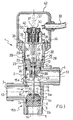
- valve assembly 1 is a three-way valve intended for installation on household water-heating apparatuses, such as for example household gas-fired boilers.
- the valve assembly 1 essentially comprises a valve body 2 in which a fluid inlet conduit 3, a first fluid outlet conduit 4, and a second fluid outlet conduit 5 are formed.
- a fluid inlet opening 12 is provided at the free end of the fluid inlet conduit 3, while a first 13 and a second 14 fluid outlet openings are formed downstream of the fluid outlet conduits 4 and 5, respectively.
- An essentially cylindrical central chamber 6 comprising two successive portions, respectively a proximal portion 6a and a distal portion 6b with respect to the fluid outlet conduit 4, having a different diameter and a predetermined length, is formed in the valve body 2 between the fluid inlet conduit 3 and the fluid outlet conduits 4, 5.
- the successive portions 6a, 6b of the central chamber 6 are connected by a flared section 6c of limited length.
- valve body 2 inside the valve body 2 are defined:
- the fluid inlet and outlet conduits 3, 4 and 5 are externally threaded for threadably coupling to the ends of threaded fittings (not shown) of respective water circuits, also not shown.
- a shutter 7 is slidably guided within the central chamber 6 for reciprocation along a substantially rectilinear travel path between a first and a second position where it closes and, respectively, opens the fluid outlet conduits 4, 5.
- the shutter 7 is guided in a substantial mating engagement within the large diameter portion 6a of the central chamber 6, while it is removably received with an interference fit, as explained hereinafter, within the portion 6b having a smaller diameter thereof.
- the central chamber 6 will be referred to hereinafter as: shutter sliding seat.
- the shutter 7 comprises an essentially cylindrical metal body 7a laterally provided with an annular gasket 8, which is essentially made of an elastically deformable material, removably mounted in a respective receiving seat 9 radially formed in the side wall of the body 7a.
- the diameter of the sliding seat 6 of the shutter 7 is substantially the same as the largest diameter of the same shutter, as measured at the annular side gasket 8.
- the sliding seat 6 is capable of effectively guiding the translation movements of the shutter 7 to ensure the required rectilinear travel thereof even without any expensive precision machining.
- the side wall of the body 7a is connected to the opposite top and bottom faces of the shutter 7 by respective substantially curvilinear portions (having here a parabolic profile) such that the flow rate of the fluid flowing through the valve assembly 1 can advantageously be regulated, as explained hereinafter.
- the shutter 7 further comprises an additional annular gasket 10, also essentially made of an elastically deformable material, removably mounted in a respective receiving seat 11 axially formed on the top face of the body 7a.
- an additional annular gasket 10 also essentially made of an elastically deformable material, removably mounted in a respective receiving seat 11 axially formed on the top face of the body 7a.
- the gasket 10 constitutes a suitable shock-absorber means to dampen any shocks to the shutter 7 at its travel end.
- the elastically deformable material constituting the aforesaid gaskets 8 and 10 is acrylonitrile rubber (NBR).
- the shutter 7 is removably received in fluid-tight manner - - at said first and second positions where it closes and, respectively, opens the fluid outlet conduits 4, 5 -- in a first and a second valve seat formed in the valve body 2 upstream of such conduits.
- the first valve seat of the shutter 7 is essentially constituted by a chamber 43 axially formed upstream of the fluid outlet conduit 4 and provided with an opening 16 adapted to place the sliding seat 6 of the shutter 7 in fluid communication with said conduit.
- the second valve sealing seat of the shutter 7 is essentially constituted by the small-diameter portion 6b of the central chamber 6 distal from the fluid outlet conduit 4.
- both said valve seats of the shutter 7 are substantially located outside of the flowpaths 15b and, respectively, 15a.
- first and second valve seats respectively.
- the shutter 7 can be received with the interference necessary to ensure the required fluid-tight fit, which will occur in a substantially radial direction, that is, perpendicularly to the travel direction of the shutter.
- the opening 16 of the first valve seat 43 is provided with opposite flaring edges forming with a vertical line a flaring angle ⁇ preferably equal to about 30°.
- the shutter 7 is attached, in a conventional way nor shown, to an end of a stem 17 which is guided for sliding movement inside a corresponding bore 18 axially formed through a plug 19 mounted in a fluid-tight manner on a cylindrical tubular portion 20 integrally formed with the valve body 2.
- the plug 19 is received in a bore 21 axially formed in the cylindrical tubular portion 20, and is provided with a flange 22 adapted to cooperate in abutting relationship with an annular detent surface 23 internally formed within the bore 21.
- An annular gasket 24 is interposed between the plug 19 and the valve body 2.
- the plug 19 For easier sliding of the stem 17, the plug 19 includes a bush 25 of a suitable anti-friction material which is received in a respective annular seat coaxially formed within the bore 18.
- Another pair of annular gaskets 26, mounted adjacent to the bush 25, ensures the necessary seal with the stem 17 so as to prevent undesired fluid leakouts.
- a ring 27 is mounted in a respective annular seat 28 internally formed in the bore 21.
- the cylindrical tubular portion 20 is provided with a plurality of radial holes 29 circumferentially arranged and equally spaced from one another, adapted to drain the cylindrical tubular portion 20 of any fluid that may have leaked through the plug 19.
- the valve assembly 1 further comprises means 30 for driving the shutter 7 along the sliding seat 6, arranged to act on a spherical tailpiece 31 formed at the free end of the stem 17.
- the driving means 30 is mounted in the cylindrical tubular portion 20, and comprises an electric motor 32, conventionally powered by means of an electric supply cable 33, which acts on a linear actuator means 34.
- the electric motor 32 is mounted on a baseplate 35 attached to the free end of the cylindrical tubular portion 20 by conventional fasteners 36 (e.g., screws).
- the linear actuator means 34 comprises in turn a shaft 37 having a threaded portion in threaded engagement with an internally threaded metal core 38 located within the windings 39 of the electric motor 32 and rotated thereby. This rotation is guided by a roll bearing 40 mounted at the top of the motor 32.
- the threaded portion of the shaft 37 is provided with an irreversible pitch thread.
- the shaft 37 is provided, at its lower end, with a fork head 41 adapted to removably receive the spherical tailpiece 31 of the stem 17, so that the stem 17 can be removably associated to the linear actuator means 34.
- the coupling between the stem 17 and the linear actuator means 34 is of reversible type: in fact, for releasing the stem 17 from the fork head 41, it is sufficient to laterally pull the spherical tailpiece 31.
- the electric motor 32 and threaded portion of the shaft 37 protruding out of the cylindrical tubular portion 20 are advantageously protected by a box-type cover 42 snap-fitted onto the cylindrical tubular portion 20.
- valve assembly 1 allows to selectively deliver the fluid to the water circuits associated to the first and second flowpaths 15a, 15b.
- the shutter 7 is positioned with interference within the second valve seat 6b so as to cut off the fluid outlet conduit 5 (see Figure 1).
- the shutter 7 is substantially received for one half into the second valve seat 6b, and the annular gasket 8 is partially compressed by the side walls of the same so as to provide the desired fluid-tight seal.
- the incoming fluid to the valve assembly 1 through the fluid inlet opening 12 will then flow along the first flowpath 15a and through the outlet opening 13 to the first water circuit associated therewith.
- the position of the shutter 7 substantially outside of the first flowpath 15a contributes to keep at a very low value the pressure drops which the fluid undergoes while flowing through the valve assembly 1.
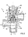
- the shutter 7 To deliver the fluid to the water circuit associated to the flowpath 15b, the shutter 7 must be shifted to a second operating position, such as that shown in Figure 2.
- the shutter 7 In moving from the first to the second operating position, the shutter 7 travels along a substantially rectilinear path within its guiding and sliding seat 6.
- the displacement of the shutter 7 is produced by exciting the windings 39 of the electric motor 32 with a supply current.
- This excitation current generates a magnetic field which rotates the metal core 38, which induces in turn a translation movement of the shaft 37 the threaded portion of which is thread-engaged with the core. This results in a vertical translation movement of the stem 17 associated to the shutter 7.
- the flow rate of the fluid flowing along the flowpath 15a can be regulated from the maximum value down to a null value through a full range of intermediate values, thanks to the shape of the joining section between the side wall of the body 7a of the shutter 7 and the top face thereof.
- the shutter 7 is substantially received for one half into the first valve seat 43 and completely closes the opening 16 wherein it is received with interference, thereby cutting off the flowpath 15a.
- the annular gasket 8 is partially compressed by the inner walls of the opening 16 and thus ensures the desired fluid-tight seal.
- the positioning of the shutter 7 substantially outside of the second flowpath 15b contributes to keep down to a very low value the pressure drops which the fluid undergoes while flowing through the valve assembly 1.
- the shutter 7 To deliver again the fluid to the water circuit associated to the flowpath 15a, the shutter 7 must be shifted for bringing the same to its first operating position shown in Figure 1.
- the flow rate of the fluid flowing along the flowpath 15b can be regulated from the maximum value down to a null value through a full range of intermediate values, thanks to the shape of the joining section between the side wall of the body 7a of the shutter 7 and the bottom face thereof.
- the threaded shaft 37 having an irreversible thread pitch advantageously allows to maintain the shutter 7 in the first or the second valve seats 43, 6b, without the electric motor 32 having to be kept in an excited state.
- Figures 3 and 4 show another embodiment of the invention, specifically a two-way valve 101 intended for installation on household water-heating apparatuses, such as for example gas-fired boilers of the combined type.
- valve 101 which are structurally or functionally equivalent to those previously described in relation to the three-way valve 1 shown in Figures 1 and 2 are indicated by the same reference numerals and will be not further described.
- Said sliding seat 6 is substantially cylindrical, has a constant diameter substantially equal to the largest diameter of the shutter 7, and is closed so as to form a receiving seat for the shutter 7, at an end portion 6d thereof distal from the fluid outlet conduit 4.
- the body 7a of the shutter 7 is essentially cylindrical and comprises a side wall connected to its top face by means of a substantially curvilinear (specifically, parabolic in profile) portion, so as to carry out an advantageous regulation of the flow rate of the fluid flowing through the valve assembly 1.
- the operation of the two-way valve assembly 101 allows the flow rate of the fluid flowing along the flowpath 15a to be regulated from the maximum value to a null value through a full range of intermediate values, by operating the shutter 7 by means of a linear actuator means 34 in the same manner as previously explained.
- the position of the shutter 7 in the seat 6d substantially outside of the flowpath 15a advantageously contributes to keep down to a very low value the pressure drops which the fluid undergoes while flowing through the valve assembly 101.
- valve assembly of this invention can be readily appreciated in the light of the foregoing description.
- a first important advantage is represented by the fact that the rectilinear movement of the shutter within its guiding and sliding seat allows to use simpler and less expensive driving means than those used in conventional known valves, thereby simplifying the valve construction as a whole and drastically cutting down manufacturing costs.
- the partial introduction of the shutter into its valve seats while providing an adequately fluid-tight seal and assuring low pressure drops, additionally allows to remove any solid particles caught at the free end of said valve seats, thereby ensuring a suitable cleaning action of the flowpaths.
- the shutter moreover, can be held in its respective valve seat without the motor having to be kept in an excited state. This allows a simpler and less expensive motor to be used and power consumption reduced.
- the shutter driving means is structurally separated from the flowpath(s), so that the electrical or mechanical portion of such means can be serviced without opening the valve, that is, without emptying the water circuit to which the same is incorporated.
Landscapes
- Engineering & Computer Science (AREA)
- General Engineering & Computer Science (AREA)
- Mechanical Engineering (AREA)
- Lift Valve (AREA)
- Multiple-Way Valves (AREA)
Claims (14)
- Ventilanordnung (1, 101) für Heizsysteme und Wasserheizgeräte mit:dadurch gekennzeichnet, dass der Verschluss (7) einen Dichtbereich, der mit Eingriff in der Öffnung (16) des ersten Ventilsitzes (43) und in dem zweiten Ventilsitz (6b, 6d) aufgenommen zu werden vermag, um eine fluiddichte Abdichtung zu gewährleisten, und einen separaten Modulationsbereich umfasst, der den wenigstens einen Fluidauslasskanal (4, 5) progressiv zu schließen vermag, um eine Modulation der Rate des durch den wenigstens einen Fluidauslasskanal (4,5) austretenden Fluidflusses zu ermöglichen.einem Ventilkörper (2), in dem ein Fluideinlasskanal (3), wenigstens ein Fluidauslasskanal (4, 5) und eine Hauptkammer (6) ausgebildet sind,einem Verschluss (7), der in der Hauptkammer (6) angebracht ist, in der er entlang eines im Wesentlichen geradlinigen Bewegungsweges zwischen einer ersten und einer zweiten Position hin- und herbewegbar ist, wobei er den wenigstens einen Fluidauslasskanal (4, 5) jeweils öffnet und schließt, wobei der Verschluss (7) in den ersten und zweiten Positionen in fluiddichter Weise und im Wesentlichen außerhalb des wenigstens einen Flussweges (15a) entfernbar aufgenommen ist, in:i) einem ersten Ventilsitz (43), der stromaufwärts des wenigstens einen Fluidauslasskanals (4, 5) mit einer Öffnung (16) ausgebildet ist, und bzw. inii) einem zweiten Ventilsitz (6b, 6d), der hinsichtlich des wenigstens einen Fluidauslasskanals (4,5) an einem distalen Endteil der Hauptkammer (6) des Verschlusses (7) ausgebildet ist,wenigstens einem Flussweg (15a), der in dem Ventilkörper (2) und außerhalb des Verschlusses (7) in dem Fluideinlasskanal (3) in wenigstens einem Teil der Hauptkammer (6) des Verschlusses (7) und in dem wenigstens einen Fluidauslasskanal (4, 5) definiert ist,einer Antriebseinrichtung (30) für den Verschluss (7),
- Ventilanordnung (1, 101) nach Anspruch 1, bei der der Verschluss (7) einen im Wesentlichen zylindrischen, lateral mit einem ersten ringförmigen Ring (8) ausgestatteten Metallkörper (7a) umfasst, wobei der Ring im Wesentlichen aus einem elastisch verformbaren Material hergestellt und in einem entsprechenden, radial in der Seitenwand des Körpers ausgebildeten Aufnahmesitz (9) entfernbar angebracht ist.
- Ventilanordnung (1, 101) nach Anspruch 2, bei der der Verschluss (7) ferner einen zweiten ringförmigen Ring (10) umfasst, der im Wesentlichen aus einem elastisch verformbaren Material hergestellt ist und in einem entsprechenden, axial in der oberen Stirnfläche des Körpers ausgebildeten Aufnahmesitz (11) entfernbar angebracht ist.
- Ventilanordnung (1, 101) nach Anspruch 1, bei der der Verschluss (7) einen Körper (7a) von im Wesentlichen sphärischer Form umfasst, der im Wesentlichen aus einem elastisch verformbaren Material hergestellt ist.
- Ventilanordnung (1, 101) nach einem der Ansprüche 2 bis 4, bei der das elastisch verformbare Material aus der Gruppe ausgewählt ist, die umfasst: Acrylonitrilkunststoff (NBR), Polychloropren (CR), fluorinierter Kunststoff (FP) und Ethylen-propylen-dien-terpolymere (EPDM).
- Ventilanordnung (1, 101) nach einem der Ansprüche 1 bis 4, bei der der Modulationsbereich wenigstens einen Teil der Seitenwand des Körpers (7a) des Verschlusses (7) umfasst.
- Ventilanordnung (1, 101) nach Anspruch 6, bei der der wenigstens eine Teil der Seitenwand des Körpers (7a) des Verschlusses (7) im Wesentlichen kegelstumpfförmig oder gekrümmt ist.
- Ventilanordnung (1, 101) nach Anspruch 1 bei der die Hauptkammer (6) des Verschlusses (7) im Wesentlichen zylindrisch ist und im Wesentlichen den gleichen Durchmesser wie der größte Durchmesser des Verschlusses (7) aufweist.
- Ventilanordnung (1, 101) nach Anspruch 1, bei der die Öffnung (16) wenigstens einen konischen Rand aufweist.
- Ventilanordnung (1, 101) nach Anspruch 1, bei der der zweite Ventilsitz (6b, 6d) stromaufwärts eines zweiten Fluidauslasskanales (5) ausgebildet ist.
- Ventilanordnung (1, 101) nach Anspruch 1, bei der die Antriebseinrichtung (30) für den Verschluss eine lineare Aktuatoreinrichtung (34) umfasst, die auf ein an dem Verschluss (7) befestigte Stange (17) wirkt und mittels eines. Elektromotors (32) betrieben wird.
- Ventilanordnung (1, 101) nach Anspruch 11, bei der der Elektromotor (32) ein Schrittmotor ist.
- Ventilanordnung (1, 101) nach Anspruch 11, bei der die lineare Aktuatoreinrichtung (34) einen Schaft (37) umfasst, der mit einem Gabelkopf (41) ausgestattet ist, der ausgelegt ist, ein an einem freien Ende der Stange (17) ausgebildetes, sphärisches Schwanzstück (31) entfernbar aufzunehmen.
- Ventilanordnung (1, 101) nach Anspruch 1, ferner mit einem Stopfen (19), der in fluiddichter Weise an einem zylindrischen röhrenförmigen, baueinheitlich mit dem Ventilkörper (2) ausgebildeten Teil (20) angebracht ist, in dem die Stange (17) des Verschlusses (7) verschiebbar geführt ist, wobei der Stopfen (19) ausgelegt ist, um die Antriebseinrichtung (30) für den Verschluss (7) in fluiddichter Weise abzudichten.
Priority Applications (3)
| Application Number | Priority Date | Filing Date | Title |
|---|---|---|---|
| EP19970830488 EP0907046B1 (de) | 1997-10-02 | 1997-10-02 | Verbesserte Ventilanordnung für Heizsysteme und Wasserheizgeräte |
| ES97830488T ES2188885T3 (es) | 1997-10-02 | 1997-10-02 | Ensamblaje de vavula mejorado para sistemas de calefaccion y aparatos de calentamiento de agua. |
| DE1997618317 DE69718317T2 (de) | 1997-10-02 | 1997-10-02 | Verbesserte Ventilanordnung für Heizsysteme und Wasserheizgeräte |
Applications Claiming Priority (1)
| Application Number | Priority Date | Filing Date | Title |
|---|---|---|---|
| EP19970830488 EP0907046B1 (de) | 1997-10-02 | 1997-10-02 | Verbesserte Ventilanordnung für Heizsysteme und Wasserheizgeräte |
Publications (2)
| Publication Number | Publication Date |
|---|---|
| EP0907046A1 EP0907046A1 (de) | 1999-04-07 |
| EP0907046B1 true EP0907046B1 (de) | 2003-01-08 |
Family
ID=8230794
Family Applications (1)
| Application Number | Title | Priority Date | Filing Date |
|---|---|---|---|
| EP19970830488 Expired - Lifetime EP0907046B1 (de) | 1997-10-02 | 1997-10-02 | Verbesserte Ventilanordnung für Heizsysteme und Wasserheizgeräte |
Country Status (3)
| Country | Link |
|---|---|
| EP (1) | EP0907046B1 (de) |
| DE (1) | DE69718317T2 (de) |
| ES (1) | ES2188885T3 (de) |
Cited By (1)
| Publication number | Priority date | Publication date | Assignee | Title |
|---|---|---|---|---|
| CN102062219A (zh) * | 2010-12-06 | 2011-05-18 | 北京有色金属研究总院 | 一种控制金属熔体输送用阀门及其使用方法 |
Families Citing this family (19)
| Publication number | Priority date | Publication date | Assignee | Title |
|---|---|---|---|---|
| ITMI20010238A1 (it) * | 2001-02-07 | 2002-08-07 | T & P Spa | Valvola deviatrice per macchina di lavaggio e relativi metodi di applicazione |
| AT410830B (de) * | 2001-03-23 | 2003-08-25 | Vaillant Gmbh | Umschaltventil |
| DE10162305A1 (de) * | 2001-12-19 | 2003-07-17 | Honeywell Ag | Ventil für flüssige Medien |
| EP1388696A1 (de) | 2002-08-08 | 2004-02-11 | Giorgio Scanferla | Ventilanordnung mit einem Absperrelement für Heizsysteme und Wasserheizgeräte |
| AT412169B (de) * | 2002-09-02 | 2004-10-25 | Vaillant Gmbh | Verfahren zum betreiben eines hydraulischen umschaltventils |
| EP1406035A1 (de) * | 2002-10-04 | 2004-04-07 | Faro Srl | Elektrisches Drei-Wege-Umschaltventil |
| ITTO20060136A1 (it) * | 2006-02-24 | 2007-08-25 | Rubinetterie Ritmonio S R L | Dispositivo di erogazione idrica e sistema di gestione e distribuzione di acqua all'interno di fabbricati impiegante tale dispositivo |
| PL2660495T3 (pl) * | 2012-05-04 | 2022-02-07 | Thermal Control Systems Automotive (Tcfr) | Zespół zaworu sterującego do obiegu cieczy silnika spalinowego o spalaniu wewnętrznym |
| US10816095B2 (en) * | 2015-06-03 | 2020-10-27 | Flowserve Management Company | Decoking control valve using dynamic rod seal |
| CN109695739B (zh) * | 2017-10-24 | 2021-12-07 | 浙江盾安机械有限公司 | 直动式三通阀 |
| CN107940076B (zh) * | 2017-12-30 | 2024-02-20 | 镇江长城注浆设备有限公司 | 一种强制关闭浆液切换阀 |
| DE102018114849A1 (de) | 2018-06-20 | 2019-12-24 | Johnson Electric Germany GmbH & Co. KG | Dichtsystem für umschaltbare Wasserventile |
| DE202018103479U1 (de) | 2018-06-20 | 2019-03-18 | Johnson Electric Germany GmbH & Co. KG | Antriebssystem für umschaltbare Wasserventile |
| DE102019117272A1 (de) | 2019-06-26 | 2020-12-31 | Johnson Electric Germany GmbH & Co. KG | Geräuscharmes Dichtsystem für umschaltbare Wasserventile |
| PL4011476T3 (pl) * | 2020-12-11 | 2023-10-16 | Euroacque S.R.L. | Urządzenie do filtrowania cieczy, w szczególności do obwodów hydraulicznych układów grzewczych |
| DE102021118478A1 (de) | 2021-07-16 | 2023-01-19 | Johnson Electric Germany GmbH & Co. KG | Geräuscharmes Dichtsystem für umschaltbare Wasserventile |
| CN113464659B (zh) * | 2021-07-31 | 2023-03-03 | 九通集团有限公司 | 一种高参数截止阀 |
| EP4343183A1 (de) | 2022-09-20 | 2024-03-27 | Johnson Electric Germany GmbH & Co. KG | Dichtsystem für umschaltbare fluiddurchströmte wasserventile |
| CN222416140U (zh) | 2023-06-09 | 2025-01-28 | 广东德昌电机有限公司 | 水阀 |
Family Cites Families (13)
| Publication number | Priority date | Publication date | Assignee | Title |
|---|---|---|---|---|
| DE486318C (de) * | 1929-11-14 | Rich Klinger Akt Ges | Kolbenschieber-Durchgangsventil | |
| GB624719A (en) * | 1946-10-30 | 1949-06-15 | E P Jenks Ltd | Improvements in taps or valves |
| GB669135A (en) * | 1949-08-31 | 1952-03-26 | Jack Kirk Napier | Liquid tap for use with a liquid container or drum |
| CH313441A (de) * | 1953-07-24 | 1956-04-15 | Fischer Alois | Absperrorgan |
| FR1420815A (fr) * | 1965-01-04 | 1965-12-10 | Perfectionnements apportés aux dispositifs d'obturation des robinets, notamment pour les liquides sous pression | |
| FR1454016A (fr) * | 1965-08-18 | 1966-07-22 | Roffo Ets | Vanne d'angle pour canalisation |
| CH448658A (de) * | 1965-11-16 | 1967-12-15 | Eber Nicolas | Kolbenventil |
| JPS49832A (de) * | 1972-04-17 | 1974-01-07 | ||
| US4134420A (en) * | 1977-06-13 | 1979-01-16 | Jameco Industries, Inc. | Faucet valve for sinks, wash basins and other applications |
| US4365383A (en) * | 1979-06-25 | 1982-12-28 | Elan Pressure Clean Limited | Cleaning apparatus for components |
| US4316481A (en) * | 1980-04-11 | 1982-02-23 | Woodford Manufacturing Company | Wall hydrant |
| FR2613806B1 (fr) * | 1987-04-09 | 1991-03-15 | Trouvay & Cauvin Ets | Robinet a piston |
| FR2719101B1 (fr) * | 1994-04-25 | 1996-06-28 | Chaffoteaux Et Maury | Perfectionnements aux vannes à trois voies à commande électrique. |
-
1997
- 1997-10-02 EP EP19970830488 patent/EP0907046B1/de not_active Expired - Lifetime
- 1997-10-02 DE DE1997618317 patent/DE69718317T2/de not_active Expired - Fee Related
- 1997-10-02 ES ES97830488T patent/ES2188885T3/es not_active Expired - Lifetime
Cited By (2)
| Publication number | Priority date | Publication date | Assignee | Title |
|---|---|---|---|---|
| CN102062219A (zh) * | 2010-12-06 | 2011-05-18 | 北京有色金属研究总院 | 一种控制金属熔体输送用阀门及其使用方法 |
| CN102062219B (zh) * | 2010-12-06 | 2012-08-29 | 北京有色金属研究总院 | 一种控制金属熔体输送用阀门及其使用方法 |
Also Published As
| Publication number | Publication date |
|---|---|
| DE69718317D1 (de) | 2003-02-13 |
| DE69718317T2 (de) | 2003-10-23 |
| ES2188885T3 (es) | 2003-07-01 |
| EP0907046A1 (de) | 1999-04-07 |
Similar Documents
| Publication | Publication Date | Title |
|---|---|---|
| EP0907046B1 (de) | Verbesserte Ventilanordnung für Heizsysteme und Wasserheizgeräte | |
| EP1869351B1 (de) | Fluidstromregelvorrichtung | |
| EP2240716B1 (de) | Dichtungsanordnung eines ventils mit einem zweiteiligen ventileinsatz | |
| US7178553B2 (en) | Leak-resistant solenoid valves | |
| US4201366A (en) | Bellows valve | |
| US7815170B2 (en) | Valve assembly having a reinforced valve seat | |
| EP0447707A1 (de) | Ventil mit ausbaubarem Einsatzstück | |
| US4330011A (en) | Faucet valve with early shutoff | |
| US3990680A (en) | Valve construction and method of making the same | |
| EP0907045B1 (de) | Ventilanordnung für Heizsysteme und Wasserheizgeräte und Verfahren zu ihrer Herstellung | |
| CN111692371B (zh) | 一种长寿命球阀 | |
| EP1718891B1 (de) | Lecksichere magnetventile | |
| EP1406035A1 (de) | Elektrisches Drei-Wege-Umschaltventil | |
| KR200387580Y1 (ko) | 디스크 기구를 사용한 게이트 밸브 | |
| EP1388696A1 (de) | Ventilanordnung mit einem Absperrelement für Heizsysteme und Wasserheizgeräte | |
| MXPA03009524A (es) | Unidad de tuberia de grifo con topes integrados en linea. | |
| RU2116538C1 (ru) | Запорно-регулирующий односедельный клапан | |
| KR100512578B1 (ko) | 밸브를 위한 디스크 기구 및 그를 사용한 게이트 밸브 및글로브 밸브 | |
| GB2210140A (en) | A non-return valve | |
| KR102351321B1 (ko) | 흐름 제어 밸브 장치 | |
| RU2162557C1 (ru) | Запорный клапан | |
| GB2041501A (en) | Pilot-assisted fluid flow control valve | |
| KR20010036530A (ko) | 밸브에 주름관 튜브 응용 | |
| JPH01250680A (ja) | 弁の弁体案内構造 | |
| HK1142109A1 (en) | A shut-off valve assembly |
Legal Events
| Date | Code | Title | Description |
|---|---|---|---|
| PUAI | Public reference made under article 153(3) epc to a published international application that has entered the european phase |
Free format text: ORIGINAL CODE: 0009012 |
|
| AK | Designated contracting states |
Kind code of ref document: A1 Designated state(s): AT BE CH DE DK ES FI FR LI |
|
| AX | Request for extension of the european patent |
Free format text: AL;LT;LV;RO;SI |
|
| AKX | Designation fees paid |
Free format text: AT BE CH DE DK ES FI FR LI |
|
| 17P | Request for examination filed |
Effective date: 19991009 |
|
| RBV | Designated contracting states (corrected) |
Designated state(s): DE ES FR GB IT NL |
|
| R17P | Request for examination filed (corrected) |
Effective date: 19991007 |
|
| 17Q | First examination report despatched |
Effective date: 20010326 |
|
| GRAG | Despatch of communication of intention to grant |
Free format text: ORIGINAL CODE: EPIDOS AGRA |
|
| GRAG | Despatch of communication of intention to grant |
Free format text: ORIGINAL CODE: EPIDOS AGRA |
|
| GRAG | Despatch of communication of intention to grant |
Free format text: ORIGINAL CODE: EPIDOS AGRA |
|
| GRAH | Despatch of communication of intention to grant a patent |
Free format text: ORIGINAL CODE: EPIDOS IGRA |
|
| GRAH | Despatch of communication of intention to grant a patent |
Free format text: ORIGINAL CODE: EPIDOS IGRA |
|
| GRAA | (expected) grant |
Free format text: ORIGINAL CODE: 0009210 |
|
| AK | Designated contracting states |
Kind code of ref document: B1 Designated state(s): DE ES FR GB IT NL |
|
| REG | Reference to a national code |
Ref country code: GB Ref legal event code: FG4D |
|
| REF | Corresponds to: |
Ref document number: 69718317 Country of ref document: DE Date of ref document: 20030213 Kind code of ref document: P |
|
| REG | Reference to a national code |
Ref country code: ES Ref legal event code: FG2A Ref document number: 2188885 Country of ref document: ES Kind code of ref document: T3 |
|
| ET | Fr: translation filed | ||
| PLBE | No opposition filed within time limit |
Free format text: ORIGINAL CODE: 0009261 |
|
| STAA | Information on the status of an ep patent application or granted ep patent |
Free format text: STATUS: NO OPPOSITION FILED WITHIN TIME LIMIT |
|
| 26N | No opposition filed |
Effective date: 20031009 |
|
| PGFP | Annual fee paid to national office [announced via postgrant information from national office to epo] |
Ref country code: NL Payment date: 20071024 Year of fee payment: 11 Ref country code: ES Payment date: 20071026 Year of fee payment: 11 Ref country code: DE Payment date: 20071130 Year of fee payment: 11 |
|
| PGFP | Annual fee paid to national office [announced via postgrant information from national office to epo] |
Ref country code: IT Payment date: 20071010 Year of fee payment: 11 |
|
| PGFP | Annual fee paid to national office [announced via postgrant information from national office to epo] |
Ref country code: GB Payment date: 20071029 Year of fee payment: 11 Ref country code: FR Payment date: 20071017 Year of fee payment: 11 |
|
| GBPC | Gb: european patent ceased through non-payment of renewal fee |
Effective date: 20081002 |
|
| NLV4 | Nl: lapsed or anulled due to non-payment of the annual fee |
Effective date: 20090501 |
|
| REG | Reference to a national code |
Ref country code: FR Ref legal event code: ST Effective date: 20090630 |
|
| PG25 | Lapsed in a contracting state [announced via postgrant information from national office to epo] |
Ref country code: NL Free format text: LAPSE BECAUSE OF NON-PAYMENT OF DUE FEES Effective date: 20090501 |
|
| PG25 | Lapsed in a contracting state [announced via postgrant information from national office to epo] |
Ref country code: IT Free format text: LAPSE BECAUSE OF NON-PAYMENT OF DUE FEES Effective date: 20081002 Ref country code: DE Free format text: LAPSE BECAUSE OF NON-PAYMENT OF DUE FEES Effective date: 20090501 |
|
| PG25 | Lapsed in a contracting state [announced via postgrant information from national office to epo] |
Ref country code: FR Free format text: LAPSE BECAUSE OF NON-PAYMENT OF DUE FEES Effective date: 20081031 |
|
| PG25 | Lapsed in a contracting state [announced via postgrant information from national office to epo] |
Ref country code: GB Free format text: LAPSE BECAUSE OF NON-PAYMENT OF DUE FEES Effective date: 20081002 |
|
| REG | Reference to a national code |
Ref country code: ES Ref legal event code: FD2A Effective date: 20081003 |
|
| PG25 | Lapsed in a contracting state [announced via postgrant information from national office to epo] |
Ref country code: ES Free format text: LAPSE BECAUSE OF NON-PAYMENT OF DUE FEES Effective date: 20081003 |