EP0907025B1 - Compresseur à spirale - Google Patents
Compresseur à spirale Download PDFInfo
- Publication number
- EP0907025B1 EP0907025B1 EP98305950A EP98305950A EP0907025B1 EP 0907025 B1 EP0907025 B1 EP 0907025B1 EP 98305950 A EP98305950 A EP 98305950A EP 98305950 A EP98305950 A EP 98305950A EP 0907025 B1 EP0907025 B1 EP 0907025B1
- Authority
- EP
- European Patent Office
- Prior art keywords
- scroll
- wrap
- ledge
- tip
- radius
- Prior art date
- Legal status (The legal status is an assumption and is not a legal conclusion. Google has not performed a legal analysis and makes no representation as to the accuracy of the status listed.)
- Expired - Lifetime
Links
- 230000006835 compression Effects 0.000 claims description 15
- 238000007906 compression Methods 0.000 claims description 15
- 239000012530 fluid Substances 0.000 description 7
- 230000009286 beneficial effect Effects 0.000 description 1
- 238000012986 modification Methods 0.000 description 1
- 230000004048 modification Effects 0.000 description 1
- 239000003507 refrigerant Substances 0.000 description 1
Images
Classifications
-
- F—MECHANICAL ENGINEERING; LIGHTING; HEATING; WEAPONS; BLASTING
- F04—POSITIVE - DISPLACEMENT MACHINES FOR LIQUIDS; PUMPS FOR LIQUIDS OR ELASTIC FLUIDS
- F04C—ROTARY-PISTON, OR OSCILLATING-PISTON, POSITIVE-DISPLACEMENT MACHINES FOR LIQUIDS; ROTARY-PISTON, OR OSCILLATING-PISTON, POSITIVE-DISPLACEMENT PUMPS
- F04C18/00—Rotary-piston pumps specially adapted for elastic fluids
- F04C18/02—Rotary-piston pumps specially adapted for elastic fluids of arcuate-engagement type, i.e. with circular translatory movement of co-operating members, each member having the same number of teeth or tooth-equivalents
- F04C18/0207—Rotary-piston pumps specially adapted for elastic fluids of arcuate-engagement type, i.e. with circular translatory movement of co-operating members, each member having the same number of teeth or tooth-equivalents both members having co-operating elements in spiral form
- F04C18/0246—Details concerning the involute wraps or their base, e.g. geometry
- F04C18/0269—Details concerning the involute wraps
Definitions
- This invention relates to an improved configuration of the inner tips of scroll wraps that facilitate opening of the discharge port to the compression chambers.
- a scroll compressor consists of a fixed and an orbiting scroll each having interfitting wraps.
- the orbiting scroll moves relative to the fixed scroll to move compression chambers to a discharge port.
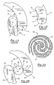
- this type scroll compressor 10 includes an orbiting scroll wrap 11 and a fixed scroll wrap 12.
- the orbiting scroll wrap 11 is shown at a point immediately after completion of discharge.
- Orbiting scroll wrap 1 closes off the majority of the discharge port 13.
- the wraps 11 and 12 have an outer surface 14 that is essentially centered on a first radius R1 and a second surface 15 immediately following surface 14 which is centered on a second radius R2.
- the fixed scroll wrap 12 is shown with the radii defined, the same configuration is preferably utilized to form the scroll wrap for the orbiting scroll 11.
- Figure 1B shows an attempt to minimize the trapped fluid in the type of scroll compressor such as shown in Figure 1A.
- the wrap 19 includes outer portion 14 and rear portion 15 centered on the radii R1 and R2.
- a groove 22 is cut into the surface 15. This creates a chamber wherein the previously trapped fluid can be received such that the above-discussed problem does not occur.
- a line 23 extended from the surface 15 on the radius R2 would meet point 21.
- the restriction 18 as illustrated in Figure 1A still occurs. It is a goal of this invention to eliminate such restriction such that both compression chambers are quickly opened to the discharge port.
- JP-A-62087601 discloses the preamble to claim 1.
- the scroll compressor of the present invention is characterised over this disclosure by the characterising portion of Claim 1.
- the scroll tip geometry is improved such that compression chambers on either side of the orbiting scroll tip open to the discharge port in relatively equal amounts and time.
- the tip geometry could be described as the outer portion of the tip being centered on a first radius and the rear portion of the tip being centered on a second radius, with an interconnecting groove connecting the end of the outer and rear portions.
- the beginning of the groove at the end of the outer portion forms a thinner wrap portion than the end of the groove at the rear portion.
- Each scroll wrap has a tip facing the opposed tip with an outer portion having a forward ledge that merges into a curve, with the curve extending outwardly to a ledge which merges into the rear portion.
- the opposed forward and rear ledges define the ending points of the compression cycle. That is, at the end of a compression cycle, the forward ledge of one scroll wrap contacts the rear ledge of an opposed scroll wrap. As the orbiting scroll begins to move beyond this end point, the shape of the groove ensures that chambers both above and below the inner portion are exposed to the discharge ports in approximately equal amounts and at the same time. The restriction to flow that has occurred in the prior art is thus eliminated.
- the configuration of the tip of the scroll wrap could also be described by defining the swing radius beginning from the origin point of the scroll wrap.
- the swing radius begins on a first side of zero at a point defined between the rear ledge of the fixed scroll and the forward ledge of the orbiting scroll.
- the swing radius moves towards zero, and is soon equal to zero.
- the swing radius then moves to the opposed side of zero at all locations beyond the zero swing radius point. Movement of the swing radius from one side of zero, across zero, and to the other side of zero for the remainder of the wrap is unique for this invention.
- This swing radius behavior provides a scroll wrap tip which achieves the beneficial results described above.
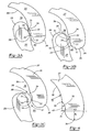
- Figure 2A shows the scroll compressor 24 incorporating a fixed scroll wrap 27 and an orbiting scroll wrap 25.
- An inner portion 26 of the fixed scroll wrap and an inner portion 28 of the orbiting scroll wrap are spaced approximately equally about a center line C.
- the orbiting scroll wrap is seldom in the position illustrated in Figure 2A.
- the orbiting scroll wrap is assumed to be in the position wherein its tip 28 is equally centered about the center C relative to the tip 26 of the fixed scroll 27.
- Figure 2B shows a detail of the inner portion 26 and 28.
- the inner portion have generally the same configuration, and common reference numerals are utilized to describe the geometry of the inner portion.
- a forward portion 30 of the inner portion extends to a forward ledge 31 which merges into a curve 32 leading to a rear ledge 34.
- a rear curve 35 then extends from ledge 34 into the remainder of the scroll wrap.
- the curve 32 curves generally toward the opposed scroll wrap between the forward ledge 31 and the rear ledge 34 such that a forward wrap thickness measured at forward ledge 31 is generally thinner than the wrap at a location aligned with the rear ledge 34.
- the forward face of the wraps could have a configuration other than shown in this figure, and it is possible that the thickness would not meet the above relationship.
- the forward face of the wraps is generally on a common curve, and the wrap is thicker at ledge 34 than it is at ledge 31.
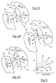
- the wraps 27 and 25 are now at the point where they have completed a discharge cycle.
- the orbiting scroll tip 28 generally covers discharge port 36.
- the forward ledge 31 of the orbiting scroll generally abuts the rear ledge 34 of the fixed scroll.
- the forward ledge 31 of the fixed scroll abuts the rear ledge 34 of the orbiting scroll.
- a compression chamber 38 is defined generally above the tip 28 and a second compression chamber 40 is defined generally between the tip 26 and the opposed wrap 25.
- the next increment of movement of the orbiting scroll essentially is downward as shown in this figure.
- an opening 39 begins to communicate the chamber 38 to the discharge port 36.
- the opening 39 is defined between the rear ledge 34 of the fixed scroll tip 26 and the forward portion 30 of the orbiting scroll.
- the rear ledge 34 of the orbiting scroll is moving along the forward portion 30 of the fixed scroll and defining an opening 41 for the chamber 40 to communicate with the discharge port 36.
- the orbiting scroll has now moved another incremental amount.
- the openings 41 and 39 are generally equal, and do not unduly restrict the flow of fluid from the chambers 38 and 40 to the discharge port 36. This is an improvement over the prior art wraps wherein there was a tight restriction on the chamber 40.
- Figure 4 shows a detail of the tip of one of the scroll wraps.
- the forward ledge 31 begins forward portion 30, which is centered on a radius R1.
- the curve 32 extends back to a rear ledge 34 and a rear curve 35 extends from the rear ledge 34 to a subsequent portion of the wrap.
- the curve 35 is centered on a radius R2.
- An extension 42 is included which extends curve 35, if the curve 35 were to continue to be defined at the radius R2 beyond the ledge 34. As shown, the extension 42 would end at a point 43 which is spaced from the actual ledge 31. This is another way of describing how the wrap is thinner at the forward ledge 31 than it is at the rear ledge 34.
- Figure 4 geometry is described as if the curves 30 and 35 were exactly centered on a single radius.
- the actual wraps may differ from actual circular portions. Even so, this invention extends to scroll wraps having a configuration such that the radius which best fits the scroll curve portions would have the features such as shown in Figure 4.
- Figure 5A through 5C shows another feature of the inventive scroll wrap.
- the center point C lies on a center path 46 between the fixed and orbiting scrolls.
- Path 46 is defined as the central path between the fixed and orbiting scroll wraps.
- a scroll wrap geometry is defined by the generating radius and swing radius at the points along the center path 46.
- a first point 48 is defined at the location between forward ledge 31 of one wrap and the rear ledge 34 of the opposed wrap.
- a vector defined between the center C and the point 48 includes a generating radius portion 54 and a swing radius portion 56.
- the generating radius portion 54 is defined tangent to the path 46 at the point 48.
- the swing radius portion is the vector that needs to be combined with the generating radius to achieve the actual vector extending between the center C and the point 48.
- the swing radius 56 is defined as a negative swing radius and is on a first side of the generating radius 54. Of course, negative and positive are somewhat relative. However, as will be explained with regard to Figures 5B and 5C, in the inventive geometry the swing radius crosses zero and moves to the other side of the center C in this invention.
- a subsequent point 50 has a vector 58 that is equal to the generating radius. That is, at the point 50, a line drawn tangent to the curve 46 would be the vector 58 from the center C to the point 50.
- the initial point has a generating radius which is equal to the vector between the center and the point. When the generating radius is equal to this vector, then the swing radius is zero.
- the vector includes a generating radius portion 60 and a swing radius 62 which is now on an opposed side of the generating radius 60 from the side shown in Figure 5A.
- Line 64 shows the standard scroll compressor that does not have the arc of circle configuration as shown in Figure 1A.
- the entirety of the wrap angles have a positive swing radius.
- Line 66 shows the type of scroll wrap as shown in Figure 1A.
- the initial point has a swing radius of zero and increases with increasing wrap angle.
- the line 68 shows the inventive scroll wrap.
- the initial point 70 is below zero at point 48.
- the swing radius then moves towards zero and crosses zero at point 50.
- the scroll wrap reaches point 52 it has achieved a positive swing radius, and the swing radius will continue to be positive for the remainder of the wrap.
Landscapes
- Engineering & Computer Science (AREA)
- Mechanical Engineering (AREA)
- General Engineering & Computer Science (AREA)
- Rotary Pumps (AREA)
- Structures Of Non-Positive Displacement Pumps (AREA)
Claims (6)
- Compresseur à spirale (24) comprenant :une spirale fixe ayant une base et une enveloppe de spirale (27) s'étendant à partir de ladite base, ladite enveloppe ayant une pointe (26) adjacente à un centre de ladite enveloppe de spirale fixe ;une spirale décrivant une orbite ayant une base et une enveloppe de spirale généralement en spirale (25) s'étendant à partir de ladite base, ladite spirale décrivant une orbite ayant une pointe (28) adjacente à un centre de ladite spirale décrivant une orbite, lesdites enveloppes de spirales décrivant une orbite et fixe s'interconnectant pour définir des chambres de compression (38, 40) ; etladite pointe d'au moins l'une desdites enveloppes de spirales fixe et décrivant une orbite ayant une surface interne faisant face à l'enveloppe opposée, configurée pour avoir un rebord avant (31) adjacent à ladite pointe et un rebord arrière (34) espacé dudit rebord avant dans une direction à distance d'une extrémité située le plus à l'avant de ladite pointe, ledit rebord avant définissant une partie plus fine de ladite enveloppe et ledit rebord arrière définissant une partie plus épaisse de ladite enveloppe, caractérisé en ce que ledit rebord arrière de l'une desdites enveloppes est en contact avec ledit rebord avant de l'autre desdites enveloppes à la fin d'un cycle de compression, et ladite configuration de ladite pointe permet aux chambres de compression définies des deux côtés desdites enveloppes de spirales décrivant une orbite et ne décrivant pas d'orbite de s'ouvrir approximativement de manière identique, après ladite fin dudit cycle de compression.
- Compresseur à spirale (24) selon la revendication 1, dans lequel ladite extrémité située le plus à l'avant de ladite pointe (26, 28) a une forme de courbe avant (30) généralement centrée sur un premier rayon (R1) et s'étendant vers ledit rebord avant (31), une partie de ladite au moins une enveloppe de spirale (25, 27) au-delà dudit rebord arrière (34) a une forme de courbe arrière (35) généralement centrée sur un second rayon (R2) et ladite courbe centrale s'étendant dudit rebord avant audit rebord arrière, ladite courbe arrière étant configurée de sorte que si ladite courbe arrière continue au-delà dudit rebord arrière au niveau dudit second rayon, une extension de ladite courbe arrière est espacée dudit rebord avant vers ladite enveloppe de la spirale opposée.
- Compresseur à spirale (24) selon la revendication 2, dans lequel lesdites enveloppes de spirale (25, 27) ont des surfaces avant qui sont formées sur une courbe.
- Compresseur à spirale (24) selon la revendication 2, dans lequel un rayon de giration pour ladite pointe (26, 28) de ladite au moins une enveloppe de spirale (25, 27) est initialement d'un côté de zéro, se déplace vers une position à laquelle il est égal à zéro, et ensuite traverse zéro et se déplace de l'autre côté de zéro.
- Compresseur à spirale (24) selon la revendication 4, dans lequel à la fois lesdites parties internes de spirale fixe et décrivant une orbite (25, 27) ont ladite configuration.
- Compresseur à spirale (24) selon la revendication 5, dans lequel ladite partie de ladite enveloppe de spirale (25, 27) qui est initialement d'un côté de zéro est définie à un emplacement situé entre un rebord avant (31) d'une enveloppe et un rebord arrière (34) d'une enveloppe opposée.
Applications Claiming Priority (2)
| Application Number | Priority Date | Filing Date | Title |
|---|---|---|---|
| US08/931,702 US6120268A (en) | 1997-09-16 | 1997-09-16 | Scroll compressor with reverse offset at wrap tips |
| US931702 | 2004-09-01 |
Publications (2)
| Publication Number | Publication Date |
|---|---|
| EP0907025A1 EP0907025A1 (fr) | 1999-04-07 |
| EP0907025B1 true EP0907025B1 (fr) | 2005-01-12 |
Family
ID=25461208
Family Applications (1)
| Application Number | Title | Priority Date | Filing Date |
|---|---|---|---|
| EP98305950A Expired - Lifetime EP0907025B1 (fr) | 1997-09-16 | 1998-07-27 | Compresseur à spirale |
Country Status (9)
| Country | Link |
|---|---|
| US (1) | US6120268A (fr) |
| EP (1) | EP0907025B1 (fr) |
| JP (1) | JP3085933B2 (fr) |
| KR (1) | KR100313076B1 (fr) |
| CN (1) | CN1179131C (fr) |
| AU (1) | AU741466B2 (fr) |
| DE (1) | DE69828557T2 (fr) |
| ES (1) | ES2236870T3 (fr) |
| MY (1) | MY114485A (fr) |
Families Citing this family (8)
| Publication number | Priority date | Publication date | Assignee | Title |
|---|---|---|---|---|
| JP4494111B2 (ja) * | 2004-07-28 | 2010-06-30 | アイシン精機株式会社 | スクロール圧縮機 |
| US20070036668A1 (en) * | 2005-08-09 | 2007-02-15 | Carrier Corporation | Scroll compressor discharge port improvements |
| KR100982723B1 (ko) | 2010-05-04 | 2010-09-17 | 최석규 | 여과 물탱크 |
| KR101059880B1 (ko) * | 2011-03-09 | 2011-08-29 | 엘지전자 주식회사 | 스크롤 압축기 |
| FR3070446B1 (fr) | 2017-08-29 | 2020-02-07 | Danfoss Commercial Compressors | Un compresseur a spirales ayant un orifice de refoulement principal central et un orifice de refoulement auxiliaire |
| KR102497530B1 (ko) | 2018-05-28 | 2023-02-08 | 엘지전자 주식회사 | 토출 구조를 개선한 스크롤 압축기 |
| DE102019114481B4 (de) * | 2019-05-29 | 2024-12-19 | Hanon Systems | Spiralverdichter und Verfahren zum Verdichten eines gasförmigen Fluids mit dem Spiralverdichter |
| CN114593048B (zh) * | 2022-03-15 | 2024-11-05 | 冰山松洋压缩机(大连)有限公司 | 一种涡旋压缩机涡旋型线结构 |
Family Cites Families (12)
| Publication number | Priority date | Publication date | Assignee | Title |
|---|---|---|---|---|
| US3874827A (en) * | 1973-10-23 | 1975-04-01 | Niels O Young | Positive displacement scroll apparatus with axially radially compliant scroll member |
| JPS5481513A (en) * | 1977-12-09 | 1979-06-29 | Hitachi Ltd | Scroll compressor |
| AU592756B2 (en) * | 1984-06-18 | 1990-01-25 | Mitsubishi Jukogyo Kabushiki Kaisha | Scroll type fluid machine and method for forming scroll members used therein |
| SE457902B (sv) * | 1984-11-09 | 1989-02-06 | Sanden Corp | Fluidkompressor av spiralhjulstyp med mekanism foer instaellning av deplacementet |
| US4639201A (en) * | 1985-09-12 | 1987-01-27 | Copeland Corporation | Scroll-type machine with variable wrap thickness |
| JPH0612044B2 (ja) * | 1985-10-14 | 1994-02-16 | 三菱重工業株式会社 | 回転式流体機械 |
| US5056336A (en) * | 1989-03-06 | 1991-10-15 | American Standard Inc. | Scroll apparatus with modified scroll profile |
| JP3132928B2 (ja) * | 1992-10-30 | 2001-02-05 | 三菱重工業株式会社 | スクロール型圧縮機 |
| JP3036271B2 (ja) * | 1992-12-03 | 2000-04-24 | 株式会社豊田自動織機製作所 | スクロール型圧縮機 |
| US5342184A (en) * | 1993-05-04 | 1994-08-30 | Copeland Corporation | Scroll machine sound attenuation |
| US5421707A (en) * | 1994-03-07 | 1995-06-06 | General Motors Corporation | Scroll type machine with improved wrap radially outer tip |
| DE19603110A1 (de) * | 1995-11-06 | 1997-05-07 | Bitzer Kuehlmaschinenbau Gmbh | Kompressor |
-
1997
- 1997-09-16 US US08/931,702 patent/US6120268A/en not_active Expired - Lifetime
-
1998
- 1998-07-27 DE DE69828557T patent/DE69828557T2/de not_active Expired - Lifetime
- 1998-07-27 ES ES98305950T patent/ES2236870T3/es not_active Expired - Lifetime
- 1998-07-27 EP EP98305950A patent/EP0907025B1/fr not_active Expired - Lifetime
- 1998-08-31 CN CNB981185657A patent/CN1179131C/zh not_active Expired - Lifetime
- 1998-09-14 JP JP10259997A patent/JP3085933B2/ja not_active Expired - Fee Related
- 1998-09-14 MY MYPI98004191A patent/MY114485A/en unknown
- 1998-09-15 KR KR1019980037984A patent/KR100313076B1/ko not_active Expired - Fee Related
- 1998-09-15 AU AU84234/98A patent/AU741466B2/en not_active Ceased
Also Published As
| Publication number | Publication date |
|---|---|
| JPH11182466A (ja) | 1999-07-06 |
| AU741466B2 (en) | 2001-11-29 |
| CN1179131C (zh) | 2004-12-08 |
| EP0907025A1 (fr) | 1999-04-07 |
| JP3085933B2 (ja) | 2000-09-11 |
| DE69828557T2 (de) | 2005-12-29 |
| DE69828557D1 (de) | 2005-02-17 |
| AU8423498A (en) | 1999-04-01 |
| MY114485A (en) | 2002-10-31 |
| US6120268A (en) | 2000-09-19 |
| KR100313076B1 (ko) | 2002-01-12 |
| KR19990029803A (ko) | 1999-04-26 |
| ES2236870T3 (es) | 2005-07-16 |
| CN1211687A (zh) | 1999-03-24 |
Similar Documents
| Publication | Publication Date | Title |
|---|---|---|
| US5873711A (en) | Scroll compressor with reduced separating force between fixed and orbiting scroll members | |
| US6123528A (en) | Reed discharge valve for scroll compressors | |
| US6231316B1 (en) | Scroll-type variable-capacity compressor | |
| US20040265140A1 (en) | Two-step self-modulating scroll compressor | |
| KR100311888B1 (ko) | 스크롤 압축기용의 비동일형 분사 포트 | |
| EP0907025B1 (fr) | Compresseur à spirale | |
| US6860728B2 (en) | Scroll compressor sealing | |
| US20060266076A1 (en) | Indentation to optimize vapor injection through ports extending through scroll wrap | |
| US6364643B1 (en) | Scroll compressor with dual suction passages which merge into suction path | |
| EP0761971B1 (fr) | Machine à spirales pour des fluides | |
| JPH09177683A (ja) | スクロール形流体機械 | |
| EP0154856B1 (fr) | Compresseur du type à palettes | |
| JPH05321855A (ja) | スクロール型圧縮機におけるシール構造 | |
| EP1913236B1 (fr) | Compresseur à spirale à orifice de décharge amélioré | |
| US6341945B1 (en) | Scroll compressor with reduced capacity at high operating temperatures | |
| US6113372A (en) | Scroll compressor with discharge chamber groove | |
| US4927341A (en) | Scroll machine with relieved flank surface | |
| US6379133B1 (en) | Scroll compressor with reduced stiction surface for check valve | |
| KR100438610B1 (ko) | 스크롤 압축기 | |
| EP0924429B1 (fr) | Compresseur à spirales | |
| KR100315793B1 (ko) | 스크롤 압축기의 냉매 토출구조 | |
| KR100504870B1 (ko) | 스크롤 압축기의 반경방향 실링장치 | |
| JPH0835494A (ja) | スクロール型圧縮機 |
Legal Events
| Date | Code | Title | Description |
|---|---|---|---|
| PUAI | Public reference made under article 153(3) epc to a published international application that has entered the european phase |
Free format text: ORIGINAL CODE: 0009012 |
|
| AK | Designated contracting states |
Kind code of ref document: A1 Designated state(s): BE DE ES FR GB IT |
|
| AX | Request for extension of the european patent |
Free format text: AL;LT;LV;MK;RO;SI |
|
| 17P | Request for examination filed |
Effective date: 19990821 |
|
| AKX | Designation fees paid |
Free format text: BE DE ES FR GB IT |
|
| 17Q | First examination report despatched |
Effective date: 20030318 |
|
| GRAP | Despatch of communication of intention to grant a patent |
Free format text: ORIGINAL CODE: EPIDOSNIGR1 |
|
| GRAS | Grant fee paid |
Free format text: ORIGINAL CODE: EPIDOSNIGR3 |
|
| GRAA | (expected) grant |
Free format text: ORIGINAL CODE: 0009210 |
|
| AK | Designated contracting states |
Kind code of ref document: B1 Designated state(s): BE DE ES FR GB IT |
|
| REG | Reference to a national code |
Ref country code: GB Ref legal event code: FG4D |
|
| REF | Corresponds to: |
Ref document number: 69828557 Country of ref document: DE Date of ref document: 20050217 Kind code of ref document: P |
|
| REG | Reference to a national code |
Ref country code: ES Ref legal event code: FG2A Ref document number: 2236870 Country of ref document: ES Kind code of ref document: T3 |
|
| ET | Fr: translation filed | ||
| PLBE | No opposition filed within time limit |
Free format text: ORIGINAL CODE: 0009261 |
|
| STAA | Information on the status of an ep patent application or granted ep patent |
Free format text: STATUS: NO OPPOSITION FILED WITHIN TIME LIMIT |
|
| 26N | No opposition filed |
Effective date: 20051013 |
|
| PGFP | Annual fee paid to national office [announced via postgrant information from national office to epo] |
Ref country code: FR Payment date: 20090710 Year of fee payment: 12 Ref country code: ES Payment date: 20090812 Year of fee payment: 12 |
|
| PGFP | Annual fee paid to national office [announced via postgrant information from national office to epo] |
Ref country code: GB Payment date: 20090722 Year of fee payment: 12 |
|
| PGFP | Annual fee paid to national office [announced via postgrant information from national office to epo] |
Ref country code: BE Payment date: 20090805 Year of fee payment: 12 |
|
| PGFP | Annual fee paid to national office [announced via postgrant information from national office to epo] |
Ref country code: IT Payment date: 20090725 Year of fee payment: 12 |
|
| BERE | Be: lapsed |
Owner name: *CARRIER CORP. Effective date: 20100731 |
|
| GBPC | Gb: european patent ceased through non-payment of renewal fee |
Effective date: 20100727 |
|
| REG | Reference to a national code |
Ref country code: FR Ref legal event code: ST Effective date: 20110331 |
|
| PG25 | Lapsed in a contracting state [announced via postgrant information from national office to epo] |
Ref country code: FR Free format text: LAPSE BECAUSE OF NON-PAYMENT OF DUE FEES Effective date: 20100802 Ref country code: IT Free format text: LAPSE BECAUSE OF NON-PAYMENT OF DUE FEES Effective date: 20100727 |
|
| PG25 | Lapsed in a contracting state [announced via postgrant information from national office to epo] |
Ref country code: BE Free format text: LAPSE BECAUSE OF NON-PAYMENT OF DUE FEES Effective date: 20100731 |
|
| PG25 | Lapsed in a contracting state [announced via postgrant information from national office to epo] |
Ref country code: GB Free format text: LAPSE BECAUSE OF NON-PAYMENT OF DUE FEES Effective date: 20100727 |
|
| REG | Reference to a national code |
Ref country code: ES Ref legal event code: FD2A Effective date: 20110818 |
|
| PG25 | Lapsed in a contracting state [announced via postgrant information from national office to epo] |
Ref country code: ES Free format text: LAPSE BECAUSE OF NON-PAYMENT OF DUE FEES Effective date: 20100728 |
|
| PGFP | Annual fee paid to national office [announced via postgrant information from national office to epo] |
Ref country code: DE Payment date: 20140724 Year of fee payment: 17 |
|
| REG | Reference to a national code |
Ref country code: DE Ref legal event code: R119 Ref document number: 69828557 Country of ref document: DE |
|
| PG25 | Lapsed in a contracting state [announced via postgrant information from national office to epo] |
Ref country code: DE Free format text: LAPSE BECAUSE OF NON-PAYMENT OF DUE FEES Effective date: 20160202 |