EP0906889B1 - Flaschenfüllvorrichtung mit Füllhöheregelung ohne Flüssigkeitsverlust - Google Patents
Flaschenfüllvorrichtung mit Füllhöheregelung ohne Flüssigkeitsverlust Download PDFInfo
- Publication number
- EP0906889B1 EP0906889B1 EP98450016A EP98450016A EP0906889B1 EP 0906889 B1 EP0906889 B1 EP 0906889B1 EP 98450016 A EP98450016 A EP 98450016A EP 98450016 A EP98450016 A EP 98450016A EP 0906889 B1 EP0906889 B1 EP 0906889B1
- Authority
- EP
- European Patent Office
- Prior art keywords
- liquid
- air return
- cannula
- nozzle
- spout
- Prior art date
- Legal status (The legal status is an assumption and is not a legal conclusion. Google has not performed a legal analysis and makes no representation as to the accuracy of the status listed.)
- Expired - Lifetime
Links
- 239000007788 liquid Substances 0.000 title claims abstract description 30
- 239000000945 filler Substances 0.000 abstract 1
- 239000003570 air Substances 0.000 description 30
- XLYOFNOQVPJJNP-UHFFFAOYSA-N water Substances O XLYOFNOQVPJJNP-UHFFFAOYSA-N 0.000 description 12
- 230000005484 gravity Effects 0.000 description 4
- 239000012080 ambient air Substances 0.000 description 3
- 229910052500 inorganic mineral Inorganic materials 0.000 description 3
- 239000011707 mineral Substances 0.000 description 3
- 238000010586 diagram Methods 0.000 description 2
- 239000012530 fluid Substances 0.000 description 2
- 238000004519 manufacturing process Methods 0.000 description 2
- 210000003323 beak Anatomy 0.000 description 1
- 230000015572 biosynthetic process Effects 0.000 description 1
- 238000011109 contamination Methods 0.000 description 1
- 238000004320 controlled atmosphere Methods 0.000 description 1
- 230000000694 effects Effects 0.000 description 1
- 229920001971 elastomer Polymers 0.000 description 1
- 239000000806 elastomer Substances 0.000 description 1
- 239000012528 membrane Substances 0.000 description 1
- 230000000717 retained effect Effects 0.000 description 1
- 238000013022 venting Methods 0.000 description 1
Images


Classifications
-
- B—PERFORMING OPERATIONS; TRANSPORTING
- B67—OPENING, CLOSING OR CLEANING BOTTLES, JARS OR SIMILAR CONTAINERS; LIQUID HANDLING
- B67C—CLEANING, FILLING WITH LIQUIDS OR SEMILIQUIDS, OR EMPTYING, OF BOTTLES, JARS, CANS, CASKS, BARRELS, OR SIMILAR CONTAINERS, NOT OTHERWISE PROVIDED FOR; FUNNELS
- B67C3/00—Bottling liquids or semiliquids; Filling jars or cans with liquids or semiliquids using bottling or like apparatus; Filling casks or barrels with liquids or semiliquids
- B67C3/02—Bottling liquids or semiliquids; Filling jars or cans with liquids or semiliquids using bottling or like apparatus
- B67C3/22—Details
- B67C3/26—Filling-heads; Means for engaging filling-heads with bottle necks
- B67C3/2637—Filling-heads; Means for engaging filling-heads with bottle necks comprising a liquid valve opened by relative movement between the container and the filling head
-
- B—PERFORMING OPERATIONS; TRANSPORTING
- B67—OPENING, CLOSING OR CLEANING BOTTLES, JARS OR SIMILAR CONTAINERS; LIQUID HANDLING
- B67C—CLEANING, FILLING WITH LIQUIDS OR SEMILIQUIDS, OR EMPTYING, OF BOTTLES, JARS, CANS, CASKS, BARRELS, OR SIMILAR CONTAINERS, NOT OTHERWISE PROVIDED FOR; FUNNELS
- B67C3/00—Bottling liquids or semiliquids; Filling jars or cans with liquids or semiliquids using bottling or like apparatus; Filling casks or barrels with liquids or semiliquids
- B67C3/02—Bottling liquids or semiliquids; Filling jars or cans with liquids or semiliquids using bottling or like apparatus
- B67C3/22—Details
- B67C3/26—Filling-heads; Means for engaging filling-heads with bottle necks
- B67C2003/2651—The liquid valve being carried by the vent tube
Definitions
- the present invention relates to a device for filling bottles with a liquid and leveling that liquid in these bottles without loss of fluid.
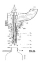
- This spout of the prior art includes in a simplified manner a tank 10 in which the liquid 12 is stored with which the bottle 14.
- the bottle 14 is brought under the spout for its filling.
- the spout is fixed and the bottle is mobile in vertical translation to cause filling as it is going to be explained later.
- the spout comprises a cannula 16 for air return and guide, fixed in translation with a end piece 18 and its end 19, attached to the lower end of this cannula, a nozzle body 20, coaxial with the cannula and movable between two positions relative to said cannula, a first position in which this body cooperates tightly with the nozzle 18, preventing any flow and a second position in which this body is raised relative to the nozzle 18, letting the liquid flow.
- connection means 22 with elastic return are interposed between the tank and the spout body, in this case, a membrane in elastomer.
- These connecting means have a double function, the first of allow continuity of flow between the tank and the bottle and the second to recall the spout body so that its end is pressed sealingly against the nozzle 18 outside the filling phases.
- the spout of the prior art further comprises an air return tube 24 which allows you to remove the random side of the upgrade at the end of filling.
- This return air tube opens out through an opening 25 in the wall of the spout body 20.
- This tube has an industrial drawback, it must be housed between the cannula and the nozzle body, in a relatively narrow space. Her manufacturing and its implementation are quite delicate. We also note that it can friction occurs between the cannula 16 and the air return tube 24 because the operating clearances are very small as explained above.
- the bottle When the filling takes place, the bottle is lifted until its neck 26 comes to bear sealingly against a flange 28, integral with the body 20 of the spout.
- the bottle is lowered to allow the connecting means and reminder to stop the flow and at the neck 26 of the bottle take off from the collar 28.
- the orifice 25 is no longer obstructed.
- a slight depression is generally maintained above the level of the liquid in the tank and the cannula opens into this sky in slight depression. This therefore makes it possible to exert this slight depression in the bottle, through the cannula, which has the effect of sucking the liquid through the cannula 16, the sucked liquid then flowing in the tank at the outlet of the upper end of said cannula. This aspiration continues until the level of the liquid is at H 0 , that is to say at the level of the lower end of the cannula. Therefore, the level of the liquid is identical for all the bottles since the nozzle 18 is fixed.
- the solution currently consists of vacuuming the water and reject it, which causes significant water losses, while must manage the quantities used as accurately as possible.
- the device according to the invention allows filling of bottles, especially with mineral water, which prevents any loss of water, which allows keep the same upgrades for all bottles, especially when this device is mounted on carousels of tall machines rates, which eliminates the delicate assembly of the return tube air between the body of the spout and the cannula, which is more adaptable on the existing machines and which avoids mixing and / or contact air / water mentioned above.
- the device for filling bottles of the type comprising a filling spout connected to a tank containing a liquid bottle by connecting means, this spout comprising an air return cannula with a tip fixed in translation relative to a spout body movable in translation between a first position in which the liquid can flow between said nozzle body and end piece, and a second position in which said body spout is in tight contact with the nozzle, characterized in that it comprises a return air tube which is coaxial with the cannula and inside the nozzle body and which opens through at least one radial opening, substantially at the right of the nozzle and up to the end of the tube of the nozzle body.
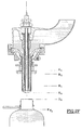
- the air return and guide cannula opens at a height H 0 and the opening of the free air return tube opens at a height H 1 located above that of the cannula.
- the opening of the air return tube As for the opening of the air return tube, it opens substantially radially and that of the cannula opens vertically through an opening and constitutes the low point H 0 of the nozzle and the spout.
- the cannula and the return tube of air are at atmospheric pressure.
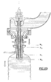
- FIG. 2A a beak is shown, the identical or at least who play the same role, have the same references as those in Figure 1 but increased by 100.
- a tank is referenced 110.
- the air return tube 124 is on the other hand arranged differently.
- this air return tube 124 is mounted coaxial outside the cannula 116, also fixed in translation like said cannula and inside the spout body 120.
- the lower end 130 of this air return tube 124 opens laterally through three openings 125, in the nozzle 118, above from the lower end 119 of the cannula.
- the upper end of this tube 124 opens into the open air, in a known manner.
- the end of the neck 126 can take at least three positions: H 2 waiting, H 3 contact and H 4 filling.
- the neck of the bottle is in the standby position H 2
- the spout is closed because the body 120 of the spout is in the low position and comes into tight contact with the nozzle 118 Likewise, it can be seen that the opening 125 of the air return tube 124 is closed.
- the bottle 114 has its neck 126 which is brought to level H 4 , after having come into contact with the flange 128 in H 3 , which causes the body 120 to be raised from the spout and the flow of the contents of the tank inside the bottle, provided that the tank is filled.
- the neck 126 being in leaktight contact with the collar 128, the air return openings 116 and 125 ensure the evacuation of the air contained in the bottle, allowing gravity filling, without any brake the flow.
- the flow of the tank is stopped by lowering the neck 126 to level H 3 , which brings the body 120 of the spout back into its sealed closing position by also closing the opening 125 and preventing any flow of the liquid contained in the air return tube 124.
- the filled bottle can be brought back to its position H 2 ready to be capped thereafter by any suitable means. It is noted that the air return tube 124 always contains the liquid which flows in the next bottle treated by the same spout from the start of filling, which does not disturb the leveling in the next bottle.
- the device according to the present invention has a certain advantage as for industrial manufacturing because the mounting of coaxial tubes with a radial outlet is relatively simple and moreover the venting is carried out by means of a section greater than that of the small tube of the prior art, this which promotes flow and avoids any torch spout.
- the device which has just been described can be put into service so identical in a filling system using a filling system pressure / vacuum in controlled atmosphere for leveling.
- the filling speed can be adjusted by height variations load or by variations in pressure / vacuum in the event that the layout uses them or by combined adjustment of these various parameters.
Landscapes
- Filling Of Jars Or Cans And Processes For Cleaning And Sealing Jars (AREA)
- Basic Packing Technique (AREA)
Claims (4)
- Flaschen-Befüllungsvorrichtung des Typs, der eine Befüllungstülle aufweist, die über Verbindungsmittel (122) mit einem Behälter (110) verbunden ist, der eine in Flaschen abzufüllende Flüssigkeit (112) enthält, wobei diese Tülle eine Luftrückführungskanüle (116) aufweist, die ein Ansatzstück (118) aufweist, das in bezug auf einen Körper (120) der Tülle translatorisch fest ist, wobei der Körper (120) seinerseits zwischen einer ersten Position, in der die Flüssigkeit zwischen dem Körper der Tülle und dem Ansatzstück fließen kann, und einer zweiten Position, in der der Körper der Tülle mit dem Ansatzstück in dichtem Kontakt ist, translatorisch beweglich ist, dadurch gekennzeichnet, daß sie ein Luflrückführungsrohr (124) aufweist, das zur Kanüle (116) koaxial ist, sich innerhalb des Körpers (120) der Tülle befindet und durch wenigstens eine radiale Öffnung (125) im wesentlichen in der Verlängerung des Ansatzstücks und auf Höhe des Endes des Rohrs des Körpers (120) der Tülle nach außen mündet.
- Befüllungsvorrichtung nach Anspruch 1, dadurch gekennzeichnet, daß die Luftrückführungs- und Führungskanüle (116) auf einer Höhe H0 nach außen mündet und die Öffnung (125) des Lüftrückführungsrohrs (124) auf einer Höhe H1, die sich über jener der Kanüle befindet, nach außen mündet.
- Befüllungsvorrichtung nach Anspruch 2, dadurch gekennzeichnet, daß die Kanüle (116) durch eine Öffnung (119) vertikal nach außen mündet und den unteren Punkt H0 des Ansatzstücks und der Tülle bildet.
- Befüllungsvorrichtung nach einem der Ansprüche 1 bis 3, dadurch gekennzeichnet, daß in der Kanüle (116) und im Luftrückführungsrohr (124) Atmosphärendruck herrscht.
Applications Claiming Priority (2)
| Application Number | Priority Date | Filing Date | Title |
|---|---|---|---|
| FR9712725 | 1997-10-03 | ||
| FR9712725A FR2769303B1 (fr) | 1997-10-03 | 1997-10-03 | Dispositif d'emplissage de bouteilles avec mise a niveau du liquide dans lesdites bouteilles, sans perte de liquide |
Publications (2)
| Publication Number | Publication Date |
|---|---|
| EP0906889A1 EP0906889A1 (de) | 1999-04-07 |
| EP0906889B1 true EP0906889B1 (de) | 2001-03-21 |
Family
ID=9512117
Family Applications (1)
| Application Number | Title | Priority Date | Filing Date |
|---|---|---|---|
| EP98450016A Expired - Lifetime EP0906889B1 (de) | 1997-10-03 | 1998-10-01 | Flaschenfüllvorrichtung mit Füllhöheregelung ohne Flüssigkeitsverlust |
Country Status (4)
| Country | Link |
|---|---|
| EP (1) | EP0906889B1 (de) |
| AT (1) | ATE199879T1 (de) |
| DE (1) | DE69800617D1 (de) |
| FR (1) | FR2769303B1 (de) |
Families Citing this family (2)
| Publication number | Priority date | Publication date | Assignee | Title |
|---|---|---|---|---|
| FR2849011A1 (fr) * | 2002-12-23 | 2004-06-25 | Sources 77 Sa | Procede de remplissage automatique de contenants pour liquides alimentaires et appareil mettant en oeuvre ce procede |
| ITPD20060015A1 (it) * | 2006-01-18 | 2007-07-19 | Acqua Minerale S Benedetto Spa | Valvola per il riempimento di bottiglie, da utilizzarsi in impianti industriali di imbottigliamento in ambiente asettico per succhi, bibite e in genere per bevande cosiddette piatte |
Family Cites Families (1)
| Publication number | Priority date | Publication date | Assignee | Title |
|---|---|---|---|---|
| FR2466433A1 (fr) * | 1979-10-05 | 1981-04-10 | Bedin Jean | Bec d'emplissage |
-
1997
- 1997-10-03 FR FR9712725A patent/FR2769303B1/fr not_active Expired - Fee Related
-
1998
- 1998-10-01 EP EP98450016A patent/EP0906889B1/de not_active Expired - Lifetime
- 1998-10-01 AT AT98450016T patent/ATE199879T1/de not_active IP Right Cessation
- 1998-10-01 DE DE69800617T patent/DE69800617D1/de not_active Expired - Lifetime
Also Published As
| Publication number | Publication date |
|---|---|
| FR2769303A1 (fr) | 1999-04-09 |
| DE69800617D1 (de) | 2001-04-26 |
| FR2769303B1 (fr) | 1999-12-31 |
| EP0906889A1 (de) | 1999-04-07 |
| ATE199879T1 (de) | 2001-04-15 |
Similar Documents
| Publication | Publication Date | Title |
|---|---|---|
| EP0597161B1 (de) | Kombinierte Vorrichtung zum Abziehen von Flüssigkeit und Reinigungsgerät dafür | |
| EP0487412A1 (de) | Dosierventil für in einem drucklosen Behälter enthaltenen Flüssigkeiten | |
| CA2416556C (fr) | Bec de remplissage a jet en parapluie et machine de remplissage munie d'un tel bec | |
| FR2568864A1 (fr) | Dispositif de remplissage de recipient, notamment dispositif pour remplir des bouteilles | |
| EP1045814B1 (de) | Füllungsbegrenzer für flüssigkeitslagerbehälter | |
| FR2933380A1 (fr) | Procede de conditionnement de produit fluide dans un distributeur | |
| EP0906889B1 (de) | Flaschenfüllvorrichtung mit Füllhöheregelung ohne Flüssigkeitsverlust | |
| EP2758332B1 (de) | Verfahren und ausgiesser für eine flüssigkeitsbefüllung mit konstantem pegel | |
| EP1804926A1 (de) | Durchflussgeregelter niederdruck-pulververteiler | |
| EP0383707B1 (de) | Gegendruck-Abfüllkopf für kohlensäurehaltige Flüssigkeiten | |
| FR2677007A1 (fr) | Bec de soutirage, machine de soutirage equipee de ce bec et procede de mise en óoeuvre de ce bec. | |
| FR2552749A1 (fr) | Dispositif de remplissage automatique de bouteilles, notamment par des liquides carbonates | |
| EP2758333A1 (de) | Gesteuerte abgasvorrichtung im zusammenhang mit einer vorrichtung zur ausgabe unter druck von flüssigkeit in einen behälter | |
| EP1082265A1 (de) | Füllventil | |
| WO2002024524A1 (fr) | Dispositif de remplissage de liquide a fermeture automatique | |
| EP0792665A1 (de) | Flüssigkeitszerstäubungsfeuerlöscher | |
| FR2507587A1 (fr) | Dispositif de distribution de boisson par tirage sous pression | |
| FR2997931A1 (fr) | Dispositif pour gouter un vin en bouteille et machine pour deboucher et reboucher une bouteille equipee dudit dispositif | |
| FR3032443A1 (fr) | Dispositif de distribution et de conservation de liquide contenu dans un recipient de type bouteille a corps rotatif | |
| EP1022249A1 (de) | Dosiervorrichtung für volumetrische Abfülleinrichtung | |
| FR2675793A1 (fr) | Dispositif de soutirage, notamment lors d'une operation d'embouteillage du vin et son dispositif de lavage automatique. | |
| FR2564936A1 (fr) | Robinet de mise a niveau | |
| FR2547644A1 (fr) | Dispositif de lubrification d'air comprime | |
| LU88646A1 (fr) | Dispositif de remplissage d'un réservoir de gaz liquéfié | |
| FR2730983A1 (fr) | Dispositif d'obturation de l'aspiration en phase transfert d'un poste de soutirage de liquide par depression |
Legal Events
| Date | Code | Title | Description |
|---|---|---|---|
| PUAI | Public reference made under article 153(3) epc to a published international application that has entered the european phase |
Free format text: ORIGINAL CODE: 0009012 |
|
| AK | Designated contracting states |
Kind code of ref document: A1 Designated state(s): AT BE CH DE ES FR GB GR IE IT LI LU MC NL PT SE |
|
| AX | Request for extension of the european patent |
Free format text: AL;LT;LV;MK;RO;SI |
|
| 17P | Request for examination filed |
Effective date: 19990921 |
|
| AKX | Designation fees paid |
Free format text: AT BE CH DE ES FR GB GR IE IT LI LU MC NL PT SE |
|
| RAP1 | Party data changed (applicant data changed or rights of an application transferred) |
Owner name: SIDEL PARTICIPATIONS INDUSTRIELLES |
|
| GRAG | Despatch of communication of intention to grant |
Free format text: ORIGINAL CODE: EPIDOS AGRA |
|
| 17Q | First examination report despatched |
Effective date: 20000406 |
|
| GRAG | Despatch of communication of intention to grant |
Free format text: ORIGINAL CODE: EPIDOS AGRA |
|
| GRAH | Despatch of communication of intention to grant a patent |
Free format text: ORIGINAL CODE: EPIDOS IGRA |
|
| GRAH | Despatch of communication of intention to grant a patent |
Free format text: ORIGINAL CODE: EPIDOS IGRA |
|
| GRAA | (expected) grant |
Free format text: ORIGINAL CODE: 0009210 |
|
| AK | Designated contracting states |
Kind code of ref document: B1 Designated state(s): AT BE CH DE ES FR GB GR IE IT LI LU MC NL PT SE |
|
| PG25 | Lapsed in a contracting state [announced via postgrant information from national office to epo] |
Ref country code: NL Free format text: LAPSE BECAUSE OF FAILURE TO SUBMIT A TRANSLATION OF THE DESCRIPTION OR TO PAY THE FEE WITHIN THE PRESCRIBED TIME-LIMIT Effective date: 20010321 Ref country code: IT Free format text: LAPSE BECAUSE OF FAILURE TO SUBMIT A TRANSLATION OF THE DESCRIPTION OR TO PAY THE FEE WITHIN THE PRESCRIBED TIME-LIMIT;WARNING: LAPSES OF ITALIAN PATENTS WITH EFFECTIVE DATE BEFORE 2007 MAY HAVE OCCURRED AT ANY TIME BEFORE 2007. THE CORRECT EFFECTIVE DATE MAY BE DIFFERENT FROM THE ONE RECORDED. Effective date: 20010321 Ref country code: IE Free format text: LAPSE BECAUSE OF FAILURE TO SUBMIT A TRANSLATION OF THE DESCRIPTION OR TO PAY THE FEE WITHIN THE PRESCRIBED TIME-LIMIT Effective date: 20010321 Ref country code: GB Free format text: LAPSE BECAUSE OF FAILURE TO SUBMIT A TRANSLATION OF THE DESCRIPTION OR TO PAY THE FEE WITHIN THE PRESCRIBED TIME-LIMIT Effective date: 20010321 Ref country code: AT Free format text: LAPSE BECAUSE OF FAILURE TO SUBMIT A TRANSLATION OF THE DESCRIPTION OR TO PAY THE FEE WITHIN THE PRESCRIBED TIME-LIMIT Effective date: 20010321 |
|
| REF | Corresponds to: |
Ref document number: 199879 Country of ref document: AT Date of ref document: 20010415 Kind code of ref document: T |
|
| REG | Reference to a national code |
Ref country code: CH Ref legal event code: EP |
|
| REG | Reference to a national code |
Ref country code: IE Ref legal event code: FG4D Free format text: FRENCH |
|
| REF | Corresponds to: |
Ref document number: 69800617 Country of ref document: DE Date of ref document: 20010426 |
|
| PG25 | Lapsed in a contracting state [announced via postgrant information from national office to epo] |
Ref country code: SE Free format text: LAPSE BECAUSE OF FAILURE TO SUBMIT A TRANSLATION OF THE DESCRIPTION OR TO PAY THE FEE WITHIN THE PRESCRIBED TIME-LIMIT Effective date: 20010621 Ref country code: PT Free format text: LAPSE BECAUSE OF FAILURE TO SUBMIT A TRANSLATION OF THE DESCRIPTION OR TO PAY THE FEE WITHIN THE PRESCRIBED TIME-LIMIT Effective date: 20010621 |
|
| PG25 | Lapsed in a contracting state [announced via postgrant information from national office to epo] |
Ref country code: GR Free format text: LAPSE BECAUSE OF FAILURE TO SUBMIT A TRANSLATION OF THE DESCRIPTION OR TO PAY THE FEE WITHIN THE PRESCRIBED TIME-LIMIT Effective date: 20010622 Ref country code: DE Free format text: LAPSE BECAUSE OF FAILURE TO SUBMIT A TRANSLATION OF THE DESCRIPTION OR TO PAY THE FEE WITHIN THE PRESCRIBED TIME-LIMIT Effective date: 20010622 |
|
| REG | Reference to a national code |
Ref country code: CH Ref legal event code: NV Representative=s name: MICHELI & CIE INGENIEURS-CONSEILS |
|
| NLV1 | Nl: lapsed or annulled due to failure to fulfill the requirements of art. 29p and 29m of the patents act | ||
| GBV | Gb: ep patent (uk) treated as always having been void in accordance with gb section 77(7)/1977 [no translation filed] |
Effective date: 20010321 |
|
| PG25 | Lapsed in a contracting state [announced via postgrant information from national office to epo] |
Ref country code: ES Free format text: LAPSE BECAUSE OF FAILURE TO SUBMIT A TRANSLATION OF THE DESCRIPTION OR TO PAY THE FEE WITHIN THE PRESCRIBED TIME-LIMIT Effective date: 20010927 |
|
| PG25 | Lapsed in a contracting state [announced via postgrant information from national office to epo] |
Ref country code: MC Free format text: LAPSE BECAUSE OF NON-PAYMENT OF DUE FEES Effective date: 20011001 |
|
| REG | Reference to a national code |
Ref country code: IE Ref legal event code: FD4D |
|
| PLBE | No opposition filed within time limit |
Free format text: ORIGINAL CODE: 0009261 |
|
| STAA | Information on the status of an ep patent application or granted ep patent |
Free format text: STATUS: NO OPPOSITION FILED WITHIN TIME LIMIT |
|
| 26N | No opposition filed | ||
| PGFP | Annual fee paid to national office [announced via postgrant information from national office to epo] |
Ref country code: FR Payment date: 20021031 Year of fee payment: 5 |
|
| PGFP | Annual fee paid to national office [announced via postgrant information from national office to epo] |
Ref country code: LU Payment date: 20021107 Year of fee payment: 5 |
|
| PGFP | Annual fee paid to national office [announced via postgrant information from national office to epo] |
Ref country code: CH Payment date: 20021108 Year of fee payment: 5 |
|
| PGFP | Annual fee paid to national office [announced via postgrant information from national office to epo] |
Ref country code: BE Payment date: 20021210 Year of fee payment: 5 |
|
| PG25 | Lapsed in a contracting state [announced via postgrant information from national office to epo] |
Ref country code: LU Free format text: LAPSE BECAUSE OF NON-PAYMENT OF DUE FEES Effective date: 20031001 |
|
| PG25 | Lapsed in a contracting state [announced via postgrant information from national office to epo] |
Ref country code: LI Free format text: LAPSE BECAUSE OF NON-PAYMENT OF DUE FEES Effective date: 20031031 Ref country code: CH Free format text: LAPSE BECAUSE OF NON-PAYMENT OF DUE FEES Effective date: 20031031 Ref country code: BE Free format text: LAPSE BECAUSE OF NON-PAYMENT OF DUE FEES Effective date: 20031031 |
|
| BERE | Be: lapsed |
Owner name: S.A. *SIDEL PARTICIPATIONS INDUSTRIELLES Effective date: 20031031 |
|
| REG | Reference to a national code |
Ref country code: CH Ref legal event code: PL |
|
| PG25 | Lapsed in a contracting state [announced via postgrant information from national office to epo] |
Ref country code: FR Free format text: LAPSE BECAUSE OF NON-PAYMENT OF DUE FEES Effective date: 20040630 |
|
| REG | Reference to a national code |
Ref country code: FR Ref legal event code: ST |