EP0906889B1 - Bottle filling device with liquid level adjustment without loss of liquid - Google Patents
Bottle filling device with liquid level adjustment without loss of liquid Download PDFInfo
- Publication number
- EP0906889B1 EP0906889B1 EP98450016A EP98450016A EP0906889B1 EP 0906889 B1 EP0906889 B1 EP 0906889B1 EP 98450016 A EP98450016 A EP 98450016A EP 98450016 A EP98450016 A EP 98450016A EP 0906889 B1 EP0906889 B1 EP 0906889B1
- Authority
- EP
- European Patent Office
- Prior art keywords
- liquid
- air return
- cannula
- nozzle
- spout
- Prior art date
- Legal status (The legal status is an assumption and is not a legal conclusion. Google has not performed a legal analysis and makes no representation as to the accuracy of the status listed.)
- Expired - Lifetime
Links
Images


Classifications
-
- B—PERFORMING OPERATIONS; TRANSPORTING
- B67—OPENING, CLOSING OR CLEANING BOTTLES, JARS OR SIMILAR CONTAINERS; LIQUID HANDLING
- B67C—CLEANING, FILLING WITH LIQUIDS OR SEMILIQUIDS, OR EMPTYING, OF BOTTLES, JARS, CANS, CASKS, BARRELS, OR SIMILAR CONTAINERS, NOT OTHERWISE PROVIDED FOR; FUNNELS
- B67C3/00—Bottling liquids or semiliquids; Filling jars or cans with liquids or semiliquids using bottling or like apparatus; Filling casks or barrels with liquids or semiliquids
- B67C3/02—Bottling liquids or semiliquids; Filling jars or cans with liquids or semiliquids using bottling or like apparatus
- B67C3/22—Details
- B67C3/26—Filling-heads; Means for engaging filling-heads with bottle necks
- B67C3/2637—Filling-heads; Means for engaging filling-heads with bottle necks comprising a liquid valve opened by relative movement between the container and the filling head
-
- B—PERFORMING OPERATIONS; TRANSPORTING
- B67—OPENING, CLOSING OR CLEANING BOTTLES, JARS OR SIMILAR CONTAINERS; LIQUID HANDLING
- B67C—CLEANING, FILLING WITH LIQUIDS OR SEMILIQUIDS, OR EMPTYING, OF BOTTLES, JARS, CANS, CASKS, BARRELS, OR SIMILAR CONTAINERS, NOT OTHERWISE PROVIDED FOR; FUNNELS
- B67C3/00—Bottling liquids or semiliquids; Filling jars or cans with liquids or semiliquids using bottling or like apparatus; Filling casks or barrels with liquids or semiliquids
- B67C3/02—Bottling liquids or semiliquids; Filling jars or cans with liquids or semiliquids using bottling or like apparatus
- B67C3/22—Details
- B67C3/26—Filling-heads; Means for engaging filling-heads with bottle necks
- B67C2003/2651—The liquid valve being carried by the vent tube
Definitions
- the present invention relates to a device for filling bottles with a liquid and leveling that liquid in these bottles without loss of fluid.
- This spout of the prior art includes in a simplified manner a tank 10 in which the liquid 12 is stored with which the bottle 14.
- the bottle 14 is brought under the spout for its filling.
- the spout is fixed and the bottle is mobile in vertical translation to cause filling as it is going to be explained later.
- the spout comprises a cannula 16 for air return and guide, fixed in translation with a end piece 18 and its end 19, attached to the lower end of this cannula, a nozzle body 20, coaxial with the cannula and movable between two positions relative to said cannula, a first position in which this body cooperates tightly with the nozzle 18, preventing any flow and a second position in which this body is raised relative to the nozzle 18, letting the liquid flow.
- connection means 22 with elastic return are interposed between the tank and the spout body, in this case, a membrane in elastomer.
- These connecting means have a double function, the first of allow continuity of flow between the tank and the bottle and the second to recall the spout body so that its end is pressed sealingly against the nozzle 18 outside the filling phases.
- the spout of the prior art further comprises an air return tube 24 which allows you to remove the random side of the upgrade at the end of filling.
- This return air tube opens out through an opening 25 in the wall of the spout body 20.
- This tube has an industrial drawback, it must be housed between the cannula and the nozzle body, in a relatively narrow space. Her manufacturing and its implementation are quite delicate. We also note that it can friction occurs between the cannula 16 and the air return tube 24 because the operating clearances are very small as explained above.
- the bottle When the filling takes place, the bottle is lifted until its neck 26 comes to bear sealingly against a flange 28, integral with the body 20 of the spout.
- the bottle is lowered to allow the connecting means and reminder to stop the flow and at the neck 26 of the bottle take off from the collar 28.
- the orifice 25 is no longer obstructed.
- a slight depression is generally maintained above the level of the liquid in the tank and the cannula opens into this sky in slight depression. This therefore makes it possible to exert this slight depression in the bottle, through the cannula, which has the effect of sucking the liquid through the cannula 16, the sucked liquid then flowing in the tank at the outlet of the upper end of said cannula. This aspiration continues until the level of the liquid is at H 0 , that is to say at the level of the lower end of the cannula. Therefore, the level of the liquid is identical for all the bottles since the nozzle 18 is fixed.
- the solution currently consists of vacuuming the water and reject it, which causes significant water losses, while must manage the quantities used as accurately as possible.
- the device according to the invention allows filling of bottles, especially with mineral water, which prevents any loss of water, which allows keep the same upgrades for all bottles, especially when this device is mounted on carousels of tall machines rates, which eliminates the delicate assembly of the return tube air between the body of the spout and the cannula, which is more adaptable on the existing machines and which avoids mixing and / or contact air / water mentioned above.
- the device for filling bottles of the type comprising a filling spout connected to a tank containing a liquid bottle by connecting means, this spout comprising an air return cannula with a tip fixed in translation relative to a spout body movable in translation between a first position in which the liquid can flow between said nozzle body and end piece, and a second position in which said body spout is in tight contact with the nozzle, characterized in that it comprises a return air tube which is coaxial with the cannula and inside the nozzle body and which opens through at least one radial opening, substantially at the right of the nozzle and up to the end of the tube of the nozzle body.
- the air return and guide cannula opens at a height H 0 and the opening of the free air return tube opens at a height H 1 located above that of the cannula.
- the opening of the air return tube As for the opening of the air return tube, it opens substantially radially and that of the cannula opens vertically through an opening and constitutes the low point H 0 of the nozzle and the spout.
- the cannula and the return tube of air are at atmospheric pressure.
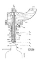
- FIG. 2A a beak is shown, the identical or at least who play the same role, have the same references as those in Figure 1 but increased by 100.
- a tank is referenced 110.
- the air return tube 124 is on the other hand arranged differently.
- this air return tube 124 is mounted coaxial outside the cannula 116, also fixed in translation like said cannula and inside the spout body 120.
- the lower end 130 of this air return tube 124 opens laterally through three openings 125, in the nozzle 118, above from the lower end 119 of the cannula.
- the upper end of this tube 124 opens into the open air, in a known manner.
- the end of the neck 126 can take at least three positions: H 2 waiting, H 3 contact and H 4 filling.
- the neck of the bottle is in the standby position H 2
- the spout is closed because the body 120 of the spout is in the low position and comes into tight contact with the nozzle 118 Likewise, it can be seen that the opening 125 of the air return tube 124 is closed.
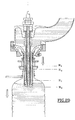
- the bottle 114 has its neck 126 which is brought to level H 4 , after having come into contact with the flange 128 in H 3 , which causes the body 120 to be raised from the spout and the flow of the contents of the tank inside the bottle, provided that the tank is filled.
- the neck 126 being in leaktight contact with the collar 128, the air return openings 116 and 125 ensure the evacuation of the air contained in the bottle, allowing gravity filling, without any brake the flow.
- the flow of the tank is stopped by lowering the neck 126 to level H 3 , which brings the body 120 of the spout back into its sealed closing position by also closing the opening 125 and preventing any flow of the liquid contained in the air return tube 124.
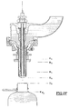
- the filled bottle can be brought back to its position H 2 ready to be capped thereafter by any suitable means. It is noted that the air return tube 124 always contains the liquid which flows in the next bottle treated by the same spout from the start of filling, which does not disturb the leveling in the next bottle.
- the device according to the present invention has a certain advantage as for industrial manufacturing because the mounting of coaxial tubes with a radial outlet is relatively simple and moreover the venting is carried out by means of a section greater than that of the small tube of the prior art, this which promotes flow and avoids any torch spout.
- the device which has just been described can be put into service so identical in a filling system using a filling system pressure / vacuum in controlled atmosphere for leveling.
- the filling speed can be adjusted by height variations load or by variations in pressure / vacuum in the event that the layout uses them or by combined adjustment of these various parameters.
Landscapes
- Filling Of Jars Or Cans And Processes For Cleaning And Sealing Jars (AREA)
- Basic Packing Technique (AREA)
Abstract
Description
La présente invention concerne un dispositif d'emplissage de bouteilles avec un liquide et de mise à niveau de ce liquide dans ces bouteilles, sans perte de liquide.The present invention relates to a device for filling bottles with a liquid and leveling that liquid in these bottles without loss of fluid.
On connaít un bec d'emplissage tel que celui représenté à titre indicatif
sur la figure 1. Ce bec de l'art antérieur (voir FR-A-2 466 433) comprend de façon simplifiée une
cuve 10 dans laquelle est conservé le liquide 12 dont on doit emplir la
bouteille 14.We know a filling spout such as that shown for information
in FIG. 1. This spout of the prior art (see FR-A-2 466 433) includes in a simplified manner a
La bouteille 14 est amenée sous le bec pour son emplissage. On note
que dans ce type de bec de l'art antérieur, le bec est fixe et la bouteille est
mobile en translation verticale pour provoquer l'emplissage comme cela va être
expliqué ultérieurement.The
Ainsi que montré sur la figure 1 des dessins annexés, le bec comprend
une canule 16 de retour d'air et de guidage, fixe en translation avec un
embout 18 et son extrémité 19, rapporté à l'extrémité inférieure de cette
canule, un corps 20 de bec, coaxial à la canule et mobile entre deux positions
par rapport à ladite canule, une première position dans laquelle ce corps
coopère de façon étanche avec l'embout 18, interdisant tout écoulement et
une seconde position dans laquelle ce corps est soulevé par rapport à
l'embout 18, laissant s'écouler le liquide.As shown in Figure 1 of the accompanying drawings, the spout comprises
a
De plus, des moyens 22 de liaison souple avec rappel élastique, sont
interposés entre la cuve et le corps de bec, en l'occurrence, une membrane en
élastomère. Ces moyens de liaison ont une double fonction, la première de
permettre une continuité de l'écoulement entre la cuve et la bouteille et la
seconde de rappeler le corps de bec pour que son extrémité soit plaquée de
façon étanche contre l'embout 18 en dehors des phases d'emplissage.In addition, flexible connection means 22 with elastic return are
interposed between the tank and the spout body, in this case, a membrane in
elastomer. These connecting means have a double function, the first of
allow continuity of flow between the tank and the bottle and the
second to recall the spout body so that its end is pressed
sealingly against the
Le bec de l'art antérieur comprend de plus un tube 24 de retour d'air qui
permet de supprimer le côté aléatoire de la mise à niveau à la fin de
l'emplissage. Ce tube de retour d'air débouche par une ouverture 25 ménagée
dans la paroi du corps 20 de bec.The spout of the prior art further comprises an
Ce tube présente un inconvénient industriel, c'est qu'il doit être logé
entre la canule et le corps de bec, dans un espace relativement étroit. Sa
fabrication et sa mise en place sont assez délicates. On note aussi qu'il peut
se produire des frottements entre la canule 16 et le tube 24 de retour d'air car
les jeux de fonctionnement sont très faibles comme on l'a expliqué ci-avant.This tube has an industrial drawback, it must be housed
between the cannula and the nozzle body, in a relatively narrow space. Her
manufacturing and its implementation are quite delicate. We also note that it can
friction occurs between the
Durant le fonctionnement, il se pose aussi un problème fonctionnel de mise à niveau.During operation, there is also a functional problem of Upgrade.
En effet, notamment dans le domaine de l'eau minérale, des quantités très importantes de bouteilles sont emplies et la mise à niveau pose un problème car elle engendre des pertes d'eau.Indeed, especially in the field of mineral water, quantities very large bottles are filled and the upgrade poses a problem because it causes water loss.
En effet, lorsque l'emplissage s'effectue, la bouteille est soulevée
jusqu'à ce que son goulot 26 vienne en appui de façon étanche contre une
collerette 28, solidaire du corps 20 du bec.When the filling takes place, the bottle is lifted
until its
Le soulèvement de cette collerette et donc du corps de bec provoque
l'écoulement gravitaire du liquide contenu dans la cuve jusque dans la
bouteille, jusqu'à ce que le niveau soit tel que ce liquide obstrue la sortie 25
du tube 24 de retour d'air. Dès lors, le liquide se situe à un niveau H1, haut.The lifting of this flange and therefore of the spout body causes the gravity flow of the liquid contained in the tank to the bottle, until the level is such that this liquid obstructs the
La bouteille est redescendue pour permettre aux moyens de liaison et de
rappel de venir arrêter l'écoulement et au goulot 26 de la bouteille de se
décoller de la collerette 28. L'orifice 25 n'est plus obstrué.The bottle is lowered to allow the connecting means and
reminder to stop the flow and at the
Une légère dépression est généralement maintenue au-dessus du niveau
du liquide dans la cuve et la canule débouche dans ce ciel en légère
dépression. Ceci permet donc d'exercer cette légère dépression dans la
bouteille, à travers la canule, ce qui a pour effet d'aspirer le liquide à travers la
canule 16, le liquide aspiré s'écoulant alors dans la cuve à la sortie de
l'extrémité haute de ladite canule. Cette aspiration se prolonge jusqu'à ce que
le niveau du liquide se situe en H0, c'est à dire au droit de l'extrémité inférieure
de la canule. De ce fait, le niveau du liquide est identique pour toutes les
bouteilles puisque l'embout 18 est fixe.A slight depression is generally maintained above the level of the liquid in the tank and the cannula opens into this sky in slight depression. This therefore makes it possible to exert this slight depression in the bottle, through the cannula, which has the effect of sucking the liquid through the
On note que, dans cet agencement, le liquide aspiré a été au contact de l'air ambiant et que de l'air ambiant est aussi aspiré par les tubes de retour d'air à la fin de l'opération de mise à niveau dite d'égalisation.It is noted that, in this arrangement, the liquid sucked has been in contact with ambient air and that ambient air is also drawn in through the return tubes air at the end of the so-called equalization leveling operation.
Ceci est sans conséquence pour certains liquides mais pose des problèmes notamment dans le cas de l'eau minérale car il est souhaitable ni de mélanger l'eau aspirée d'une bouteille ni de mettre l'air ambiant en contact avec l'eau contenue dans la cuve et issue de l'alimentation d'eau, afin d'éviter les problèmes de contamination.This is of no consequence for certain liquids but poses problems especially in the case of mineral water because it is desirable neither to mix the water drawn from a bottle or bring the ambient air into contact with the water contained in the tank and from the water supply, in order to avoid contamination issues.
La solution consiste à l'heure actuelle à aspirer l'eau par dépression et à la rejeter, ce qui occasionne des pertes d'eau importantes, alors que l'on se doit de gérer au plus juste les quantités utilisées.The solution currently consists of vacuuming the water and reject it, which causes significant water losses, while must manage the quantities used as accurately as possible.
Le dispositif selon l'invention permet un emplissage de bouteilles, notamment avec de l'eau minérale, qui évite toute perte d'eau, qui permet de conserver les mises à niveau identiques pour toutes les bouteilles, notamment lorsque ce dispositif est monté sur des carrousels de machines à hautes cadences, qui permet de s'affranchir du montage délicat du tube de retour d'air entre le corps du bec et la canule, qui est de plus adaptable sur les machines existantes et qui permet d'éviter les mélanges et/ou les contacts air/eau évoqués ci-dessus.The device according to the invention allows filling of bottles, especially with mineral water, which prevents any loss of water, which allows keep the same upgrades for all bottles, especially when this device is mounted on carousels of tall machines rates, which eliminates the delicate assembly of the return tube air between the body of the spout and the cannula, which is more adaptable on the existing machines and which avoids mixing and / or contact air / water mentioned above.
A cet effet, selon l'invention, le dispositif d'emplissage de bouteilles du type comprenant un bec d'emplissage relié à une cuve contenant un liquide à embouteiller par des moyens de liaison, ce bec comprenant une canule de retour d'air avec un embout fixe en translation par rapport à un corps de bec mobile en translation entre une première position dans laquelle le liquide peut s'écouler entre ledit corps de bec et l'embout, et une seconde position dans laquelle ledit corps de bec est en contact étanche avec l'embout, caractérisé en ce qu'il comprend un tube de retour d'air qui est coaxial à la canule et intérieur au corps de bec et qui débouche par au moins une ouverture radiale, sensiblement au droit de l'embout et à hauteur du bout du tube du corps de bec.To this end, according to the invention, the device for filling bottles of the type comprising a filling spout connected to a tank containing a liquid bottle by connecting means, this spout comprising an air return cannula with a tip fixed in translation relative to a spout body movable in translation between a first position in which the liquid can flow between said nozzle body and end piece, and a second position in which said body spout is in tight contact with the nozzle, characterized in that it comprises a return air tube which is coaxial with the cannula and inside the nozzle body and which opens through at least one radial opening, substantially at the right of the nozzle and up to the end of the tube of the nozzle body.
Selon une autre caractéristique, la canule de retour d'air et de guidage débouche à une hauteur H0 et l'ouverture du tube de retour d'air libre débouche à une hauteur H1 située au-dessus de celle de la canule.According to another characteristic, the air return and guide cannula opens at a height H 0 and the opening of the free air return tube opens at a height H 1 located above that of the cannula.
Quant à l'ouverture du tube de retour d'air, elle débouche sensiblement radialement et celle de la canule débouche verticalement par une ouverture et constitue le point bas H0 de l'embout et du bec.As for the opening of the air return tube, it opens substantially radially and that of the cannula opens vertically through an opening and constitutes the low point H 0 of the nozzle and the spout.
Selon un mode de réalisation préférentiel, la canule et le tube de retour d'air sont à la pression atmosphérique.According to a preferred embodiment, the cannula and the return tube of air are at atmospheric pressure.
L'invention est maintenant décrite en regard des dessins annexés sur lesquels les différentes figures représentent :
- figure 1, une vue de l'art antérieur préalablement décrit,
- figure 2A, une vue d'un mode de réalisation non limitatif d'un bec d'emplissage selon l'invention lors de la première phase d'un synoptique de fonctionnement du dispositif d'emplissage selon la présente invention, et
- Figures 2B à 2F, les étapes suivantes du synoptique de fonctionnement du dispositif d'emplissage selon la présente invention.
- FIG. 1, a view of the prior art previously described,
- FIG. 2A, a view of a nonlimiting embodiment of a filling spout according to the invention during the first phase of a block diagram of the filling device according to the present invention, and
- Figures 2B to 2F, the following steps of the block diagram of the filling device according to the present invention.
Sur la figure 2A, on a représenté un bec dont les parties identiques ou pour le moins qui jouent le même rôle, portent les mêmes références que celles de la figure 1 mais augmentées de 100.In FIG. 2A, a beak is shown, the identical or at least who play the same role, have the same references as those in Figure 1 but increased by 100.
Une cuve est référencée 110.A tank is referenced 110.
Le tube 124 de retour d'air est par contre agencé différemment.The
En effet, ce tube 124 de retour d'air est monté coaxial extérieur à la
canule 116, également fixe en translation comme ladite canule et intérieur au
corps 120 de bec. L'extrémité 130 inférieure de ce tube 124 de retour d'air
débouche latéralement par trois ouvertures 125, dans l'embout 118, au-dessus
de l'extrémité inférieure 119 de la canule. L'extrémité supérieure de ce
tube 124 débouche à l'air libre, de façon connue. In fact, this
On remarque le corps 120 de bec qui vient obturer de façon étanche
l'ouverture 125 du tube 124 de retour d'air, en position basse.We notice the
Sur la figure 2A, l'extrémité 119 de la canule 116 est en position H0.In FIG. 2A, the
L'extrémité du goulot 126 peut prendre au moins trois positions : H2
d'attente, H3 de contact et H4 d'emplissage.The end of the
Dans le cas de la phase représentée sur la figure 2A, le goulot de la
bouteille est en position H2 d'attente, le bec est fermé car le corps 120 du bec
est en position basse et vient en contact étanche avec l'embout 118. De
même, on constate que l'ouverture 125 du tube 124 de retour d'air est
obturée.In the case of the phase shown in FIG. 2A, the neck of the bottle is in the standby position H 2 , the spout is closed because the
Au cours de la phase de la figure 2B, la bouteille 114 a son goulot 126
qui est amené au niveau H4, après être venue en contact avec la
collerette 128 en H3, ce qui provoque le soulèvement du corps 120 du bec et
l'écoulement du contenu de la cuve à l'intérieur de la bouteille, pour autant
que la cuve soit emplie.During the phase of FIG. 2B, the
Le goulot 126 étant en contact étanche avec la collerette 128, les
ouvertures 116 et 125 de retour d'air assurent l'évacuation de l'air contenu
dans la bouteille, permettant ainsi un emplissage gravitaire, sans aucun frein à
l'écoulement.The
Lorsque l'emplissage en liquide est tel que ce liquide atteint
sensiblement le niveau H1, le liquide reste à niveau constant dans la bouteille
et monte dans le tube 124 de retour d'air et dans la canule 116 de retour d'air
puis l'écoulement s'arrête par équilibre des pressions. C'est la position de la
figure 2C.When the liquid filling is such that this liquid reaches substantially the level H 1 , the liquid remains at constant level in the bottle and rises in the
Sur la figure 2D, l'écoulement de la cuve est arrêté par abaissement du
goulot 126 au niveau H3, ce qui ramène le corps 120 de bec dans sa position
de fermeture étanche en obturant aussi l'ouverture 125 et en interdisant tout
écoulement du liquide contenu dans le tube 124 de retour d'air.In FIG. 2D, the flow of the tank is stopped by lowering the
Dans ce cas, il est à noter que le phénomène de formation de bulles
susceptibles de remonter dans l'espace annulaire défini par le corps 120 de
bec à l'extérieur et le tube 124 de retour d'air à l'intérieur, à travers le fluide
en écoulement, est impossible. Ceci est une sécurité quant à la pollution de la
cuve par de l'air ayant été en contact avec une bouteille.In this case, it should be noted that the phenomenon of bubble formation
likely to go up in the annular space defined by the
Cette position, avec le goulot 126 toujours en contact avec la
collerette 128, interdit aussi tout écoulement du liquide contenu dans la
canule 116. 6.This position, with the
Sur la figure 2E, dès que le goulot 126 est décollé de la collerette 128,
le liquide contenu dans la canule 116 s'écoule par gravité dans la bouteille
tandis que le liquide contenu dans le tube 124 de retour d'air est toujours
retenu dans ce tube. La mise à niveau, donc le réglage du niveau, doit tenir
compte de ce reliquat de liquide contenu dans la canule 116 pour atteindre le
niveau final HF souhaité dans la bouteille en fin d'emplissage. Ce niveau HF est
obtenu par la position en hauteur de la collerette 128 sur le corps 120 du bec.In FIG. 2E, as soon as the
Sur la figure 2F, on constate que la bouteille emplie peut être ramenée à
sa position H2 prête à être bouchée par la suite par tout moyen adapté. On
note que le tube 124 de retour d'air contient toujours le liquide qui s'écoule
dans la bouteille suivante traitée par le même bec dès le début du remplissage,
ce qui ne perturbe pas la mise à niveau dans la bouteille suivante.In FIG. 2F, it can be seen that the filled bottle can be brought back to its position H 2 ready to be capped thereafter by any suitable means. It is noted that the
Le dispositif selon la présente invention présente un avantage certain quant à la fabrication industrielle car le montage de tubes coaxiaux avec une sortie radiale est relativement simple et de plus la mise à l'air libre est réalisée au moyen d'une section supérieure à celle du petit tube de l'art antérieur ce qui favorise l'écoulement et évite toute mise en torche du bec.The device according to the present invention has a certain advantage as for industrial manufacturing because the mounting of coaxial tubes with a radial outlet is relatively simple and moreover the venting is carried out by means of a section greater than that of the small tube of the prior art, this which promotes flow and avoids any torch spout.
Les problèmes de gouttage du tube de retour d'air de l'art antérieur, notamment du fait de sa faible section et des phénomènes de capillarité sont également résolus simultanément puisque d'une part la section est augmentée et que d'autre part l'ouverture est obturée pendant les phases intermédiaires.The problems of dripping from the air return tube of the prior art, in particular because of its small section and capillarity phenomena are also solved simultaneously since on the one hand the section is increased and that on the other hand the opening is closed during the intermediate phases.
On note que l'emplissage s'effectue bien sans perte d'eau, par simple gravité.Note that the filling is done well without loss of water, by simple gravity.
Le dispositif qui vient d'être décrit peut être mis en service de façon identique dans un système d'emplissage ayant recours à un système de pression/dépression en atmosphère contrôlée pour la mise à niveau. The device which has just been described can be put into service so identical in a filling system using a filling system pressure / vacuum in controlled atmosphere for leveling.
La vitesse de remplissage peut être réglée par les variations de hauteur de charge ou par les variations de la pression/dépression dans le cas où l'agencement y a recours ou par réglage combiné de ces divers paramètres.The filling speed can be adjusted by height variations load or by variations in pressure / vacuum in the event that the layout uses them or by combined adjustment of these various parameters.
Claims (4)
- Bottle filling device of the type comprising a filling nozzle connected to a tank (110) containing a liquid (112) to be bottled by connection means (112), this nozzle comprising an air return pipe (116), with an end piece (118) translationally fixed with respect to a nozzle body (120) translationally movable between a first position in which the liquid can flow between the said nozzle body and the end piece, and a second position in which said nozzle body is in sealed contact with the end piece, characterised in that it comprises an air return tube (124) coaxial with the pipe (116) and internal to the nozzle body (120) and which opens out through at least one radial opening (125), substantially in line with the end piece and level with the end of the tube of the nozzle body (120).
- Filling device according to Claim 1, characterised in that the air return and guidance pipe (116) opens out at a height H0 and the opening (125) of the air return tube (124) opens out at a height H1 situated above that of the pipe.
- Filling device according to Claim 2, characterised in that the pipe (116) opens out vertically through an opening (119) and constitutes the low point H0 of the end piece and nozzle.
- Filling device according to any one of Claims 1 to 3, characterised in that the pipe (116) and air return tube (124) are at atmospheric pressure.
Applications Claiming Priority (2)
| Application Number | Priority Date | Filing Date | Title |
|---|---|---|---|
| FR9712725A FR2769303B1 (en) | 1997-10-03 | 1997-10-03 | DEVICE FOR FILLING BOTTLES WITH LIQUID LEVELING IN SAID BOTTLES, WITHOUT LOSS OF LIQUID |
| FR9712725 | 1997-10-03 |
Publications (2)
| Publication Number | Publication Date |
|---|---|
| EP0906889A1 EP0906889A1 (en) | 1999-04-07 |
| EP0906889B1 true EP0906889B1 (en) | 2001-03-21 |
Family
ID=9512117
Family Applications (1)
| Application Number | Title | Priority Date | Filing Date |
|---|---|---|---|
| EP98450016A Expired - Lifetime EP0906889B1 (en) | 1997-10-03 | 1998-10-01 | Bottle filling device with liquid level adjustment without loss of liquid |
Country Status (4)
| Country | Link |
|---|---|
| EP (1) | EP0906889B1 (en) |
| AT (1) | ATE199879T1 (en) |
| DE (1) | DE69800617D1 (en) |
| FR (1) | FR2769303B1 (en) |
Families Citing this family (2)
| Publication number | Priority date | Publication date | Assignee | Title |
|---|---|---|---|---|
| FR2849011A1 (en) * | 2002-12-23 | 2004-06-25 | Sources 77 Sa | Machine for automatically filling up e.g. bottles with non-sparkling drinking water, has outlet pipe with valve controlled so as to open when tap is open, and close after bottle has been filled with water |
| ITPD20060015A1 (en) * | 2006-01-18 | 2007-07-19 | Acqua Minerale S Benedetto Spa | VALVE FOR FILLING BOTTLES, TO BE USED IN INDUSTRIAL BOTTLING PLANTS IN ASEPTIC ENVIRONMENT FOR JUICES, DRINKS AND IN GENERAL FOR SMALL FLAT DRINKS |
Family Cites Families (1)
| Publication number | Priority date | Publication date | Assignee | Title |
|---|---|---|---|---|
| FR2466433A1 (en) * | 1979-10-05 | 1981-04-10 | Bedin Jean | Nozzle for bottle-filling machine - has sliding tube fixed to inner edge of elastic diaphragm acting as return spring |
-
1997
- 1997-10-03 FR FR9712725A patent/FR2769303B1/en not_active Expired - Fee Related
-
1998
- 1998-10-01 DE DE69800617T patent/DE69800617D1/en not_active Expired - Lifetime
- 1998-10-01 EP EP98450016A patent/EP0906889B1/en not_active Expired - Lifetime
- 1998-10-01 AT AT98450016T patent/ATE199879T1/en not_active IP Right Cessation
Also Published As
| Publication number | Publication date |
|---|---|
| EP0906889A1 (en) | 1999-04-07 |
| FR2769303B1 (en) | 1999-12-31 |
| FR2769303A1 (en) | 1999-04-09 |
| ATE199879T1 (en) | 2001-04-15 |
| DE69800617D1 (en) | 2001-04-26 |
Similar Documents
| Publication | Publication Date | Title |
|---|---|---|
| EP0487412A1 (en) | Metering valve for liquids contained in a pressureless container | |
| EP0597161B1 (en) | Combined device for discharging liquid and cleaning apparatus thereof | |
| CA2416556C (en) | Cone-shaped jet filling tube and filling machine equipped therewith | |
| EP1045814B1 (en) | Limit control device for filling a liquid storage tank | |
| FR2933380A1 (en) | METHOD FOR CONDITIONING FLUID PRODUCT IN A DISPENSER | |
| EP1804926A1 (en) | Low-pressure flow-controlled powder spreader | |
| EP2758332B1 (en) | Method and spout for constant-level filling with a liquid | |
| EP0906889B1 (en) | Bottle filling device with liquid level adjustment without loss of liquid | |
| EP2679535A2 (en) | Device for filling a bottle of at least one type with a beverage | |
| US6766838B1 (en) | Liquid dispensing device | |
| EP0383707B1 (en) | Counter-pressure filling head for a carbonated liquid | |
| FR2677007A1 (en) | Decanting spout, decanting machine equipped with this spout and method for employing this spout | |
| FR2552749A1 (en) | Device for the automatic filling of bottles, particularly with carbonated liquids | |
| EP2758333A1 (en) | Controlled exhaust device associated with a device for the pressurised distribution of liquid into a container | |
| EP1082265A1 (en) | Filling spout | |
| WO2002024524A1 (en) | Device for filling liquid with automatic closure | |
| FR2507587A1 (en) | Pressure distributor for drink - uses neutral gas inflating base seal controlling gas entry to drink container | |
| EP0792665A1 (en) | Liquid spraying fire extinguisher | |
| EP1022249A1 (en) | Dosing device for volumetric filler | |
| FR2564936A1 (en) | Levelling tap. | |
| FR2547644A1 (en) | Compressed air lubrication device | |
| LU88646A1 (en) | Filling device for a liquefied gas tank | |
| FR2997931A1 (en) | Device for tasting wine contained in opened wine bottle in wine bottle clearing and filling machine, has hollow needle passing through stopper, where length of needle is adjusted such that lower end of needle is immersed in wine | |
| FR2730983A1 (en) | Liquid drawing apparatus esp. for filling bottles on carousel unit | |
| FR2464917A1 (en) | Carbonated drink dispensing machine - injects pressurised inert gas through series of valves into chamber above liquid reservoir |
Legal Events
| Date | Code | Title | Description |
|---|---|---|---|
| PUAI | Public reference made under article 153(3) epc to a published international application that has entered the european phase |
Free format text: ORIGINAL CODE: 0009012 |
|
| AK | Designated contracting states |
Kind code of ref document: A1 Designated state(s): AT BE CH DE ES FR GB GR IE IT LI LU MC NL PT SE |
|
| AX | Request for extension of the european patent |
Free format text: AL;LT;LV;MK;RO;SI |
|
| 17P | Request for examination filed |
Effective date: 19990921 |
|
| AKX | Designation fees paid |
Free format text: AT BE CH DE ES FR GB GR IE IT LI LU MC NL PT SE |
|
| RAP1 | Party data changed (applicant data changed or rights of an application transferred) |
Owner name: SIDEL PARTICIPATIONS INDUSTRIELLES |
|
| GRAG | Despatch of communication of intention to grant |
Free format text: ORIGINAL CODE: EPIDOS AGRA |
|
| 17Q | First examination report despatched |
Effective date: 20000406 |
|
| GRAG | Despatch of communication of intention to grant |
Free format text: ORIGINAL CODE: EPIDOS AGRA |
|
| GRAH | Despatch of communication of intention to grant a patent |
Free format text: ORIGINAL CODE: EPIDOS IGRA |
|
| GRAH | Despatch of communication of intention to grant a patent |
Free format text: ORIGINAL CODE: EPIDOS IGRA |
|
| GRAA | (expected) grant |
Free format text: ORIGINAL CODE: 0009210 |
|
| AK | Designated contracting states |
Kind code of ref document: B1 Designated state(s): AT BE CH DE ES FR GB GR IE IT LI LU MC NL PT SE |
|
| PG25 | Lapsed in a contracting state [announced via postgrant information from national office to epo] |
Ref country code: NL Free format text: LAPSE BECAUSE OF FAILURE TO SUBMIT A TRANSLATION OF THE DESCRIPTION OR TO PAY THE FEE WITHIN THE PRESCRIBED TIME-LIMIT Effective date: 20010321 Ref country code: IT Free format text: LAPSE BECAUSE OF FAILURE TO SUBMIT A TRANSLATION OF THE DESCRIPTION OR TO PAY THE FEE WITHIN THE PRESCRIBED TIME-LIMIT;WARNING: LAPSES OF ITALIAN PATENTS WITH EFFECTIVE DATE BEFORE 2007 MAY HAVE OCCURRED AT ANY TIME BEFORE 2007. THE CORRECT EFFECTIVE DATE MAY BE DIFFERENT FROM THE ONE RECORDED. Effective date: 20010321 Ref country code: IE Free format text: LAPSE BECAUSE OF FAILURE TO SUBMIT A TRANSLATION OF THE DESCRIPTION OR TO PAY THE FEE WITHIN THE PRESCRIBED TIME-LIMIT Effective date: 20010321 Ref country code: GB Free format text: LAPSE BECAUSE OF FAILURE TO SUBMIT A TRANSLATION OF THE DESCRIPTION OR TO PAY THE FEE WITHIN THE PRESCRIBED TIME-LIMIT Effective date: 20010321 Ref country code: AT Free format text: LAPSE BECAUSE OF FAILURE TO SUBMIT A TRANSLATION OF THE DESCRIPTION OR TO PAY THE FEE WITHIN THE PRESCRIBED TIME-LIMIT Effective date: 20010321 |
|
| REF | Corresponds to: |
Ref document number: 199879 Country of ref document: AT Date of ref document: 20010415 Kind code of ref document: T |
|
| REG | Reference to a national code |
Ref country code: CH Ref legal event code: EP |
|
| REG | Reference to a national code |
Ref country code: IE Ref legal event code: FG4D Free format text: FRENCH |
|
| REF | Corresponds to: |
Ref document number: 69800617 Country of ref document: DE Date of ref document: 20010426 |
|
| PG25 | Lapsed in a contracting state [announced via postgrant information from national office to epo] |
Ref country code: SE Free format text: LAPSE BECAUSE OF FAILURE TO SUBMIT A TRANSLATION OF THE DESCRIPTION OR TO PAY THE FEE WITHIN THE PRESCRIBED TIME-LIMIT Effective date: 20010621 Ref country code: PT Free format text: LAPSE BECAUSE OF FAILURE TO SUBMIT A TRANSLATION OF THE DESCRIPTION OR TO PAY THE FEE WITHIN THE PRESCRIBED TIME-LIMIT Effective date: 20010621 |
|
| PG25 | Lapsed in a contracting state [announced via postgrant information from national office to epo] |
Ref country code: GR Free format text: LAPSE BECAUSE OF FAILURE TO SUBMIT A TRANSLATION OF THE DESCRIPTION OR TO PAY THE FEE WITHIN THE PRESCRIBED TIME-LIMIT Effective date: 20010622 Ref country code: DE Free format text: LAPSE BECAUSE OF FAILURE TO SUBMIT A TRANSLATION OF THE DESCRIPTION OR TO PAY THE FEE WITHIN THE PRESCRIBED TIME-LIMIT Effective date: 20010622 |
|
| REG | Reference to a national code |
Ref country code: CH Ref legal event code: NV Representative=s name: MICHELI & CIE INGENIEURS-CONSEILS |
|
| NLV1 | Nl: lapsed or annulled due to failure to fulfill the requirements of art. 29p and 29m of the patents act | ||
| GBV | Gb: ep patent (uk) treated as always having been void in accordance with gb section 77(7)/1977 [no translation filed] |
Effective date: 20010321 |
|
| PG25 | Lapsed in a contracting state [announced via postgrant information from national office to epo] |
Ref country code: ES Free format text: LAPSE BECAUSE OF FAILURE TO SUBMIT A TRANSLATION OF THE DESCRIPTION OR TO PAY THE FEE WITHIN THE PRESCRIBED TIME-LIMIT Effective date: 20010927 |
|
| PG25 | Lapsed in a contracting state [announced via postgrant information from national office to epo] |
Ref country code: MC Free format text: LAPSE BECAUSE OF NON-PAYMENT OF DUE FEES Effective date: 20011001 |
|
| REG | Reference to a national code |
Ref country code: IE Ref legal event code: FD4D |
|
| PLBE | No opposition filed within time limit |
Free format text: ORIGINAL CODE: 0009261 |
|
| STAA | Information on the status of an ep patent application or granted ep patent |
Free format text: STATUS: NO OPPOSITION FILED WITHIN TIME LIMIT |
|
| 26N | No opposition filed | ||
| PGFP | Annual fee paid to national office [announced via postgrant information from national office to epo] |
Ref country code: FR Payment date: 20021031 Year of fee payment: 5 |
|
| PGFP | Annual fee paid to national office [announced via postgrant information from national office to epo] |
Ref country code: LU Payment date: 20021107 Year of fee payment: 5 |
|
| PGFP | Annual fee paid to national office [announced via postgrant information from national office to epo] |
Ref country code: CH Payment date: 20021108 Year of fee payment: 5 |
|
| PGFP | Annual fee paid to national office [announced via postgrant information from national office to epo] |
Ref country code: BE Payment date: 20021210 Year of fee payment: 5 |
|
| PG25 | Lapsed in a contracting state [announced via postgrant information from national office to epo] |
Ref country code: LU Free format text: LAPSE BECAUSE OF NON-PAYMENT OF DUE FEES Effective date: 20031001 |
|
| PG25 | Lapsed in a contracting state [announced via postgrant information from national office to epo] |
Ref country code: LI Free format text: LAPSE BECAUSE OF NON-PAYMENT OF DUE FEES Effective date: 20031031 Ref country code: CH Free format text: LAPSE BECAUSE OF NON-PAYMENT OF DUE FEES Effective date: 20031031 Ref country code: BE Free format text: LAPSE BECAUSE OF NON-PAYMENT OF DUE FEES Effective date: 20031031 |
|
| BERE | Be: lapsed |
Owner name: S.A. *SIDEL PARTICIPATIONS INDUSTRIELLES Effective date: 20031031 |
|
| REG | Reference to a national code |
Ref country code: CH Ref legal event code: PL |
|
| PG25 | Lapsed in a contracting state [announced via postgrant information from national office to epo] |
Ref country code: FR Free format text: LAPSE BECAUSE OF NON-PAYMENT OF DUE FEES Effective date: 20040630 |
|
| REG | Reference to a national code |
Ref country code: FR Ref legal event code: ST |