EP0906837A2 - Vehicle tyre - Google Patents
Vehicle tyre Download PDFInfo
- Publication number
- EP0906837A2 EP0906837A2 EP98308055A EP98308055A EP0906837A2 EP 0906837 A2 EP0906837 A2 EP 0906837A2 EP 98308055 A EP98308055 A EP 98308055A EP 98308055 A EP98308055 A EP 98308055A EP 0906837 A2 EP0906837 A2 EP 0906837A2
- Authority
- EP
- European Patent Office
- Prior art keywords
- tread
- tyre
- axial
- grooves
- edge region
- Prior art date
- Legal status (The legal status is an assumption and is not a legal conclusion. Google has not performed a legal analysis and makes no representation as to the accuracy of the status listed.)
- Granted
Links
- 238000000034 method Methods 0.000 claims description 9
- 238000010586 diagram Methods 0.000 description 4
- 230000001133 acceleration Effects 0.000 description 2
- 238000005299 abrasion Methods 0.000 description 1
- 230000009286 beneficial effect Effects 0.000 description 1
- 230000005540 biological transmission Effects 0.000 description 1
- 230000001419 dependent effect Effects 0.000 description 1
- XLYOFNOQVPJJNP-UHFFFAOYSA-N water Substances O XLYOFNOQVPJJNP-UHFFFAOYSA-N 0.000 description 1
Images


Classifications
-
- B—PERFORMING OPERATIONS; TRANSPORTING
- B60—VEHICLES IN GENERAL
- B60C—VEHICLE TYRES; TYRE INFLATION; TYRE CHANGING; CONNECTING VALVES TO INFLATABLE ELASTIC BODIES IN GENERAL; DEVICES OR ARRANGEMENTS RELATED TO TYRES
- B60C11/00—Tyre tread bands; Tread patterns; Anti-skid inserts
- B60C11/03—Tread patterns
- B60C11/0304—Asymmetric patterns
-
- B—PERFORMING OPERATIONS; TRANSPORTING
- B60—VEHICLES IN GENERAL
- B60C—VEHICLE TYRES; TYRE INFLATION; TYRE CHANGING; CONNECTING VALVES TO INFLATABLE ELASTIC BODIES IN GENERAL; DEVICES OR ARRANGEMENTS RELATED TO TYRES
- B60C19/00—Tyre parts or constructions not otherwise provided for
- B60C19/001—Tyres requiring an asymmetric or a special mounting
-
- B—PERFORMING OPERATIONS; TRANSPORTING
- B60—VEHICLES IN GENERAL
- B60C—VEHICLE TYRES; TYRE INFLATION; TYRE CHANGING; CONNECTING VALVES TO INFLATABLE ELASTIC BODIES IN GENERAL; DEVICES OR ARRANGEMENTS RELATED TO TYRES
- B60C11/00—Tyre tread bands; Tread patterns; Anti-skid inserts
- B60C11/03—Tread patterns
- B60C2011/0337—Tread patterns characterised by particular design features of the pattern
- B60C2011/0339—Grooves
- B60C2011/0374—Slant grooves, i.e. having an angle of about 5 to 35 degrees to the equatorial plane
-
- Y—GENERAL TAGGING OF NEW TECHNOLOGICAL DEVELOPMENTS; GENERAL TAGGING OF CROSS-SECTIONAL TECHNOLOGIES SPANNING OVER SEVERAL SECTIONS OF THE IPC; TECHNICAL SUBJECTS COVERED BY FORMER USPC CROSS-REFERENCE ART COLLECTIONS [XRACs] AND DIGESTS
- Y10—TECHNICAL SUBJECTS COVERED BY FORMER USPC
- Y10S—TECHNICAL SUBJECTS COVERED BY FORMER USPC CROSS-REFERENCE ART COLLECTIONS [XRACs] AND DIGESTS
- Y10S152/00—Resilient tires and wheels
- Y10S152/903—Non-directional tread pattern having non-circumferential transverse groove following smooth curved path
-
- Y—GENERAL TAGGING OF NEW TECHNOLOGICAL DEVELOPMENTS; GENERAL TAGGING OF CROSS-SECTIONAL TECHNOLOGIES SPANNING OVER SEVERAL SECTIONS OF THE IPC; TECHNICAL SUBJECTS COVERED BY FORMER USPC CROSS-REFERENCE ART COLLECTIONS [XRACs] AND DIGESTS
- Y10—TECHNICAL SUBJECTS COVERED BY FORMER USPC
- Y10S—TECHNICAL SUBJECTS COVERED BY FORMER USPC CROSS-REFERENCE ART COLLECTIONS [XRACs] AND DIGESTS
- Y10S152/00—Resilient tires and wheels
- Y10S152/904—Specified tread pattern for front tyre and rear tyre
Definitions
- This invention relates to tyres for vehicles which generally have at least one wheel at each corner such as passenger cars, vans, trucks or buses.
- grooves assist in clearing water from the contact area between the tyre tread and the road surface and thus help to retain steering control of the vehicle by preventing aquaplaning.
- grooves provide edges which assist in the transmission of traction forces.
- grooves effectively weakens the tyre tread and renders it more prone to wear. This occurs because such grooves divide the tread into discrete elements such as ribs and blocks which individually are more susceptible to deformation and movement in the tyre/ground contact region due to the tractive forces transmitted therein resulting in abrasion of the rubber against the road surface.
- the inventors studied the alignment of the grooves in the tread of such tyres and determined that it was possible to arrange these so as to minimise wear of the tread rubber.
- a tyre for a vehicle having at least one wheel at each corner comprises a ground contacting tread extending axially between first and second edge regions and having tread grooves formed therein, characterised in that in the first axial edge region of the tread the tread grooves are aligned substantially in the tyre circumferential direction and in the second axial edge region of the tread the grooves are aligned substantially in the tyre axial direction and in a third axial region of the tread axially between the first and second edge regions the alignment of the grooves changes progressively from circumferential to axial.
- the invention provides a tyre mounted on a vehicle, the tyre comprising a ground contacting tread extending between first and second axial edge regions and having tread grooves formed therein, characterised in that the first axial edge region of the tread the tread grooves are aligned substantially in the tyre circumferential direction and in a second axial edge region of the tread the grooves are aligned substantially in the tyre axial direction and in a third axial region of the tread axially between the first and second edge regions the alignment of the grooves changes progressively from circumferential to axial and the first axial edge region of the tyre is disposed nearest to the vehicle longitudinal centreline.
- the invention provides a method of determining the required tread groove angle to form the tread pattern of a tyre for a four-wheeled vehicle to give optimum tread wear comprising at successive axial points across the tread from the centre to the tread edge aligning the tread groove in the direction of the resultant force acting on the tread at that axial point when the point is in the tyre/road contact region.
- Figure 1 shows a front view of a tyre according to a first embodiment of the invention comprising a tyre tread 1 having tread grooves 2 formed therein.
- the tread grooves 2 extend axially across the entire width of the tread between axial edge regions OE and IE through the central tread region CR.
- the alignment of the grooves is substantially axial whereas in the inner axial edge region IE the grooves are aligned substantially in the tyre circumferential direction.
- the angle ⁇ of the groove to the circumferential direction of the tyre at any axial point or position P displaced by distance d from the tyre inner edge IE increases with increasing d wherein 0° ⁇ 90° and 0 ⁇ d ⁇ tread width TW.
- the tyre is provided with tread grooves 2 having the configuration shown in Figure 1.
- tread grooves 2 having the configuration shown in Figure 1.
- the invention provides the tyre mounted on a vehicle.
- the tyre of Figure 1 is mounted on the vehicle so that the tyre inner edge region IE is closest to the vehicle longitudinal centreline represented by VCL.
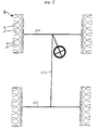
- an alternative embodiment of the present invention shown in Figure 3 may be employed.
- the tyre 3 has two patterns of tread grooves, one pattern of grooves 4 and another pattern of grooves 5 which curve in opposite circumferential direction as they progress axially inwardly. Whilst only the pattern of grooves 4 will have the optimum alignment for braking and the pattern of grooves 5 will have the optimum alignment for acceleration, overall the combination of grooves shown retain to a large degree the beneficial reduced tread wear attributable to the invention.
- tread grooves Whilst the aforementioned tread grooves as shown and described as continuous across the axial width of the tread they may be discontinuous in which event each groove section be it straight or curved is aligned according to the invention.
- Example of discontinuous groove patterns are shown in the schematic diagrams Figure 4 and Figure 5. Thus these discontinuous patterns comprise individual groove sections 10a-10f and lla-llf respectively.
- the tread may also comprise longitudinal tread grooves.
- the invention also provides a method of determining the required tread groove angle or alignment to form the tread pattern having optimum, i.e. minimum, tread wear. This method comprises at successive axial points across the tread from one edge to the other edge aligning the tread groove in the same direction as the resultant typical slippage of the tread when the axial point concerned is within or at the centre of the tread/road contact region.
- This method may be implemented either by calculation or by practical determination.
- the tyre preferably an unused tyre
- the tyre is provided with an array of small holes, preferably circular in shape at the tyre surface, to provide a hole at each axial position across the tread surface.
- the tyre is then run on the vehicle under all driving conditions to initiate wearing of the tread over its entire width.
- the tread wear will become apparent with the appearance of a pattern of wear emanating in a particular direction from each small hole according to the axial position of the hole.
- the tread groove pattern can be formed or cut into the tread of another tyre by aligning the tread groove at any particular axial position in the same direction as the wear pattern emanating from the hole at that position on the worn tyre.
Landscapes
- Engineering & Computer Science (AREA)
- Mechanical Engineering (AREA)
- Tires In General (AREA)
Abstract
Description
Claims (7)
- A tyre for a vehicle having at least one wheel at each corner, the tyre comprising a ground contacting tread (1) extending axially between first and second edge regions (IE,OE) and having tread grooves (2,10,11) formed therein, characterised in that in the first axial edge region (IE) of the tread the tread grooves are aligned substantially in the tyre circumferential direction and in the second axial edge region (OE) of the tread the grooves are aligned substantially in the tyre axial direction and in a third axial region (CR) of the tread axially between the first (IE) and second edge (OE) regions the alignment of the grooves changes progressively from circumferential to axial.
- A tyre according to claim 1, characterised in that the grooves (2) extend continuously from the first axial edge region (IE) to the second axial edge region (OE).
- A tyre mounted on a vehicle, the tyre comprising a ground contacting tread (1) extending between first and second axial edge regions(IE,OE) and having tread grooves (2,10,11) formed therein, characterised in that the first axial edge region (IE) of the tread the tread grooves are aligned substantially in the tyre circumferential direction and in a second axial edge region (OE) of the tread the grooves are aligned substantially in the tyre axial direction and in a third axial region (CR) of the tread (1) axially between the first and second edge regions the alignment of the grooves changes progressively from circumferential to axial and the first axial edge region of the tyre is disposed nearest to the vehicle longitudinal centreline (VCL).
- A tyre mounted on a vehicle according to claim 3, characterised in that the tread grooves (2) extend continuously from the first or inner axial edge region to the second or outer axial edge region of the tyre.
- A method of determining the required tread groove angle to form the tread pattern of a tyre for a vehicle having a wheel at each corner to give optimum tread wear comprising at successive axial points across the tread from the centre to the tread edge aligning the tread groove substantially in the direction of the resultant force acting on the tread at that axial point when the point is in the tyre/road contact region.
- A method in accordance with claim 5, comprising forming small holes in the tread surface at successive axial positions across the tread from the centre to the edge, running the tyre on the vehicle to initiate a pattern of wear emanating from each small hole, and forming tread grooves in the surface of a subsequent tyre such that at any particular axial point the tread groove is aligned in the same direction as the pattern of wear emanating from the small hole formed at that point on the worn tyre.
- A method according to claim 6, wherein the small holes are circular in shape at the tyre surface.
Applications Claiming Priority (2)
| Application Number | Priority Date | Filing Date | Title |
|---|---|---|---|
| GB9720915 | 1997-10-03 | ||
| GBGB9720915.9A GB9720915D0 (en) | 1997-10-03 | 1997-10-03 | Vehicle tyre |
Publications (3)
| Publication Number | Publication Date |
|---|---|
| EP0906837A2 true EP0906837A2 (en) | 1999-04-07 |
| EP0906837A3 EP0906837A3 (en) | 2000-10-25 |
| EP0906837B1 EP0906837B1 (en) | 2004-08-25 |
Family
ID=10819942
Family Applications (1)
| Application Number | Title | Priority Date | Filing Date |
|---|---|---|---|
| EP98308055A Expired - Lifetime EP0906837B1 (en) | 1997-10-03 | 1998-10-02 | Vehicle tyre |
Country Status (5)
| Country | Link |
|---|---|
| US (2) | US6190478B1 (en) |
| EP (1) | EP0906837B1 (en) |
| JP (1) | JP4242954B2 (en) |
| DE (1) | DE69825829T2 (en) |
| GB (1) | GB9720915D0 (en) |
Cited By (1)
| Publication number | Priority date | Publication date | Assignee | Title |
|---|---|---|---|---|
| US6200401B1 (en) * | 1997-10-03 | 2001-03-13 | Sumitomo Rubber Industries, Limited | Method of determining groove angle to give optimum tread wear |
Families Citing this family (6)
| Publication number | Priority date | Publication date | Assignee | Title |
|---|---|---|---|---|
| USD473184S1 (en) | 2001-02-07 | 2003-04-15 | Michelin Recherche Et Technique, S.A. | Tire tread |
| USD456762S1 (en) | 2001-04-02 | 2002-05-07 | The Goodyear Tire & Rubber Company | Tire tread |
| JP4373815B2 (en) * | 2004-03-03 | 2009-11-25 | 株式会社ブリヂストン | Pneumatic tire |
| JP4976214B2 (en) * | 2007-06-22 | 2012-07-18 | 株式会社ブリヂストン | Pneumatic tire |
| JP6397363B2 (en) * | 2015-04-03 | 2018-09-26 | 住友ゴム工業株式会社 | tire |
| US11609098B1 (en) * | 2022-06-21 | 2023-03-21 | Ayro, Inc. | Systems and methods for vehicle environmental impact cancellation |
Family Cites Families (42)
| Publication number | Priority date | Publication date | Assignee | Title |
|---|---|---|---|---|
| NL74685C (en) * | 1935-03-13 | |||
| US2154290A (en) * | 1937-01-02 | 1939-04-11 | Charles F Snyder | Tread for pneumatic tires |
| GB1132352A (en) * | 1965-03-12 | 1968-10-30 | Dunlop Co Ltd | Improvements in or relating to pneumatic tyres |
| GB1242219A (en) * | 1967-10-18 | 1971-08-11 | Dunlop Holdings Ltd | Improvements in or relating to pneumatic tyres |
| GB1297627A (en) * | 1969-01-23 | 1972-11-29 | ||
| FR2053873A5 (en) * | 1969-07-21 | 1971-04-16 | Michelin & Cie | |
| FR2080054A5 (en) * | 1970-02-20 | 1971-11-12 | Michelin & Cie | |
| IT989044B (en) * | 1973-06-12 | 1975-05-20 | Pirelli | TIRE SUITABLE TO ALLOW HIGH GRIP AND GOOD ROAD HOLDING IN ALL RUNNING CONDITIONS |
| US3929179A (en) * | 1973-12-05 | 1975-12-30 | Kennametal Inc | Indicator device for indicating tread wear and tire incorporating the indicator |
| DE2455130A1 (en) * | 1974-11-21 | 1976-05-26 | Continental Gummi Werke Ag | PNEUMATIC TIRES FOR MOTOR VEHICLES |
| JPS5522535A (en) * | 1978-08-04 | 1980-02-18 | Bridgestone Corp | Heavy vehicle pneumatic tire |
| JPS6198601A (en) * | 1984-10-22 | 1986-05-16 | Yokohama Rubber Co Ltd:The | Pneumatic tire |
| JPS61139502A (en) * | 1984-12-11 | 1986-06-26 | Bridgestone Corp | Pneumatic tyre |
| JPS62146704A (en) * | 1985-12-23 | 1987-06-30 | Yokohama Rubber Co Ltd:The | Pneumatic tire |
| JPS63106114A (en) * | 1986-06-13 | 1988-05-11 | Bridgestone Corp | Pneumatic tyre |
| GB2192842B (en) * | 1986-06-13 | 1991-01-30 | Bridgestone Corp | Pneumatic tire |
| JPS63222907A (en) * | 1987-03-11 | 1988-09-16 | Bridgestone Corp | Pneumatic tire |
| DE3726593C2 (en) * | 1987-03-11 | 1994-08-04 | Bridgestone Corp | tire |
| JPH07115570B2 (en) * | 1987-03-11 | 1995-12-13 | 株式会社ブリヂストン | Pneumatic tire |
| JPS6452507A (en) * | 1987-05-08 | 1989-02-28 | Bridgestone Corp | Pneumatic tire pair |
| JPH01262204A (en) * | 1988-04-14 | 1989-10-19 | Bridgestone Corp | Pneumatic tire |
| US4984616A (en) * | 1989-05-25 | 1991-01-15 | The Goodyear Tire & Rubber Company | Front and rear tire tread patterns in a four-wheeled tire/vehicle system |
| JPH03104709A (en) * | 1989-09-19 | 1991-05-01 | Bridgestone Corp | Pneumatic tire |
| JPH03143706A (en) * | 1989-10-30 | 1991-06-19 | Yokohama Rubber Co Ltd:The | Mounting method for pneumatic tire |
| US5027876A (en) * | 1989-11-13 | 1991-07-02 | The Goodyear Tire & Rubber Company | Environmental tire |
| JP2857493B2 (en) * | 1990-11-30 | 1999-02-17 | 住友ゴム工業 株式会社 | Pneumatic tire |
| JP3104709B2 (en) | 1991-01-31 | 2000-10-30 | 株式会社島津製作所 | MR imaging device |
| USD340893S (en) * | 1991-10-14 | 1993-11-02 | Bridgestone Corporation | Automobile tire |
| USD340899S (en) * | 1991-10-14 | 1993-11-02 | Bridgestone Corporation | Automobile tire |
| JPH05178023A (en) * | 1991-12-27 | 1993-07-20 | Yokohama Rubber Co Ltd:The | Pneumatic tire |
| JP3229373B2 (en) * | 1992-07-09 | 2001-11-19 | 横浜ゴム株式会社 | Pneumatic tire |
| EP0599566B1 (en) * | 1992-11-20 | 1996-08-14 | Sumitomo Rubber Industries Limited | Method of selecting a tyre tread pattern for preventing vehicle skew |
| IT1265035B1 (en) * | 1993-05-31 | 1996-10-28 | Pirelli | TIRE FOR VEHICLE WHEELS WITH LOW ROLLING NOISE TREAD |
| JP2606773Y2 (en) * | 1993-09-30 | 2001-01-09 | 弘 都築 | Vehicle tires |
| JP2899204B2 (en) * | 1994-03-09 | 1999-06-02 | 住友ゴム工業株式会社 | Pneumatic tire arrangement structure for four-wheel vehicles |
| JPH08104109A (en) * | 1994-10-06 | 1996-04-23 | Bridgestone Corp | Pneumatic tire |
| JP3643152B2 (en) * | 1995-10-24 | 2005-04-27 | 株式会社ブリヂストン | Pneumatic tire for motorcycle |
| JP3513340B2 (en) * | 1995-12-05 | 2004-03-31 | 住友ゴム工業株式会社 | Pneumatic tires for vehicles |
| FR2748696B1 (en) * | 1996-05-20 | 1999-12-31 | Bridgestone Corp | PNEUMATIC TAPE WITH ASYMMETRICAL DIRECTIONAL DESIGN IN PARTICULAR FOR A RACE CAR |
| US5980668A (en) * | 1996-06-10 | 1999-11-09 | Kumho & Co, Inc | Tire with rotation time tread wear indicator |
| JP3243427B2 (en) * | 1997-03-07 | 2002-01-07 | 住友ゴム工業株式会社 | Motorcycle tires |
| GB9720914D0 (en) * | 1997-10-03 | 1997-12-03 | Sumitomo Rubber Ind | Tyre for a two-wheeled vehicle |
-
1997
- 1997-10-03 GB GBGB9720915.9A patent/GB9720915D0/en not_active Ceased
-
1998
- 1998-09-29 JP JP27571298A patent/JP4242954B2/en not_active Expired - Fee Related
- 1998-10-01 US US09/164,773 patent/US6190478B1/en not_active Expired - Fee Related
- 1998-10-02 EP EP98308055A patent/EP0906837B1/en not_active Expired - Lifetime
- 1998-10-02 DE DE69825829T patent/DE69825829T2/en not_active Expired - Lifetime
-
2000
- 2000-09-25 US US09/668,155 patent/US6523588B1/en not_active Expired - Fee Related
Cited By (1)
| Publication number | Priority date | Publication date | Assignee | Title |
|---|---|---|---|---|
| US6200401B1 (en) * | 1997-10-03 | 2001-03-13 | Sumitomo Rubber Industries, Limited | Method of determining groove angle to give optimum tread wear |
Also Published As
| Publication number | Publication date |
|---|---|
| EP0906837A3 (en) | 2000-10-25 |
| JP4242954B2 (en) | 2009-03-25 |
| US6190478B1 (en) | 2001-02-20 |
| GB9720915D0 (en) | 1997-12-03 |
| DE69825829T2 (en) | 2005-09-01 |
| JPH11165506A (en) | 1999-06-22 |
| DE69825829D1 (en) | 2004-09-30 |
| US6523588B1 (en) | 2003-02-25 |
| EP0906837B1 (en) | 2004-08-25 |
Similar Documents
| Publication | Publication Date | Title |
|---|---|---|
| EP0678402B1 (en) | A tread for a tire | |
| JP3599809B2 (en) | Tread band for tires for medium / heavy load vehicles | |
| JP3177466B2 (en) | Pneumatic tire | |
| EP1992503B1 (en) | Pneumatic tire with asymmetric tread pattern | |
| JPH0547405B2 (en) | ||
| WO2017039679A1 (en) | Truck tire tread and truck tire | |
| US6200401B1 (en) | Method of determining groove angle to give optimum tread wear | |
| JP2002029224A (en) | Pneumatic tire | |
| EP1093939B1 (en) | An on/off road tread for a tire | |
| JPS61222806A (en) | Improvements in wheel driving car and radial-ply tire thereof | |
| EP2316665B1 (en) | Pneumatic tire | |
| JPH0891023A (en) | Radial tire for taxi | |
| JPS62103205A (en) | Heavy load pneumatic tyre | |
| CA2589272A1 (en) | On/off-road tire for a motor vehicle | |
| EP0906837B1 (en) | Vehicle tyre | |
| JP2019156025A (en) | tire | |
| EP2316664B1 (en) | Pneumatic tire | |
| EP3670209B1 (en) | Tread for a pneumatic tire | |
| US4240484A (en) | Pneumatic tire for large size and high speed motor cycles two-wheeled vehicles | |
| CN113524986A (en) | Tyre for vehicle wheels | |
| CN112046205A (en) | Tyre for vehicle wheels | |
| JP3901830B2 (en) | Pneumatic radial tires for rear-wheel drive passenger cars | |
| EP1304239A2 (en) | Tread pattern for a heavy duty tire | |
| JPH02179509A (en) | Pneumatic tire | |
| JPH10278511A (en) | High performance pneumatic radial tire for passenger car |
Legal Events
| Date | Code | Title | Description |
|---|---|---|---|
| PUAI | Public reference made under article 153(3) epc to a published international application that has entered the european phase |
Free format text: ORIGINAL CODE: 0009012 |
|
| AK | Designated contracting states |
Kind code of ref document: A2 Designated state(s): DE FR GB |
|
| AX | Request for extension of the european patent |
Free format text: AL;LT;LV;MK;RO;SI |
|
| PUAL | Search report despatched |
Free format text: ORIGINAL CODE: 0009013 |
|
| AK | Designated contracting states |
Kind code of ref document: A3 Designated state(s): AT BE CH CY DE DK ES FI FR GB GR IE IT LI LU MC NL PT SE |
|
| AX | Request for extension of the european patent |
Free format text: AL;LT;LV;MK;RO;SI |
|
| RIC1 | Information provided on ipc code assigned before grant |
Free format text: 7B 60C 11/03 A, 7B 60C 19/00 B, 7B 60C 11/24 B, 7B 60C 111:00 Z |
|
| 17P | Request for examination filed |
Effective date: 20010410 |
|
| AKX | Designation fees paid |
Free format text: DE FR GB |
|
| 17Q | First examination report despatched |
Effective date: 20030304 |
|
| GRAP | Despatch of communication of intention to grant a patent |
Free format text: ORIGINAL CODE: EPIDOSNIGR1 |
|
| GRAS | Grant fee paid |
Free format text: ORIGINAL CODE: EPIDOSNIGR3 |
|
| GRAA | (expected) grant |
Free format text: ORIGINAL CODE: 0009210 |
|
| AK | Designated contracting states |
Kind code of ref document: B1 Designated state(s): DE FR GB |
|
| REG | Reference to a national code |
Ref country code: GB Ref legal event code: FG4D |
|
| REF | Corresponds to: |
Ref document number: 69825829 Country of ref document: DE Date of ref document: 20040930 Kind code of ref document: P |
|
| PLBE | No opposition filed within time limit |
Free format text: ORIGINAL CODE: 0009261 |
|
| STAA | Information on the status of an ep patent application or granted ep patent |
Free format text: STATUS: NO OPPOSITION FILED WITHIN TIME LIMIT |
|
| ET | Fr: translation filed | ||
| 26N | No opposition filed |
Effective date: 20050526 |
|
| PGFP | Annual fee paid to national office [announced via postgrant information from national office to epo] |
Ref country code: GB Payment date: 20100929 Year of fee payment: 13 |
|
| PGFP | Annual fee paid to national office [announced via postgrant information from national office to epo] |
Ref country code: FR Payment date: 20101020 Year of fee payment: 13 |
|
| PGFP | Annual fee paid to national office [announced via postgrant information from national office to epo] |
Ref country code: DE Payment date: 20100929 Year of fee payment: 13 |
|
| GBPC | Gb: european patent ceased through non-payment of renewal fee |
Effective date: 20111002 |
|
| REG | Reference to a national code |
Ref country code: FR Ref legal event code: ST Effective date: 20120629 |
|
| PG25 | Lapsed in a contracting state [announced via postgrant information from national office to epo] |
Ref country code: DE Free format text: LAPSE BECAUSE OF NON-PAYMENT OF DUE FEES Effective date: 20120501 |
|
| REG | Reference to a national code |
Ref country code: DE Ref legal event code: R119 Ref document number: 69825829 Country of ref document: DE Effective date: 20120501 |
|
| PG25 | Lapsed in a contracting state [announced via postgrant information from national office to epo] |
Ref country code: GB Free format text: LAPSE BECAUSE OF NON-PAYMENT OF DUE FEES Effective date: 20111002 Ref country code: FR Free format text: LAPSE BECAUSE OF NON-PAYMENT OF DUE FEES Effective date: 20111102 |