EP0906793B1 - Arrangement for positioning flat objects - Google Patents
Arrangement for positioning flat objects Download PDFInfo
- Publication number
- EP0906793B1 EP0906793B1 EP98114656A EP98114656A EP0906793B1 EP 0906793 B1 EP0906793 B1 EP 0906793B1 EP 98114656 A EP98114656 A EP 98114656A EP 98114656 A EP98114656 A EP 98114656A EP 0906793 B1 EP0906793 B1 EP 0906793B1
- Authority
- EP
- European Patent Office
- Prior art keywords
- rigid body
- container
- arrangement according
- article
- articles
- Prior art date
- Legal status (The legal status is an assumption and is not a legal conclusion. Google has not performed a legal analysis and makes no representation as to the accuracy of the status listed.)
- Expired - Lifetime
Links
- 238000013016 damping Methods 0.000 claims description 5
- 230000006378 damage Effects 0.000 description 3
- 238000000034 method Methods 0.000 description 3
- 230000005484 gravity Effects 0.000 description 2
- 239000004809 Teflon Substances 0.000 description 1
- 229920006362 Teflon® Polymers 0.000 description 1
- 238000010073 coating (rubber) Methods 0.000 description 1
- 239000011248 coating agent Substances 0.000 description 1
- 238000000576 coating method Methods 0.000 description 1
- 230000002349 favourable effect Effects 0.000 description 1
- 230000002265 prevention Effects 0.000 description 1
- 230000000284 resting effect Effects 0.000 description 1
- 230000008093 supporting effect Effects 0.000 description 1
Images
Classifications
-
- B—PERFORMING OPERATIONS; TRANSPORTING
- B65—CONVEYING; PACKING; STORING; HANDLING THIN OR FILAMENTARY MATERIAL
- B65H—HANDLING THIN OR FILAMENTARY MATERIAL, e.g. SHEETS, WEBS, CABLES
- B65H29/00—Delivering or advancing articles from machines; Advancing articles to or into piles
- B65H29/68—Reducing the speed of articles as they advance
Definitions
- the invention relates to an arrangement for positioning flat objects in the container with straight sides be transported.
- the invention specified in claim 1 is the problem based on flat objects of different masses and Thickness during the transportation process at high speed in a container with straight sides by prevention an uncontrolled backward movement of the objects as a result Bouncing off to bring the flapper gently into a certain end position.
- the force acting against a limit generated by a spring element acting on the rigid body engages according to claim 3 to the rigid body, an attenuator on.
- the baffle plate Execute container so that the kinetic energy of the flat Objects is at least reduced.
- the pivoting range of the rigid body by means of a stop to limit so that the very light, thin and sensitive Objects with the help of an advantageous guide Claim 9 directly without touching the rigid body Baffle plate.
- the baffle plate is according to claim 7 so designed that the kinetic energy of these light objects is approximately neutralized.
- the baffle plate has according to claim 8, an elastic surface and / or a sprung and cushioned storage.
- the container with to provide a lateral recess through which the on the Loading station permanently installed rigid body and if necessary the Project the guiding device into the container so that it can pivot.
- each for a stacking compartment provided guide device that the objects in guides the stacking compartment, a rigid body pivoted so that when moving backwards a clamping of the object he follows. This makes it clean for further processing Batch image reached.
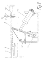
- the flat objects 6 are horizontal in FIG 1 from the left through a transport system upright at high speed a laterally open, locally fixed container 1 transported.
- the flat objects 6 are braked in this container 1 and aligned. Then the objects 6 fall braked via an opening mechanism in the bottom of the container 1 in shipping containers, the objects 6 horizontally, however Transport into container 1 perpendicular to the movement.
- the range of variation of the objects is relatively large. she ranges from thin, sensitive letters to compact packages with magazines.
- a Spring damping mechanism 10 attached to the bouncing Item 6 causes the baffle 7 damped springs back.
- This movable baffle 7 with the spring damping mechanism 10 was dimensioned so that the light letters be braked without damage, without any significant Rebound movement takes place.
- the thicker and heavier objects 6 hit the rigid body 2 and push it against the force of the damped Spring element 11 to the side so that the object to the flapper arrives.
- the rigid body 2 touches the object 6 its long side and presses it against the closed long side of container 1 or against one already in container 1 located object. The damping makes unwanted Avoided vibrations.
- the object bounces against the baffle plate 7 due to its Kinetic energy back, so it becomes between the rigid body 2 and the container wall or the already existing object trapped due to self-locking.
- the location of the pivot bearing 3 the length of the rigid body 2 and the swivel range selected so that during transport in the Container 1 the points of contact between object 6 and stare Body 2 always behind the pivot bearing 3 in the transport direction and when moving backward, the point of contact between rigid body 2 and object 6 in front of the pivot bearing 3 lies backwards in the transport direction.
- the rigid body 2 on the loading opening of the container 1 facing One side with a Teflon coating and one with the clamp effective side a rubber coating.
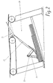
- FIG. 2 shows stacking compartments 20 of a mail item sorting machine shown in a side view.
- the shipments in the respective Stacking tray 20 passed.
- the baffles 22 are on the Stack up and thus approach more and more a horizontal one Position, the fuller the stacking bin 20 is. So the shipments assume a defined stacking position in the stacking compartment 20 and Backward movements are avoided on the shipments opposite side of the guide plates 22, a support 23 is attached.
- a rigid body 24 is pivotable at the end of this support 23 attached by a slot in the baffle 22 through his Gravity rests on the top shipment.
Landscapes
- Engineering & Computer Science (AREA)
- Mechanical Engineering (AREA)
- Pile Receivers (AREA)
- Details Of Rigid Or Semi-Rigid Containers (AREA)
- Attitude Control For Articles On Conveyors (AREA)
Description
Die Erfindung betrifft eine Anordnung zum Positionieren von flachen Gegenständen, die im Behälter mit geraden Seiten transportiert werden.The invention relates to an arrangement for positioning flat objects in the container with straight sides be transported.
Bei der Sortierung und Förderung flacher Gegenstände gelangen diese mit hoher Geschwindigkeit in den Behälter. Dabei müssen die Gegenstände abgebremst werden. Dieses trifft auf die Sortierung der Gegenstände, z.B. Briefe und Großbriefe, in die Sortierfächer und auf die Übergabe der Gegenstände in Behälter beim Wechsel des Förderprinzips, z.B. vom Längs- zum Quertransport zu.When sorting and conveying flat objects into the container at high speed. Doing so the objects are slowed down. This applies to the sorting the objects, e.g. Letters and large letters in which Sorting bins and the transfer of items to containers when changing the funding principle, e.g. from longitudinal to Cross transport too.
Es wurde eine Lösung bekannt, bei der in einem Zwischenspeicher die Gegenstände horizontal in eine Tasche als Behälter gelangen (DE 196 24 968.6). Zum Abbremsen und Positionieren befinden sich bei diesem Vorgang federnde schräge Bleche in der Tasche, wodurch die Gegenstände abgebremst und eingeklemmt werden. Dabei sind die Gegenstände hohen mechanischen Belastungen ausgesetzt, was bei empfindlichen Gegenständen zur Zerstörung führen kann. Da die Gegenstände unterschiedliche Dicke und Masse aufweisen können, ist deren ausgerichtete Lage in der Tasche nicht möglich. Das Vorsehen eines Absatzes in dem Blech zur Fixierung der Lage beansprucht die Gegenstände zu stark, da die Bewegungsenergie dämpfungslos sofort vernichtet werden muss.A solution has been known in which in a buffer the objects horizontally in a pocket as a container arrive (DE 196 24 968.6). For braking and positioning are resilient sloping plates in this process the bag, causing the objects to slow down and get trapped become. The objects are high mechanical Exposed to what is sensitive objects can lead to destruction. Because the items are different Can have thickness and mass is their aligned Can not be in your pocket. The provision of a paragraph in the sheet for fixing the position strained the objects too strong because the kinetic energy is damped immediately must be destroyed.
Es wurden auch Lösungen bekannt, bei denen flache Gegenstände,
wie Sendungen oder Formulare, in Stapelfächer, die in
Transportrichtung eine Prallwand aufweisen, gelangen
(EP-A-0270731, US-A-3124352).
Die Stapelfächer weisen Bügel zum Leiten der Gegenstände in
die Behälter auf, die in Transportrichtung zum Behälterboden
hin geneigt sind und infolge Schwerkraft auf dem obersten
Gegenstand aufliegen. Einzelne einzustapelnde Blätter oder
dünne Sendungen verlieren an der Prallwand weitgehend ihre
Bewegungsenergie und bleiben daher an ihr liegen, wobei die
Reibkräfte des aufliegenden Bügels gegebenenfalls unterstützend
wirken.
Große und schwere Sendungen würden aber zurückprallen.Solutions have also been known in which flat objects, such as mail items or forms, get into stacking compartments which have a baffle in the direction of transport (EP-A-0270731, US-A-3124352).
The stacking compartments have brackets for guiding the objects into the containers, which are inclined in the transport direction towards the container bottom and rest on the uppermost object due to gravity. Individual sheets or thin consignments to be stacked largely lose their kinetic energy on the baffle and therefore remain there, the frictional forces of the bracket resting on them possibly having a supporting effect.
Large and heavy shipments would bounce back.
Der im Anspruch 1 angegebenen Erfindung liegt das Problem zugrunde, flache Gegenstände unterschiedlicher Masse und Dicke im Laufe des Transportvorganges mit hoher Geschwindigkeit in einen Behälter mit geraden Seiten durch Verhinderung einer unkontrollierten Rückwärtsbewegung der Gegenstände infolge Abprallens an der Prallplatte schonend in eine bestimmte Endposition zu bringen.The invention specified in claim 1 is the problem based on flat objects of different masses and Thickness during the transportation process at high speed in a container with straight sides by prevention an uncontrolled backward movement of the objects as a result Bouncing off to bring the flapper gently into a certain end position.
Durch den in Richtung der Ein- und Ausschleusbewegung der Gegenstände in den Behälter schwenkbaren starren Körper und die Wahl des Schwenklagerortes - Berührungspunkt zwischen starrem Körper und jeweils in den Behälter transportierten Gegenstand liegt bei evtl. Rückwärtsbewegung stets vor dem Schwenklager - wird der Gegenstand relativ unabhängig von seiner Dicke und Masse bei einer Rückwärtsbewegung sicher eingeklemmt, wobei die Rückwärtsbewegung nur einen kleinen definierten Weg beinhaltet.By moving the objects in and out rigid body pivoting into the container and the choice of the swivel bearing location - point of contact between the rigid body and each item transported in the container is included possible backward movement always in front of the swivel bearing - the Item relatively regardless of its thickness and mass a backward movement securely pinched, the backward movement contains only a small defined path.
In den Unteransprüchen sind weitere vorteilhafte Ausführungen angegeben.Further advantageous embodiments are in the subclaims specified.
Gemäß Anspruch 2 wird die gegen eine Begrenzung wirkende Kraft
durch ein am starren Körper angreifendes Federelement erzeugt.
Um ungewollte Schwingungen des starren Körpers zu vermeiden,
greift nach Anspruch 3 an den starren Körper ein Dämpfungsglied
an.According to
Nach Anspruch 4 ist es vorteilhaft, zur Unterstützung des Gleitens der Gegenstände am starren Körper bei der Bewegung der Gegenstände in den Behälter und zur Unterstützung des Festhaltens bei der Rückwärtsbewegung den starren Körper mit unterschiedlichen Reibkoeffizienten auszustatten.According to claim 4, it is advantageous to support the sliding the objects on the rigid body when moving the Objects in the container and to help hold on when moving backwards the rigid body with different Equip coefficient of friction.
Vorteilhaft ist es auch, gemäß Anspruch 5 die Prallplatte des Behälters so auszuführen, daß die Bewegungsenergie der flachen Gegenstände zumindest reduziert wird.It is also advantageous, according to claim 5, the baffle plate Execute container so that the kinetic energy of the flat Objects is at least reduced.
Sollen Gegenstände in einem sehr großen Dicken- und Massenbereich
verarbeitet werden, so ist es günstig, gemäß Anspruch 6
den Schwenkbereich des starren Körpers mittels eines Anschlages
so zu begrenzen, daß die sehr leichten, dünnen und empfindlichen
Gegenstände mit Hilfe einer vorteilhaften Leiteinrichtung nach
Anspruch 9 direkt ohne Berührung mit dem starren Körper zur
Prallplatte gelangen. Die Prallplatte ist dabei gemäß Anspruch 7
so ausgeführt, daß die Bewegungsenergie dieser leichten Gegenstände
annähernd neutralisiert wird. Dafür hat die Prallplatte
nach Anspruch 8 eine elastische Oberfläche und/oder eine gefederte
und gedämpfte Lagerung.Are objects in a very large range of thicknesses and masses
are processed, it is favorable, according to claim 6
the pivoting range of the rigid body by means of a stop
to limit so that the very light, thin and sensitive
Objects with the help of an
Bei beweglichen Behältern, die an einem bestimmten Ort beladen
werden, ist es nach Anspruch 11 vorteilhaft, die Behälter mit
einer seitlichen Ausnehmung zu versehen, durch welche der an der
Beladestation fest installierte starre Körper und bei Bedarf die
Leitvorrichtung in die Behälter schwenkbar hineinragen.For moving containers that are loaded at a specific location
be, it is advantageous according to
Wird die Anordnung für Stapelfächer von Sortiermaschinen verwendet,
so wird gemäß Anspruch 12 an jeder für jeweils ein Stapelfach
vorgesehenen Führungseinrichtung, die die Gegenstände in
das Stapelfach leitet, ein starrer Körper schwenkbar so angebracht,
daß bei Rückwärtsbewegung eine Klemmung des Gegenstandes
erfolgt. Damit wird ein für eine weitere Verarbeitung sauberes
Stapelbild erreicht.If the arrangement is used for stacking compartments of sorting machines,
so according to
Anschließend wird die Erfindung an Ausführungsbeispielen näher erläutert. Dabei zeigen:
- FIG 1
- eine schematische Draufsicht auf einen Behälter zur Aufnahme eines flachen Gegenstandes an einer Beladestation
- FIG 2
- eine schematische Seitenansicht eines Stapelfaches einer Sortiermaschine
- FIG. 1
- is a schematic plan view of a container for receiving a flat object at a loading station
- FIG 2
- is a schematic side view of a stacking compartment of a sorting machine
Die flachen Gegenstände 6 werden in FIG 1 horizontal von links
über ein Transportsystem aufrecht mit hoher Geschwindigkeit in
einen seitlich offenen, örtlich festen Behälter 1 transportiert. The
In diesem Behälter 1 werden die flachen Gegenstände 6 abgebremst
und ausgerichtet. Anschließend fallen die Gegenstände 6 abgebremst
über einen Öffnungsmechanismus im Boden des Behälters 1
in Transportbehälter, die die Gegenstände 6 horizontal, aber
senkrecht zur Bewegung in den Behälter 1 abtransportieren.The
Die Variationsbreite der Gegenstände ist relativ groß. Sie
reicht von dünnen, empfindlichen Briefen bis zu kompakten Päckchen
mit Zeitschriften. Am Ende des Behälters 1 treffen die
Gegenstände zur Verminderung bzw. Beseitigung der Bewegungsenergie
auf eine Prallplatte 7 mit einer elastischen Oberfläche 9,
die in einem Drehpunkt 8, der sich seitlich vom Behälter 1
befindet, gelagert ist. An der Prallplatte 7 ist weiterhin ein
Feder-Dämpfungs-Mechanismus 10 befestigt, der bei einem aufprallenden
Gegenstand 6 bewirkt, daß die Prallplatte 7 gedämpft
zurückfedert.The range of variation of the objects is relatively large. she
ranges from thin, sensitive letters to compact packages
with magazines. At the end of the container 1 meet
Objects for reducing or eliminating kinetic energy
onto a baffle plate 7 with an
Diese bewegliche Prallplatte 7 mit dem Feder-Dämpfungs-Mechanismus
10 wurde so dimensioniert, daß die leichten Briefe
beschädigungsfrei abgebremst werden, ohne daß dabei eine nennenswerte
Rückprallbewegung stattfindet. Die dickeren, schwereren
und stabileren Gegenstände 6 werden durch den nachfolgend
beschriebenen erfindungsgemäßen Mechanismus an einer größeren
Rückwärtsbewegung gehindert.This movable baffle 7 with the
Dabei ist an einem Schwenklager 3 ein gerader Flachkörper als
starrer Körper 2 gelagert. Durch eine Aussparung in dem Behälter
1 ragt er in diesen hinein. An den starren Körper 2 greift ein
Federelement 11 mit einem Dämpfungsglied an und drückt den
starren Körper 2 entgegen der Transportrichtung der Gegenstände
6 in den Behälter 1 an einen Anschlag 12. Dieser begrenzt den
Schwenkbereich des starren Körpers 2 so, daß ein Spalt für die
empfindlichen, dünnen Briefe freibleibt und eine Beschädigung am
starren Körper 2 verhindert wird. Damit die Briefe ungehindert
durch diesen Spalt gelangen, ist in Transportrichtung vor dem
starren Körper 2 eine schwenkbare glatte Leiteinrichtung 4
vorhanden, die ebenfalls durch die Aussparung in den Behälter 1
ragt. Die dickeren und schwereren Gegenstände 6 stoßen an den
starren Körper 2 und drücken ihn gegen die Kraft des gedämpften
Federelementes 11 zur Seite, so daß der Gegenstand zur Prallplatte
gelangt. Der starre Körper 2 berührt den Gegenstand 6 an
seiner Längsseite und drückt ihn gegen die geschlossene Längsseite
des Behälters 1 oder gegen einen schon im Behälter 1
befindlichen Gegenstand. Durch die Dämpfung werden ungewollte
Schwingungen vermieden.Here is a straight flat body on a pivot bearing 3
Prallt der Gegenstand an der Prallplatte 7 aufgrund seiner
Bewegungsenergie zurück, so wird er zwischen dem starren Körper
2 und der Behälterwand bzw. dem schon vorhandenen Gegenstand
infolge Selbsthemmung fest eingeklemmt. Damit dies geschieht,
ist der Ort des Schwenklagers 3, die Länge des starren Körpers 2
und der Schwenkbereich so gewählt, daß beim Transport in den
Behälter 1 die Berührungspunkte zwischen Gegenstand 6 und starren
Körper 2 stets hinter dem Schwenklager 3 in Transportrichtung
und bei einer Rückwärtsbewegung der Berührungspunkt zwischen
starren Körper 2 und Gegenstand 6 vor dem Schwenklager 3
in Transportrichtung rückwärts liegt.The object bounces against the baffle plate 7 due to its
Kinetic energy back, so it becomes between the
Zur Unterstützung des Gleitens bzw. des Einklemmens besitzt der
starre Körper 2 an der der Beladeöffnung des Behälters 1 zugewandten
Seite eine Teflonbeschichtung und auf der bei der Klemmung
wirksamen Seite eine Gummibeschichtung.To support the sliding or pinching, the
In der FIG 2 sind Stapelfächer 20 einer Sendungssortiermaschine
in einer Seitenansicht dargestellt. Über Weichenflügel 21 und
ein schwenkbares Leitblech 22 werden die Sendungen in das jeweilige
Stapelfach 20 geleitet. Die Leitbleche 22 liegen auf dem
Stapel auf und nähern sich also immer mehr einer waagrechten
Position, je voller das Stapelfach 20 ist. Damit die Sendungen
eine definierte Stapelposition im Stapelfach 20 einnehmen und
Rückwärtsbewegungen vermieden werden, ist an der den Sendungen
abgewandten Seite der Leitbleche 22 eine Stütze 23 befestigt. Am
Ende dieser Stütze 23 ist schwenkbar ein starrer Körper 24
angebracht, der durch einen Schlitz im Leitblech 22 durch seine
Schwerkraft auf der obersten Sendung aufliegt.2
Hier befindet sich der Schwenkpunkt des starren Körpers 24 bei
der Bewegung der Sendung in das Stapelfach 20 ebenfalls vor dem
Berührungspunkt zwischen starrem Körper 24 und oberster Sendung,
so daß bei einer Rückwärtsbewegung der obersten Sendung infolge
Abprallens an der Fachwand der beschriebene Selbstklemmvorgang
stattfindet. Here is the pivot point of the
Anordnung zum Positionieren von flachen Gegenständen
- 1
- Behälter
- 2,24
- starrer Körper
- 3
- Schwenklager
- 4
- Leiteinrichtung
- 6
- Gegenstand
- 7
- Prallplatte
- 8
- Drehpunkt
- 9
- Elastische Oberfläche
- 10
- Feder-Dämpfungs-Mechanismus
- 11
- Federelement
- 12
- Anschlag
- 20
- Stapelfach
- 21
- Weichenflügel
- 22
- Leitblech
- 23
- Stütze
- 1
- container
- 2.24
- rigid body
- 3
- pivot bearing
- 4
- guide
- 6
- object
- 7
- flapper
- 8th
- pivot point
- 9
- Elastic surface
- 10
- Spring damping mechanism
- 11
- spring element
- 12
- attack
- 20
- stacking tray
- 21
- soft wings
- 22
- baffle
- 23
- support
Claims (11)
- Arrangement for positioning flat articles (6) in a container (1) with rectilinear sides, havinga baffle plate (7), which is arranged in the region of the downstream end of the container (1) and is intended for stopping the movement of an article (6) running into the container (1), and an abutment wall of the container (1) for the abutment of a stopped article (6) by way of one flat side,a rigid body (2, 24) which can be pivoted about a pivot axis (3), located opposite the abutment wall, within an operating range, has its free end extending in an inclined manner in the transporting direction from the pivot axis (3) in the direction of the abutment wall and is forced in the direction of the abutment wall and pushed against a limiting means, it being the case that a stopped article (6) has the free end of the rigid body (2, 24) in contact with its flat side which is directed towards the pivot axis (3) and can have its flat side which is directed away from the pivot axis (3) positioned against the abutment wall of the container (1) or against an article (6) which has already been deposited, characterized in that the location of the pivot bearing (3), and the length and the pivoting range of the rigid body (2) are selected such that the articles (6) in the defined thickness range, during the rearward movement, are clamped in as a result of self-locking between the container wall, or flat articles already present in the container, and the rigid body (2).
- Arrangement according to Claim 1, characterized in that the force to which the rigid body (2) is subjected is produced by a spring element (11) acting on said rigid body.
- Arrangement according to either of Claims 1 and 2, characterized in that a damping member additionally acts on the rigid body (2).
- Arrangement according to Claim 1, characterized in that that part of the rigid body (2) which is in contact with the article (6) as it moves into the container (1) has a surface with a low coefficient of friction and the part which is in contact with the article (6) as it moves in the rearward direction has a surface with a high coefficient of friction.
- Arrangement according to Claim 1, characterized in that the baffle plate (7), in the region of the downstream end of the container (1), is configured such that it reduces the kinetic energy of the article (6).
- Arrangement according to Claim 5, characterized in that the baffle plate (7) is configured such that the kinetic energy of the articles (6) not restrained by the rigid body (2) is more or less neutralized.
- Arrangement according to Claim 5 or 6, characterized in that the baffle plate (7) has an elastic surface (9) and/or is mounted in a resilient and damped manner in the transporting direction of the articles (6).
- Arrangement according to one of Claims 5 to 7, characterized in that arranged on the rigid body (2) is a smooth directing device (4) which is pushed to a slight extent against the rigid body (2) by spring force and is intended for directing the very thin articles (6) into the gap between the abutment wall and the rigid body (2) secured by the stop (12).
- Arrangement according to Claim 1, characterized in that the operating range of the rigid body (2) is limited by the abutment wall.
- Arrangement according to Claim 1, characterized in that the containers (1) are transported and have a cutout on one side, and the rigid body (2) is fixed in location at a loading station in which the rigid body (2), and if required a directing device (4), projects in a pivotable manner through the cutout into the container (1).
- Arrangement according to Claim 1, characterized in that fastened in a bearing region of a pivotable directing plate (22), which is provided for each stacking compartment (20) of a sorting machine, directs the flat articles into the stacking compartment (20) by way of a respective diverter and rests on a stack of articles (6), is a support (23), on which the rigid body (24) is fitted in a pivotable manner such that it acts on the uppermost article (6) of the stack in the bearing region of the directing plate (22).
Applications Claiming Priority (2)
| Application Number | Priority Date | Filing Date | Title |
|---|---|---|---|
| DE19736011 | 1997-08-19 | ||
| DE19736011A DE19736011C1 (en) | 1997-08-19 | 1997-08-19 | Device for positioning flat items in container |
Publications (3)
| Publication Number | Publication Date |
|---|---|
| EP0906793A2 EP0906793A2 (en) | 1999-04-07 |
| EP0906793A3 EP0906793A3 (en) | 1999-06-02 |
| EP0906793B1 true EP0906793B1 (en) | 2002-06-26 |
Family
ID=7839477
Family Applications (1)
| Application Number | Title | Priority Date | Filing Date |
|---|---|---|---|
| EP98114656A Expired - Lifetime EP0906793B1 (en) | 1997-08-19 | 1998-08-04 | Arrangement for positioning flat objects |
Country Status (3)
| Country | Link |
|---|---|
| US (1) | US6022018A (en) |
| EP (1) | EP0906793B1 (en) |
| DE (2) | DE19736011C1 (en) |
Families Citing this family (5)
| Publication number | Priority date | Publication date | Assignee | Title |
|---|---|---|---|---|
| US6250629B1 (en) * | 1998-12-03 | 2001-06-26 | Ascom Hasler Mailing Systems, Inc. | Mailpiece stacking system and method |
| DE10043206C1 (en) * | 2000-09-01 | 2002-02-07 | Siemens Ag | Stacking device for flat items standing on their narrow sides |
| DE102005016520A1 (en) * | 2005-04-08 | 2006-10-12 | Eastman Kodak Company | Sheet depositing apparatus for sheet handling machines such as electrophotographic printing machine, has depositing surface of tray arranged at angle to horizontal |
| DE102005038622A1 (en) * | 2005-08-16 | 2007-03-01 | Siemens Ag | Alignment device for an article in a container |
| EP2481697B1 (en) * | 2011-01-28 | 2013-04-10 | Neopost Technologies | Piling device for mail items processing machine |
Family Cites Families (17)
| Publication number | Priority date | Publication date | Assignee | Title |
|---|---|---|---|---|
| GB789015A (en) * | 1955-04-19 | 1958-01-15 | British Tabulating Mach Co Ltd | Improvements in or relating to record card stacking devices |
| US2821391A (en) * | 1955-12-13 | 1958-01-28 | Bucciconi Engineering Company | Bumper pad for sheet piling mechanism |
| DE1099462B (en) * | 1959-02-23 | 1961-02-09 | Standard Elektrik Lorenz Ag | Container for holding a stack of flat objects |
| US3124352A (en) * | 1961-06-14 | 1964-03-10 | Document handling apparatus | |
| DE1181132B (en) * | 1963-03-11 | 1964-11-05 | Telefunken Patent | Device for stacking rectangular, flat mail items in a stacker |
| US4068839A (en) * | 1977-03-04 | 1978-01-17 | International Business Machines Corporation | Sheet stacking apparatus |
| DD160052A1 (en) * | 1981-06-30 | 1983-04-27 | Ulrich Hahn | FRONT EDGE BUTTON IN BOWERS OF PRINTING MACHINES |
| FR2514268A1 (en) * | 1981-10-09 | 1983-04-15 | Hotchkiss Brandt Sogeme | DEVICE FOR GUIDING AND RECEIVING LETTERS IN THE EXIT OF COURIER SORTING MACHINE AND MACHINE EQUIPPED WITH SUCH A DEVICE |
| JPS63143172A (en) * | 1986-12-03 | 1988-06-15 | Nec Corp | Stacker for sheets |
| DE3642021A1 (en) * | 1986-12-09 | 1988-06-23 | Licentia Gmbh | STACKING DEVICE FOR LETTERS |
| DE3922045C2 (en) * | 1989-07-05 | 1998-04-30 | Siemens Ag | Device for guiding and receiving flat objects such as letters |
| US5332210A (en) * | 1992-11-18 | 1994-07-26 | Pitney Bowes Inc. | Variable size envelope drop stacker having means for assuring envelope sealing |
| FR2700527B1 (en) * | 1993-01-18 | 1995-04-07 | Bertin & Cie | Device for temporary storage of flat objects. |
| US5419545A (en) * | 1994-03-10 | 1995-05-30 | Unisys Corporation | High speed document stacking assembly |
| IT1266199B1 (en) * | 1994-08-12 | 1996-12-23 | Finmeccanica Spa | DECELERATOR DEVICE FOR POSTAL OBJECTS |
| DE4444488A1 (en) * | 1994-12-14 | 1996-06-20 | Kodak Ag | Device for guiding and holding down of sheets in stack in container |
| DE19624968C1 (en) * | 1996-06-22 | 1998-01-15 | Siemens Ag | Buffer for shipments |
-
1997
- 1997-08-19 DE DE19736011A patent/DE19736011C1/en not_active Expired - Fee Related
-
1998
- 1998-08-04 DE DE59804565T patent/DE59804565D1/en not_active Expired - Fee Related
- 1998-08-04 EP EP98114656A patent/EP0906793B1/en not_active Expired - Lifetime
- 1998-08-19 US US09/136,414 patent/US6022018A/en not_active Expired - Lifetime
Also Published As
| Publication number | Publication date |
|---|---|
| EP0906793A3 (en) | 1999-06-02 |
| EP0906793A2 (en) | 1999-04-07 |
| US6022018A (en) | 2000-02-08 |
| DE19736011C1 (en) | 1998-10-15 |
| DE59804565D1 (en) | 2002-08-01 |
Similar Documents
| Publication | Publication Date | Title |
|---|---|---|
| US4089404A (en) | Tilting tray apparatus | |
| EP3577041B1 (en) | Device and method for turning, opening and filling transport bags conveyed in a suspended manner | |
| EP1592523B1 (en) | Sorting device for flat mail items | |
| US4469321A (en) | Device for the delayed piling of sheets | |
| US11780686B2 (en) | Transport container for a sorting device | |
| US3137499A (en) | Document stacking device | |
| US20180244471A1 (en) | Transport unit of an overhead conveyor system, having a buffer element | |
| DE69214824T2 (en) | CONVEYOR / STACKING MODULE FOR A POST PROCESSING SYSTEM | |
| US20090127074A1 (en) | Conveying device comprising at least one slide for piece goods, and method for stacking piece goods in a container | |
| US5324025A (en) | Physical delay buffer for paper items | |
| DE102023205635A1 (en) | Unloading station for a conveyor system, conveyor system with such an unloading station and method for the automated unloading of conveyor containers | |
| US12570482B2 (en) | Stop device for a conveyor system and a conveyer system comprising a stop device | |
| EP1663523A1 (en) | Device for filling and removing containers for sorted mail | |
| EP0906793A2 (en) | Arrangement for positioning flat objects | |
| EP1781561B1 (en) | Method and device for placing a flat freely movable object | |
| US6622851B1 (en) | Conveyor section arrangement in a filling station | |
| US5226641A (en) | Storage and stacking device for flat objects | |
| EP3450355A1 (en) | Conveying plant | |
| DE102008034179A1 (en) | Transfer device for postal items | |
| US4838539A (en) | Stacker for letters | |
| EP3305691A1 (en) | Conveying system with guide device | |
| DE10043206C1 (en) | Stacking device for flat items standing on their narrow sides | |
| DE2804043B2 (en) | Sorting bin | |
| EP0503403B1 (en) | System for sorting and for distribution of objects according to their destination and usage of the system | |
| KR20040051486A (en) | Sorting device with changeable shooting mechanism |
Legal Events
| Date | Code | Title | Description |
|---|---|---|---|
| PUAI | Public reference made under article 153(3) epc to a published international application that has entered the european phase |
Free format text: ORIGINAL CODE: 0009012 |
|
| AK | Designated contracting states |
Kind code of ref document: A2 Designated state(s): BE DE FR GB IT NL |
|
| AX | Request for extension of the european patent |
Free format text: AL;LT;LV;MK;RO;SI |
|
| PUAL | Search report despatched |
Free format text: ORIGINAL CODE: 0009013 |
|
| AK | Designated contracting states |
Kind code of ref document: A3 Designated state(s): AT BE CH CY DE DK ES FI FR GB GR IE IT LI LU MC NL PT SE |
|
| AX | Request for extension of the european patent |
Free format text: AL;LT;LV;MK;RO;SI |
|
| 17P | Request for examination filed |
Effective date: 19990706 |
|
| AKX | Designation fees paid |
Free format text: BE DE FR GB IT NL |
|
| 17Q | First examination report despatched |
Effective date: 20001120 |
|
| GRAG | Despatch of communication of intention to grant |
Free format text: ORIGINAL CODE: EPIDOS AGRA |
|
| GRAG | Despatch of communication of intention to grant |
Free format text: ORIGINAL CODE: EPIDOS AGRA |
|
| GRAH | Despatch of communication of intention to grant a patent |
Free format text: ORIGINAL CODE: EPIDOS IGRA |
|
| GRAH | Despatch of communication of intention to grant a patent |
Free format text: ORIGINAL CODE: EPIDOS IGRA |
|
| GRAA | (expected) grant |
Free format text: ORIGINAL CODE: 0009210 |
|
| AK | Designated contracting states |
Kind code of ref document: B1 Designated state(s): BE DE FR GB IT NL |
|
| REG | Reference to a national code |
Ref country code: GB Ref legal event code: FG4D Free format text: NOT ENGLISH |
|
| REF | Corresponds to: |
Ref document number: 59804565 Country of ref document: DE Date of ref document: 20020801 |
|
| GBT | Gb: translation of ep patent filed (gb section 77(6)(a)/1977) |
Effective date: 20020925 |
|
| ET | Fr: translation filed | ||
| PLBE | No opposition filed within time limit |
Free format text: ORIGINAL CODE: 0009261 |
|
| STAA | Information on the status of an ep patent application or granted ep patent |
Free format text: STATUS: NO OPPOSITION FILED WITHIN TIME LIMIT |
|
| 26N | No opposition filed |
Effective date: 20030327 |
|
| PGFP | Annual fee paid to national office [announced via postgrant information from national office to epo] |
Ref country code: GB Payment date: 20070808 Year of fee payment: 10 |
|
| PGFP | Annual fee paid to national office [announced via postgrant information from national office to epo] |
Ref country code: NL Payment date: 20070807 Year of fee payment: 10 Ref country code: IT Payment date: 20070829 Year of fee payment: 10 Ref country code: DE Payment date: 20071022 Year of fee payment: 10 Ref country code: BE Payment date: 20070813 Year of fee payment: 10 |
|
| PGFP | Annual fee paid to national office [announced via postgrant information from national office to epo] |
Ref country code: FR Payment date: 20070828 Year of fee payment: 10 |
|
| GBPC | Gb: european patent ceased through non-payment of renewal fee |
Effective date: 20080804 |
|
| NLV4 | Nl: lapsed or anulled due to non-payment of the annual fee |
Effective date: 20090301 |
|
| PG25 | Lapsed in a contracting state [announced via postgrant information from national office to epo] |
Ref country code: NL Free format text: LAPSE BECAUSE OF NON-PAYMENT OF DUE FEES Effective date: 20090301 |
|
| REG | Reference to a national code |
Ref country code: FR Ref legal event code: ST Effective date: 20090430 |
|
| PG25 | Lapsed in a contracting state [announced via postgrant information from national office to epo] |
Ref country code: BE Free format text: LAPSE BECAUSE OF NON-PAYMENT OF DUE FEES Effective date: 20080831 |
|
| PG25 | Lapsed in a contracting state [announced via postgrant information from national office to epo] |
Ref country code: IT Free format text: LAPSE BECAUSE OF NON-PAYMENT OF DUE FEES Effective date: 20080804 Ref country code: FR Free format text: LAPSE BECAUSE OF NON-PAYMENT OF DUE FEES Effective date: 20080901 Ref country code: DE Free format text: LAPSE BECAUSE OF NON-PAYMENT OF DUE FEES Effective date: 20090303 |
|
| PG25 | Lapsed in a contracting state [announced via postgrant information from national office to epo] |
Ref country code: GB Free format text: LAPSE BECAUSE OF NON-PAYMENT OF DUE FEES Effective date: 20080804 |