EP0906786B1 - Système et procédé pour embout de pulvérisation ou de production d'aérosols à écoulement unidirectionel - Google Patents
Système et procédé pour embout de pulvérisation ou de production d'aérosols à écoulement unidirectionel Download PDFInfo
- Publication number
- EP0906786B1 EP0906786B1 EP98307246A EP98307246A EP0906786B1 EP 0906786 B1 EP0906786 B1 EP 0906786B1 EP 98307246 A EP98307246 A EP 98307246A EP 98307246 A EP98307246 A EP 98307246A EP 0906786 B1 EP0906786 B1 EP 0906786B1
- Authority
- EP
- European Patent Office
- Prior art keywords
- nozzle
- flexible
- normally
- rigid shaft
- along
- Prior art date
- Legal status (The legal status is an assumption and is not a legal conclusion. Google has not performed a legal analysis and makes no representation as to the accuracy of the status listed.)
- Expired - Lifetime
Links
- 238000000034 method Methods 0.000 title claims description 11
- 239000000443 aerosol Substances 0.000 title description 23
- 239000007921 spray Substances 0.000 title description 10
- 239000007788 liquid Substances 0.000 claims description 113
- 230000007246 mechanism Effects 0.000 claims description 91
- 239000012530 fluid Substances 0.000 claims description 64
- 230000007423 decrease Effects 0.000 claims description 10
- 238000000926 separation method Methods 0.000 claims 16
- 230000005465 channeling Effects 0.000 claims 4
- 230000001939 inductive effect Effects 0.000 claims 2
- 239000004479 aerosol dispenser Substances 0.000 description 14
- 239000012080 ambient air Substances 0.000 description 11
- 239000003814 drug Substances 0.000 description 10
- 238000004519 manufacturing process Methods 0.000 description 4
- 238000011109 contamination Methods 0.000 description 3
- 239000003755 preservative agent Substances 0.000 description 3
- KAKZBPTYRLMSJV-UHFFFAOYSA-N Butadiene Chemical compound C=CC=C KAKZBPTYRLMSJV-UHFFFAOYSA-N 0.000 description 2
- 230000001580 bacterial effect Effects 0.000 description 2
- 239000000356 contaminant Substances 0.000 description 2
- 230000003247 decreasing effect Effects 0.000 description 2
- 239000000463 material Substances 0.000 description 2
- -1 polyethylene styrene Polymers 0.000 description 2
- 239000003380 propellant Substances 0.000 description 2
- CBENFWSGALASAD-UHFFFAOYSA-N Ozone Chemical compound [O-][O+]=O CBENFWSGALASAD-UHFFFAOYSA-N 0.000 description 1
- 239000004698 Polyethylene Substances 0.000 description 1
- 230000002301 combined effect Effects 0.000 description 1
- 230000001419 dependent effect Effects 0.000 description 1
- 238000007599 discharging Methods 0.000 description 1
- 230000000694 effects Effects 0.000 description 1
- 239000013013 elastic material Substances 0.000 description 1
- 230000004048 modification Effects 0.000 description 1
- 238000012986 modification Methods 0.000 description 1
- 230000002085 persistent effect Effects 0.000 description 1
- 239000004033 plastic Substances 0.000 description 1
- 229920003023 plastic Polymers 0.000 description 1
- 229920000573 polyethylene Polymers 0.000 description 1
- 229920002635 polyurethane Polymers 0.000 description 1
- 239000004814 polyurethane Substances 0.000 description 1
- 230000002265 prevention Effects 0.000 description 1
- 229920002725 thermoplastic elastomer Polymers 0.000 description 1
- 230000001988 toxicity Effects 0.000 description 1
- 231100000419 toxicity Toxicity 0.000 description 1
Images


Classifications
-
- B—PERFORMING OPERATIONS; TRANSPORTING
- B65—CONVEYING; PACKING; STORING; HANDLING THIN OR FILAMENTARY MATERIAL
- B65D—CONTAINERS FOR STORAGE OR TRANSPORT OF ARTICLES OR MATERIALS, e.g. BAGS, BARRELS, BOTTLES, BOXES, CANS, CARTONS, CRATES, DRUMS, JARS, TANKS, HOPPERS, FORWARDING CONTAINERS; ACCESSORIES, CLOSURES, OR FITTINGS THEREFOR; PACKAGING ELEMENTS; PACKAGES
- B65D83/00—Containers or packages with special means for dispensing contents
- B65D83/14—Containers for dispensing liquid or semi-liquid contents by internal gaseous pressure, i.e. aerosol containers comprising propellant
- B65D83/28—Nozzles, nozzle fittings or accessories specially adapted therefor
-
- B—PERFORMING OPERATIONS; TRANSPORTING
- B05—SPRAYING OR ATOMISING IN GENERAL; APPLYING FLUENT MATERIALS TO SURFACES, IN GENERAL
- B05B—SPRAYING APPARATUS; ATOMISING APPARATUS; NOZZLES
- B05B11/00—Single-unit hand-held apparatus in which flow of contents is produced by the muscular force of the operator at the moment of use
- B05B11/0005—Components or details
- B05B11/0062—Outlet valves actuated by the pressure of the fluid to be sprayed
- B05B11/007—Outlet valves actuated by the pressure of the fluid to be sprayed being opened by deformation of a sealing element made of resiliently deformable material, e.g. flaps, skirts, duck-bill valves
-
- B—PERFORMING OPERATIONS; TRANSPORTING
- B05—SPRAYING OR ATOMISING IN GENERAL; APPLYING FLUENT MATERIALS TO SURFACES, IN GENERAL
- B05B—SPRAYING APPARATUS; ATOMISING APPARATUS; NOZZLES
- B05B1/00—Nozzles, spray heads or other outlets, with or without auxiliary devices such as valves, heating means
- B05B1/34—Nozzles, spray heads or other outlets, with or without auxiliary devices such as valves, heating means designed to influence the nature of flow of the liquid or other fluent material, e.g. to produce swirl
- B05B1/3405—Nozzles, spray heads or other outlets, with or without auxiliary devices such as valves, heating means designed to influence the nature of flow of the liquid or other fluent material, e.g. to produce swirl to produce swirl
- B05B1/341—Nozzles, spray heads or other outlets, with or without auxiliary devices such as valves, heating means designed to influence the nature of flow of the liquid or other fluent material, e.g. to produce swirl to produce swirl before discharging the liquid or other fluent material, e.g. in a swirl chamber upstream the spray outlet
- B05B1/3421—Nozzles, spray heads or other outlets, with or without auxiliary devices such as valves, heating means designed to influence the nature of flow of the liquid or other fluent material, e.g. to produce swirl to produce swirl before discharging the liquid or other fluent material, e.g. in a swirl chamber upstream the spray outlet with channels emerging substantially tangentially in the swirl chamber
- B05B1/3431—Nozzles, spray heads or other outlets, with or without auxiliary devices such as valves, heating means designed to influence the nature of flow of the liquid or other fluent material, e.g. to produce swirl to produce swirl before discharging the liquid or other fluent material, e.g. in a swirl chamber upstream the spray outlet with channels emerging substantially tangentially in the swirl chamber the channels being formed at the interface of cooperating elements, e.g. by means of grooves
- B05B1/3436—Nozzles, spray heads or other outlets, with or without auxiliary devices such as valves, heating means designed to influence the nature of flow of the liquid or other fluent material, e.g. to produce swirl to produce swirl before discharging the liquid or other fluent material, e.g. in a swirl chamber upstream the spray outlet with channels emerging substantially tangentially in the swirl chamber the channels being formed at the interface of cooperating elements, e.g. by means of grooves the interface being a plane perpendicular to the outlet axis
-
- B—PERFORMING OPERATIONS; TRANSPORTING
- B05—SPRAYING OR ATOMISING IN GENERAL; APPLYING FLUENT MATERIALS TO SURFACES, IN GENERAL
- B05B—SPRAYING APPARATUS; ATOMISING APPARATUS; NOZZLES
- B05B11/00—Single-unit hand-held apparatus in which flow of contents is produced by the muscular force of the operator at the moment of use
- B05B11/0005—Components or details
- B05B11/0062—Outlet valves actuated by the pressure of the fluid to be sprayed
- B05B11/0072—A valve member forming part of an outlet opening
-
- B—PERFORMING OPERATIONS; TRANSPORTING
- B05—SPRAYING OR ATOMISING IN GENERAL; APPLYING FLUENT MATERIALS TO SURFACES, IN GENERAL
- B05B—SPRAYING APPARATUS; ATOMISING APPARATUS; NOZZLES
- B05B11/00—Single-unit hand-held apparatus in which flow of contents is produced by the muscular force of the operator at the moment of use
- B05B11/0005—Components or details
- B05B11/0062—Outlet valves actuated by the pressure of the fluid to be sprayed
- B05B11/0075—Two outlet valves being placed in a delivery conduit, one downstream the other
-
- B—PERFORMING OPERATIONS; TRANSPORTING
- B65—CONVEYING; PACKING; STORING; HANDLING THIN OR FILAMENTARY MATERIAL
- B65D—CONTAINERS FOR STORAGE OR TRANSPORT OF ARTICLES OR MATERIALS, e.g. BAGS, BARRELS, BOTTLES, BOXES, CANS, CARTONS, CRATES, DRUMS, JARS, TANKS, HOPPERS, FORWARDING CONTAINERS; ACCESSORIES, CLOSURES, OR FITTINGS THEREFOR; PACKAGING ELEMENTS; PACKAGES
- B65D83/00—Containers or packages with special means for dispensing contents
- B65D83/14—Containers for dispensing liquid or semi-liquid contents by internal gaseous pressure, i.e. aerosol containers comprising propellant
- B65D83/16—Actuating means
- B65D83/20—Actuator caps
-
- B—PERFORMING OPERATIONS; TRANSPORTING
- B65—CONVEYING; PACKING; STORING; HANDLING THIN OR FILAMENTARY MATERIAL
- B65D—CONTAINERS FOR STORAGE OR TRANSPORT OF ARTICLES OR MATERIALS, e.g. BAGS, BARRELS, BOTTLES, BOXES, CANS, CARTONS, CRATES, DRUMS, JARS, TANKS, HOPPERS, FORWARDING CONTAINERS; ACCESSORIES, CLOSURES, OR FITTINGS THEREFOR; PACKAGING ELEMENTS; PACKAGES
- B65D83/00—Containers or packages with special means for dispensing contents
- B65D83/14—Containers for dispensing liquid or semi-liquid contents by internal gaseous pressure, i.e. aerosol containers comprising propellant
- B65D83/44—Valves specially adapted for the discharge of contents; Regulating devices
Definitions
- This invention relates generally to a system and method for generating a spray and/or an aerosol-type discharge, and relates more particularly to a system and a method for generating a spray and/or an aerosol-type discharge by means of an aerosol-tip mechanism which ensures one-way movement of liquid through the aerosol-tip mechanism.
- spray and/or aerosol-type dispensers have received attention for their use in dispensing liquids, particularly medicaments.
- One persistent problem in designing spray and/or aerosol dispensers for dispensing medicaments is preventing contamination of the medicament which can occur when the medicament that has been exposed to ambient air returns and/or remains in the aerosol outlet channel, e.g., within the aerosol nozzle.
- One solution to this problem is to simply add preservatives to the medicament being dispensed, thereby preventing bacterial growth.
- this solution has obvious disadvantages, e.g., added costs and toxicity of the preservatives.
- the aerosol nozzle In order to prevent bacterial growth in medicament which does not contain preservatives while allowing dispensation of multiple doses of the medicament, the aerosol nozzle must prevent medicament that has been previously exposed to ambient air from being sucked back into the aerosol outlet channel.
- Another problem in designing spray and/or aerosol dispenser for dispensing medicaments is minimizing the number of components which constitute the spray/aerosol dispenser. As the number of components increases, the difficulty and cost of mass production increases.
- U.S. '318 shows in Figure 15 a spray nozzle which enables an adjustment of the outlet gap through which liquid is emitted.
- the nozzle includes a rigid body with a threaded exterior for receiving a threaded exterior cap having a central opening, and the nozzle also includes a central shaft that interfaces with a flexible diaphragm.
- the exterior cap may be adjusted to alter a gap formed between a face of the cap and the flexible diaphragm, which in turn adjusts the outlet gap through which liquid is emitted, whereby the liquid discharge characteristics are adjusted.
- an object of the present invention to provide an outlet nozzle or tip mechanism for dispensing liquid from a pump-type dispenser in aerosol or spray form, which nozzle or tip mechanism is adapted for combination with the pump-type dispenser without the need for additional components for, or modification of, the pump-type dispenser for facilitating the combination.
- propellants such as CFCs
- the present invention provides a nozzle mechanism for generating an aerosol-type liquid discharge, which nozzle mechanism ensures one-way movement of liquid and also has a substantially zero "dead volume" at the tip of the nozzle.
- the nozzle mechanism according to the present invention may be adapted for use with a variety of types of liquid-dispensing apparatuses, for example, medicament dispensers which channel liquid from a liquid reservoir through the nozzle mechanism by application of pressure via a pump mechanism.
- the nozzle mechanism includes a flexible nozzle portion with an outlet and a fluid channel, a rigid shaft received within the flexible nozzle portion, and a rigid housing surrounding the flexible nozzle portion and exposing the outlet.
- the rigid shaft interfaces the outlet to form a first normally-closed, circumferential valve as well as to define a "swirling chamber,” for temporarily collecting the liquid which has been channeled from the liquid reservoir, prior to being discharged via the outlet.
- the outlet has an elastic outer wall, the thickness of which decreases along the elongated axis of symmetry of the outlet from a bottom portion of the outlet toward the tip of the outlet, thereby facilitating one-way movement of liquid through, and out of, the outlet.
- the fluid channel which defines a portion of a fluid communication path between the liquid reservoir and the collecting chamber, is circumferentially positioned within the flexible nozzle portion.
- the circumferentially positioned fluid channel provides uniform pressure with a minimum of head loss.
- the liquid pressure is uniformly applied at the entry point of the swirling chamber once the pressure within the circumferentially positioned fluid channel reaches a threshold pressure sufficient to radially deform a second normally-closed, circumferential valve forming a portion of the fluid communication path between the liquid reservoir and the swirling chamber, which second normally-closed valve is described in further detail below.
- nozzle mechanism may be coupled to a flexible body portion which has a substantially tubular shape and a wall thickness which decreases from the bottom of the body portion toward the flexible nozzle portion, along the elongated axis of symmetry of the body portion.
- the rigid shaft received within the flexible nozzle portions extends down into the flexible body portion so that a second portion of the rigid shaft interfaces the flexible body portion to form the second normally-closed, circumferential valve in the fluid communication path between the liquid reservoir and the swirling chamber.
- the second normally-closed, circumferential valve is opened when the pressure on the liquid in the fluid communication path reaches a threshold pressure sufficient to radially deform the portion of the flexible body portion forming the second normally-closed, circumferential valve.
- One advantage of the nozzle mechanism according to the present invention is that the configuration of the outlet portion substantially eliminates the possibility that liquid in the nozzle mechanism will come in contact with ambient air and subsequently return and/or remain in the interior portion of the nozzle mechanism.
- the nozzle mechanism achieves this result by means of the first normally-closed valve, which facilitates one-way movement of liquid from the nozzle mechanism through the outlet portion during discharge. Due to the first normally-closed valve, the outlet portion has a substantially zero "dead volume", i.e., a space in which liquid that has been exposed to ambient air can remain.
- the second normally-closed valve positioned along the fluid communication path between the liquid reservoir and the outlet adds further assurances that liquid in the liquid reservoir will not be contaminated by liquid that has been exposed to ambient air and subsequently reintroduced into the nozzle mechanism. Because the first and second normally-closed valves are positioned along the fluid communication path to open asynchronously during fluid communication leading to discharge through the outlet, failure of either one of the valves will not affect the integrity of the nozzle mechanism to prevent contamination of the liquid in the liquid reservoir.
- Another advantage of the nozzle mechanism according to the present invention is that the nozzle mechanism experiences substantially no deformation along the direction of the discharge path through the outlet, i.e., the elongated axis of symmetry for the outlet. As a result, the physical profile of the fluid channel, which induces swirling action of the liquid in the collecting chamber of the nozzle mechanism, is maintained during liquid discharge.
- nozzle mechanism Another advantage of the nozzle mechanism according to the present invention is that the number of parts which constitute the nozzle mechanism and, in turn, the dispensing system which includes a pump mechanism in combination with the nozzle mechanism, is significantly reduced in comparison to conventional nozzle mechanisms. The reduced number of parts reduces costs and manufacturing complexity.
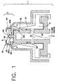
- an aerosol-type dispenser system including a first exemplary embodiment of an aerosol tip or nozzle mechanism 2 according to the present invention is indicated generally at 1.
- the first exemplary embodiment of the aerosol tip mechanism 2 includes a flexible nozzle portion 10 having an outlet portion 108 and a fluid channel or swirling channel 104, a rigid shaft 102 received within the flexible nozzle portion 10, and a rigid external housing 101 surrounding the flexible nozzle portion 10 and exposing the outlet portion 108.
- the rigid shaft 102 interfaces the interior of the outlet portion 108 to form a first normally-closed valve 105, as well as to define a swirling chamber 103 for liquid which has been channeled from a liquid reservoir, prior to being discharged via the outlet portion 108 of the aerosol tip mechanism 2.
- the swirling channel or fluid channel 104 includes gaps between walls 1021a and 1021b circumferentially surrounding the rigid shaft 102.
- the swirling channel 104 which is described in further detail below, channels fluid into the swirling chamber 103.
- a second exemplary embodiment of the aerosol tip or nozzle mechanism 2 according to the present invention is shown in Figs. 6A and 6B.
- the second exemplary embodiment is substantially similar to the first exemplary embodiment, with one exception.
- the second exemplary embodiment of the aerosol tip or nozzle mechanism does not include walls 1021a and 1021b circumferentially surrounding the rigid shaft 102. Accordingly, in the second embodiment shown in Figs. 6A and 6B, the swirling channel 104 is simply an integral part of the swirling chamber 103.
- the first exemplary embodiment of the aerosol tip or nozzle mechanism 2 is coupled to a flexible body portion 107 which has a substantially tubular shape and a wall thickness which decreases from the bottom of the body portion toward the flexible nozzle portion 10, along the elongated axis of symmetry of the body portion.
- the rigid shaft 102 received within the flexible nozzle portion 10 extends down into the flexible body portion 107 go that a second portion 102a of the rigid shaft interfaces the flexible body portion 107 to form a second normally-closed valve 106.
- the fluid communication path 201 of liquid from the liquid reservoir to the outlet portion 108 successively traverses the first and second normally-closed valves 105 and 106, respectively.
- a pump mechanism 110 of the dispenser system acting in concert with a pump-body portion 111 of the dispenser system, channels the liquid from the liquid reservoir along the fluid communication path 201 by application of pressure.
- the nozzle mechanism according to the present invention is intended to be used in conjunction with a wide variety of liquid dispensing systems, one example of which is illustrated in applicant's commonly owned U.S. patent application Serial Number 08/534,609 filed on September 27, 1995, entitled “Fluid Pump Without Dead Volume,” which issued as U.S. Patent No. 5,746,728 on May 5, 1998.
- pump mechanism 110 and the pump-body portion 111 of the dispenser system shown in Figs. 1 and 2 are merely exemplary and generic representation of a wide variety of dispensing systems.
- the liquid from the liquid reservoir is initially channeled through a circumferential channel or groove 109 formed on the exterior of the second portion 102a of the rigid shaft.
- a threshold pressure sufficient to radially deform the flexible body portion 107
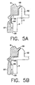
- a portion 501 of the flexible body portion 107 forming a lower segment of the second normally-closed valve 106 is radially deformed by the liquid, thereby opening the second normally-closed valve 106, as shown in Fig. 5A.
- the lower segment 501 of the valve 106 is substantially closed by the time the liquid has reached the upper segment 502. Because the energy required to open the lower segment 501 of the valve 106 is greater than the energy required to open the upper segment 502, the liquid is naturally biased to maintain its forward movement through the second valve 106 in the flexible body portion 107 once the lower segment 501 has been opened. In this manner, the second normally-closed valve 106 ensures liquid movement only in the direction towards the flexible nozzle portion 10.
- the liquid in the fluid communication path 201 has traversed the second normally-closed valve 106, the liquid then enters the fluid channel 104 within the flexible nozzle portion 10 of the first embodiment of the aerosol tip mechanism 2, as shown in Figs. 1, 2 and 3.
- the fluid channel 104 which defines a portion of the fluid communication path 201 between the liquid reservoir and the collecting chamber 103, is circumferentially positioned within the flexible nozzle portion, as shown in Fig. 3.
- the circumferentially positioned fluid channel 104 creates swirling action of the liquid, indicated in Fig. 3 by the directional arrow 301, as it is channeled into the swirling chamber 103.
- the liquid directly enters the swirling chamber 103 via the space 601 once the liquid in the fluid communication path 201 has traversed the second normally-closed valve 106.
- the swirling action of the liquid is maintained in the swirling chamber until the liquid is discharged via the outlet portion 108, the mechanics of which discharging action is described in detail below.
- the liquid in the swirling chamber is discharged via the outlet portion 108 when the liquid pressure reaches a threshold pressure sufficient to radially deform the outlet portion 108 forming the first normally-closed valve 105.
- the liquid movement through the first normally-closed valve 105 involves sequential deformation of segments of the outlet portion 108.
- a portion 401 of the outlet portion 108 forming a lower segment of the first normally-closed valve 105 is radially deformed by the liquid, thereby opening the first normally-closed valve 105.
- the wall thickness of the outlet portion 108 decreases from the lower segment 401 towards the upper segment 402 of the first normally-closed valve 105, i.e., along the elongated axis of symmetry S of the aerosol tip or nozzle mechanism. Due to this steady decrease in wall thickness, the lower segment 401 of the valve 105 is substantially closed by the time the liquid has reached the upper segment 402, as shown in Figs. 4A and 4B. Because the energy required to open the lower segment 401 of the valve 105 is greater than the energy required to open the upper segment 402, the liquid is naturally biased to maintain its forward movement through the first valve 105 in the outlet portion 108 once the lower segment 401 has been opened. Accordingly, the valve 105 ensures liquid movement only in the direction towards the exterior tip of the nozzle portion 10.
- the outlet portion 108 During the discharge of liquid through the outlet portion 108, the only segment of the flexible nozzle portion 10 which experiences deformation along the elongated axis of symmetry S of the aerosol tip or nozzle mechanism is the outlet portion 108.
- the remaining segments of the flexible nozzle portion are prevented by the rigid housing 101 from deformation along the elongated axis of symmetry S.
- the outlet portion 108 does not exert a force along the axis S on the rigid shaft 102, i.e., the outlet portion 108 does not rub the rigid shaft during opening or closing of the first valve 105. Accordingly, because of the absence of any rubbing contact between the outlet portion 108 and the rigid shaft 102, the chances of contaminants entering the swirling chamber 103 are minimized.
- One advantage of the aerosol tip or nozzle mechanism according to the present invention is the above-described prevention of axial deformation of the flexible nozzle portion 10 by the rigid housing 101. Because the flexible nozzle portion 10, with the exception of the outlet portion 108, experiences substantially no deformation along the elongated axis of symmetry S shown in Fig. 4A, the physical profile of the fluid channel 104, which induces swirling action of the liquid channeled into the swirling chamber 103, is maintained during liquid discharge. An axial deformation of the flexible nozzle portion 10 along the direction of liquid discharge would deform the fluid channel 104, which in turn would prevent the swirling action from occurring.
- the flexible nozzle portion 10, the flexible body portion 107 and the pump-body portion 111 may be made of any one of several materials well known in the art, including butadiene polyethylene styrene (KRATONTM), polyethylene, polyurethane or other plastic materials, thermoplastic elastomers or other elastic materials.
- KRATONTM is particularly well suited for this purpose because of its characteristic resistance to permanent deformation, or "creep," which typically occurs with passage of time.
- an aerosol-type dispensing system incorporating the nozzle mechanism according to the present invention can be made using only three discrete parts: the rigid housing 101; an integral, flexible piece encompassing the flexible nozzle portion 10, the flexible body portion 107 and the pump-body portion 111; and the rigid shaft 102 formed integrally with the pump mechanism 110. Because only three discrete parts are required, the cost and complexity of manufacturing an aerosol-type dispensing system is significantly reduced.
- the first normally-closed, one-way valve 105 with its decreasing wall thickness of the outlet portion 108 substantially eliminates the possibility that liquid in the nozzle mechanism will come in contact with ambient air and subsequently return to the interior portion of the nozzle mechanism. Due to the decreasing wall thickness of the outlet portion 108, the liquid is naturally biased to maintain its forward movement through the first valve 105 in the outlet portion 108 once the thicker base portion of the valve has been opened. Accordingly, the outlet portion 108 has a substantially zero "dead volume,” i.e., a space in which liquid that has been previously exposed to ambient air can remain.
- Still another advantage of the aerosol tip or nozzle mechanism according to the present invention is that the outlet portion 108 does not rub the rigid shaft 102 during opening or closing of the first valve 105. Accordingly, because of the absence of any rubbing contact between the outlet portion 108 and the rigid shaft 102, the chances of contaminants entering the swirling chamber 103 are minimized.
- Still another advantage of the aerosol tip or nozzle mechanism according to the present invention is the presence of multiple valves along the fluid communication path leading to the outlet portion 108.
- the second normally-closed valve positioned along the fluid communication path between the liquid reservoir and the outlet adds further assurances that liquid in the liquid reservoir will not be contaminated by liquid that may have been accidentally exposed to ambient air and subsequently reintroduced into the nozzle mechanism. Because the first and second normally-closed valves are positioned along the fluid communication path to open sequentially, and hence asynchronously, during fluid communication leading to discharge through the outlet, failure of either one of the valves will not affect the integrity of the nozzle mechanism to prevent contamination of the liquid in the liquid reservoir.
Landscapes
- Chemical & Material Sciences (AREA)
- Dispersion Chemistry (AREA)
- Engineering & Computer Science (AREA)
- Mechanical Engineering (AREA)
- Containers And Packaging Bodies Having A Special Means To Remove Contents (AREA)
- Nozzles (AREA)
Claims (28)
- Mécanisme de pulvérisation (2) pour distributeur de type aérosol (1) pour délivrer un contenu liquide par application d'une pression, le mécanisme de pulvérisation comportant une partie buse flexible (10) ayant une partie sortie (108) pour délivrer ledit contenu liquide, un axe rigide (102) reçu à l'intérieur de ladite partie buse flexible (10) et servant de jonction pour ladite partie sortie (108) pour former une première vanne normalement fermée (105) et un boítier rigide (101) entourant ladite partie buse flexible (10) et exposant ladite partie sortie (108), dans lequel ledit contenu liquide est expulsé via ladite première vanne normalement fermée (105) lors de l'arrivée à une pression seuil suffisante pour déformer radialement ladite partie sortie (108) afin d'ouvrir ladite première vanne normalement fermée (105), et dans lequel ledit boítier rigide (101) empêche la déformation de la partie buse flexible (10), sauf ladite partie sortie (108), le long de ladite direction axiale pendant l'expulsion dudit contenu liquide par ladite partie sortie (108) ; caractérisé en ce que ladite partie sortie (108) a une forme sensiblement tubulaire et a une épaisseur de paroi qui diminue depuis un premier point le long d'une direction d'axe de symétrie allongé dudit mécanisme de pulvérisation vers un bout de la partie buse flexible, ledit axe rigide (102) et l'intérieur de ladite partie buse flexible (10) définissent une chambre de turbulence (103) pour ledit contenu liquide avant l'expulsion par ladite sortie, et ledit contenu liquide est expulsé de ladite chambre (103) via ladite première vanne normalement fermée (105).
- Mécanisme de pulvérisation selon la revendication 1, dans lequel ledit distributeur (1) est en communication fluide avec un réservoir à liquide, et dans lequel ladite partie buse flexible (10) comprend en outre un canal à fluide (104) définissant une partie d'un chemin de communication fluide (210) entre ledit réservoir à liquide et ladite chambre de turbulence (103), ledit canal (104) produisant une action de turbulence sur le liquide délivré à ladite chambre de turbulence (103).
- Mécanisme de pulvérisation selon la revendication 2, dans lequel ledit canal à fluide (104) est positionné de manière circonférentielle dans ladite partie buse flexible (10).
- Mécanisme de pulvérisation selon la revendication 2, dans lequel ledit boítier rigide (101) empêche en outre la déformation axiale dudit canal à fluide (104).
- Mécanisme de pulvérisation selon la revendication 3, dans lequel ledit boítier rigide (101) empêche en outre la déformation axiale dudit canal à fluide (104).
- Mécanisme de pulvérisation selon la revendication 1, dans lequel ladite déformation radiale de ladite partie sortie (108) pour ouvrir ladite première vanne normalement fermée (105) comprend la déformation séquentielle de parties (401, 402) de ladite partie sortie (108) servant de jonction pour ledit axe rigide (102) le long de la direction axiale, grâce à quoi un point de séparation initial (401) le long de la direction axiale entre ladite partie sortie (108) et ledit axe rigide (102) est substantiellement fermé lorsqu'un point de séparation final (402) le long de la direction axiale entre ladite partie sortie (108) et ledit axe rigide (102) est ouvert.
- Mécanisme de pulvérisation selon la revendication 2, dans lequel ladite déformation radiale de ladite partie sortie (108) pour ouvrir ladite première vanne normalement fermée (105) comprend la déformation séquentielle de parties (401, 402) de ladite partie sortie (108) servant de jonction pour ledit axe rigide (102) le long de la direction axiale, grâce à quoi un point de séparation initial (401) le long de la direction axiale entre ladite partie sortie (108) et ledit axe rigide (102) est substantiellement fermé lorsqu'un point de séparation final (402) le long de la direction axiale entre ladite partie sortie (108) et ledit axe rigide (102) est ouvert.
- Mécanisme de pulvérisation selon la revendication 7, dans lequel ledit canal à fluide (104) est positionné de manière circonférentielle dans ladite partie buse flexible (10).
- Mécanisme de pulvérisation selon la revendication 8, dans lequel ledit boítier rigide (101) empêche en outre la déformation axiale dudit canal à fluide (104).
- Mécanisme de pulvérisation selon la revendication 7, dans lequel ledit boítier rigide (101) empêche en outre la déformation axiale dudit canal à fluide (104).
- Mécanisme de pulvérisation selon la revendication 1, dans lequel ledit distributeur est en communication fluide avec un réservoir à liquide, et dans lequel une partie corps flexible (107) est connectée à ladite partie buse flexible (10), ladite partie corps (107) ayant une forme sensiblement tubulaire et une épaisseur de paroi qui diminue depuis un second point le long de ladite direction axiale vers ledit bout de ladite partie buse flexible (10), ledit axe rigide (102) servant de jonction pour ladite partie corps flexible pour former une seconde vanne normalement fermée (106), dans lequel un contenu dudit réservoir à liquide est conduit dans ladite chambre de turbulence (103) depuis ledit réservoir à liquide via ladite seconde vanne normalement fermée (106) lors de l'application d'une pression suffisante pour ouvrir ladite seconde vanne normalement fermée (106).
- Mécanisme de pulvérisation selon la revendication 11, dans lequel ladite partie buse flexible (10) comprend en outre un canal à fluide (104) définissant une partie d'un chemin de communication fluide (201) entre ledit réservoir à liquide et ladite chambre de turbulence (103), ledit canal à fluide (104) produisant une action de turbulence sur le liquide délivré à ladite chambre de turbulence (103).
- Mécanisme de pulvérisation selon la revendication 12, dans lequel ledit canal à fluide (104) est positionné de manière circonférentielle dans ladite partie buse flexible (10).
- Mécanisme de pulvérisation selon la revendication 12, dans lequel ledit boítier rigide (101) empêche en outre la déformation axiale dudit canal à fluide (104).
- Mécanisme de pulvérisation selon la revendication 13, dans lequel ledit boítier rigide (101) empêche en outre la déformation axiale dudit canal à fluide (104).
- Mécanisme de pulvérisation selon la revendication 11, dans lequel ladite déformation radiale de ladite partie sortie (108) pour ouvrir ladite première vanne normalement fermée (105) comprend la déformation séquentielle de parties (401, 402) de ladite partie sortie (108) servant de jonction pour ledit axe rigide (102) le long de la direction axiale, grâce à quoi un point de séparation initial (401) le long de la direction axiale entre ladite partie sortie (108) et ledit axe rigide (102) est substantiellement fermé lorsqu'un point de séparation final (402) le long de la direction axiale entre ladite partie sortie (108) et ledit axe rigide (102) est ouvert.
- Mécanisme de pulvérisation selon la revendication 16, dans lequel ladite seconde vanne normalement fermée (106) s'ouvre lors de l'application d'une pression suffisante pour déformer radialement ladite partie corps flexible (107) servant de jonction pour ledit axe rigide (102), et dans lequel ladite déformation radiale de ladite partie corps flexible (107) comprend la déformation séquentielle de parties (501, 502) de ladite partie corps flexible (107) servant de jonction pour ledit axe rigide (102), grâce à quoi un point de séparation initial (501) entre ladite partie corps flexible (107) et ledit axe rigide (102) le long de la direction axiale et à l'écart de ladite chambre de turbulence (103) est substantiellement fermé lorsqu'un point de séparation final (502) entre ladite partie corps flexible (107) et ledit axe rigide (102) le long de la direction axiale et près de ladite chambre de turbulence (103) est ouvert.
- Mécanisme de pulvérisation selon la revendication 17, dans lequel on ouvre lesdites première et seconde vannes normalement fermées (105, 106) de manière asynchrone.
- Mécanisme de pulvérisation selon la revendication 12, dans lequel ladite déformation radiale de ladite partie sortie (108) pour ouvrir ladite première vanne normalement fermée (105) comprend la déformation séquentielle de parties (401, 402) de ladite partie sortie (108) servant de jonction pour ledit axe rigide (102) le long de la direction axiale, grâce à quoi un point de séparation initial (401) le long de la direction axiale entre ladite partie sortie (108) et ledit axe rigide (102) est substantiellement fermé lorsqu'un point de séparation final (402) le long de la direction axiale entre ladite partie sortie (108) et ledit axe rigide (102) est ouvert.
- Mécanisme de pulvérisation selon la revendication 19, dans lequel ladite vanne normalement fermée (106) s'ouvre lors de l'application d'une pression suffisante pour déformer radialement ladite partie corps flexible (107) servant de jonction pour ledit axe rigide (102), et dans lequel ladite déformation radiale de ladite partie corps flexible (107) comprend la déformation séquentielle de parties (501, 502) de ladite partie corps flexible (107) servant de jonction pour ledit axe rigide (102), grâce à quoi un point de séparation initial (501) entre ladite partie corps flexible (107) et ledit axe rigide (102) le long de la direction axiale et à l'écart de ladite chambre de turbulence (103) est substantiellement fermé lorsqu'un point de séparation final (502) entre ladite partie corps flexible (107) et ledit axe rigide (102) le long de la direction axiale et près de ladite chambre de turbulence (103) est ouvert.
- Mécanisme de pulvérisation selon la revendication 20, dans lequel on ouvre lesdites première et seconde vannes normalement fermées (105, 106) de manière asynchrone.
- Mécanisme de pulvérisation selon la revendication 21, dans lequel ledit canal à fluide (104) est positionné de manière circonférentielle dans ladite partie buse flexible (10).
- Mécanisme de pulvérisation selon la revendication 22, dans lequel ledit boítier rigide (101) empêche en outre la déformation axiale du canal à fluide (104).
- Mécanisme de pulvérisation selon la revendication 19, dans lequel ledit canal à fluide (104) est positionné de manière circonférentielle dans ladite partie buse flexible (10).
- Mécanisme de pulvérisation selon la revendication 24, dans lequel ledit boítier rigide (101) empêche en outre la déformation axiale du canal à fluide (104).
- Procédé de production d'une décharge de fluide de type aérosol depuis un distributeur (1) en communication fluide avec un réservoir à liquide, ledit distributeur (1) comprenant une partie buse flexible (10) ayant une partie sortie (108) pour délivrer ledit contenu liquide, ladite partie sortie (108) ayant une épaisseur de paroi qui diminue depuis un premier point le long d'une direction d'axe de symétrie allongé de ladite partie buse (10) vers un bout de la partie buse flexible (10), une première partie d'un axe rigide (102) reçue dans la partie buse flexible (10 ) et servant de jonction pour ladite partie sortie (108) pour former une première vanne normalement fermée (105), ladite première partie dudit axe rigide (102) et l'intérieur de ladite partie buse flexible (10) définissant une chambre de turbulence (103) pour ledit contenu liquide avant l'expulsion par ladite sortie, ladite partie buse flexible (10) comprenant en outre un canal à fluide positionné de manière circonférentielle (104) définissant une partie d'un chemin de communication fluide (201) entre ledit réservoir à liquide et ladite chambre de turbulence (103), et un boítier rigide (101) entourant ladite partie buse flexible (10) et exposant ladite partie sortie (108), lequel procédé comprend les opérations consistant à :dans lequel ladite déformation radiale de ladite partie sortie (108) pour ouvrir ladite première vanne normalement fermée (105) comprend la déformation séquentielle de parties (401, 402) de ladite partie sortie (108) servant de jonction pour ladite première partie dudit axe rigide (102) le long de la direction axiale, grâce à quoi un point de séparation initial (401) le long de la direction axiale entre ladite partie sortie (108) et ladite première partie dudit axe rigide (102) est substantiellement fermé lorsqu'un point de séparation final (402) le long de la direction axiale entre ladite partie sortie (108) et ladite première partie dudit axe rigide (102) est ouvert.conduire le contenu liquide dudit réservoir à liquide dans ledit chemin de communication fluide (201) par application d'une pression ;conduire ledit contenu liquide dans ladite chambre de turbulence (103) via ledit canal à fluide positionné de manière circonférentielle (104) par application d'une pression, en créant de ce fait un mouvement turbulent dudit contenu liquide dans ladite chambre de turbulence (103) ; etexpulser ledit contenu liquide de ladite chambre de turbulence (103) par ladite sortie via ladite première vanne normalement fermée (105) par application d'une pression suffisante pour déformer radialement ladite partie sortie (108) afin d'ouvrir ladite première vanne normalement fermée (105) tout en empêchant substantiellement la déformation de ladite partie sortie (108) le long de la direction axiale par une poussée relative dudit boítier rigide (101) ;
- Procédé selon la revendication 26, dans lequel ledit distributeur (1) comprend en outre une partie corps flexible (107) connectée à ladite partie buse flexible (10), ladite partie corps (107) ayant une épaisseur de paroi qui diminue depuis un second point le long de ladite direction axiale vers ledit bout de ladite partie buse flexible (10), et dans lequel ledit axe rigide (102) comprend en outre une seconde partie servant de jonction pour ladite partie corps flexible (107) pour former une seconde vanne normalement fermée (106) dans ledit chemin de communication fluide (201), lequel procédé comprend en outre, avant l'étape de conduite dudit contenu liquide dans ladite chambre de turbulence (103) via ledit canal à fluide positionné de manière circonférentielle (104), les étapes consistant à :conduire ledit contenu liquide via ladite seconde vanne normalement fermée (106) dans ledit canal à fluide positionné de manière circonférentielle (104) par application d'une pression pour déformer radialement ladite partie corps flexible (107) servant de jonction pour ladite seconde partie dudit axe rigide (102) pour ouvrir ladite seconde vanne normalement fermée (106), ladite déformation radiale de ladite partie corps flexible (107) comprenant la déformation séquentielle de parties (501, 502) de ladite partie corps flexible (107) servant de jonction pour ladite seconde partie dudit axe rigide (102), grâce à quoi un point de séparation initial (501) entre ladite partie corps flexible (107) et ladite seconde partie dudit axe rigide (102) le long de la direction axiale et à l'écart dudit canal à fluide positionné de manière circonférentielle (104) est substantiellement fermé lorsqu'un point de séparation final (502) entre ladite partie corps flexible (107) et ladite seconde partie dudit axe rigide (102) le long de la direction axiale et près dudit canal à fluide positionné de manière circonférentielle (104) est ouvert.
- Procédé selon la revendication 27, dans lequel on ouvre lesdites première et seconde vannes normalement fermées (105, 106) de manière asynchrone.
Applications Claiming Priority (2)
| Application Number | Priority Date | Filing Date | Title |
|---|---|---|---|
| US927221 | 1997-09-10 | ||
| US08/927,221 US5855322A (en) | 1997-09-10 | 1997-09-10 | System and method for one-way spray aerosol tip |
Publications (3)
| Publication Number | Publication Date |
|---|---|
| EP0906786A2 EP0906786A2 (fr) | 1999-04-07 |
| EP0906786A3 EP0906786A3 (fr) | 2000-11-08 |
| EP0906786B1 true EP0906786B1 (fr) | 2003-12-03 |
Family
ID=25454418
Family Applications (1)
| Application Number | Title | Priority Date | Filing Date |
|---|---|---|---|
| EP98307246A Expired - Lifetime EP0906786B1 (fr) | 1997-09-10 | 1998-09-08 | Système et procédé pour embout de pulvérisation ou de production d'aérosols à écoulement unidirectionel |
Country Status (11)
| Country | Link |
|---|---|
| US (2) | US5855322A (fr) |
| EP (1) | EP0906786B1 (fr) |
| JP (1) | JP4074949B2 (fr) |
| KR (1) | KR100578444B1 (fr) |
| AR (1) | AR015436A1 (fr) |
| AT (1) | ATE255469T1 (fr) |
| AU (1) | AU732591B2 (fr) |
| BR (1) | BR9803401A (fr) |
| CA (1) | CA2246294C (fr) |
| DE (1) | DE69820189T2 (fr) |
| ES (1) | ES2212228T3 (fr) |
Families Citing this family (44)
| Publication number | Priority date | Publication date | Assignee | Title |
|---|---|---|---|---|
| FR2773784B1 (fr) * | 1998-01-16 | 2000-03-24 | Valois Sa | Tete de pulverisation pour un distributeur de produit fluide |
| DE19849687A1 (de) * | 1998-10-28 | 2000-05-04 | Valeo Auto Electric Gmbh | Düsenelement für eine Scheibenwaschanlage eines Kraffahrzeuges |
| FR2792552B1 (fr) * | 1999-04-20 | 2002-04-19 | Valois Sa | Tete de pulverisation de produit fluide comportant un obturateur ameliore |
| US6254579B1 (en) | 1999-11-08 | 2001-07-03 | Allergan Sales, Inc. | Multiple precision dose, preservative-free medication delivery system |
| US6302101B1 (en) | 1999-12-14 | 2001-10-16 | Daniel Py | System and method for application of medicament into the nasal passage |
| US6398766B1 (en) * | 1999-12-27 | 2002-06-04 | Vista Innovations, Inc. | Eye wash system |
| US6524287B1 (en) | 2000-10-10 | 2003-02-25 | Advanced Medical Optics | Housing apparatus with rear activated return button for instilling a medication into an eye |
| US6533764B1 (en) | 2000-11-06 | 2003-03-18 | Allergan, Inc. | Twist housing apparatus for instilling a medication into an eye |
| US6415957B1 (en) * | 2000-11-27 | 2002-07-09 | S. C. Johnson & Son, Inc. | Apparatus for dispensing a heated post-foaming gel |
| US6543703B2 (en) * | 2000-12-26 | 2003-04-08 | William S. Blake | Flexible face non-clogging actuator assembly |
| US6506183B2 (en) | 2001-02-02 | 2003-01-14 | Advanced Medical Optics | One shot actuation housing apparatus for instilling a medication into an eye |
| US6685109B2 (en) * | 2001-09-24 | 2004-02-03 | Daniel Py | System and method for a two piece spray nozzle |
| GB2411609B (en) * | 2001-09-24 | 2006-02-22 | Py Daniel C | Method of controlling the particle size of aerosol discharged fluid |
| AU2003226934A1 (en) * | 2002-04-10 | 2003-10-27 | Disop-Nordic Holding Aps | Tube with self-closing mechanism for liquid container |
| US6609666B1 (en) * | 2002-07-24 | 2003-08-26 | William Sydney Blake | Unitary over-mold non-clog system with positive shutoff |
| DE10315934B4 (de) * | 2003-04-02 | 2005-08-04 | Ing. Erich Pfeiffer Gmbh | Austragkopf für eine Dosiervorrichtung |
| US8012136B2 (en) * | 2003-05-20 | 2011-09-06 | Optimyst Systems, Inc. | Ophthalmic fluid delivery device and method of operation |
| ATE501766T1 (de) * | 2003-05-20 | 2011-04-15 | James F Collins | Ophthalmisches arzneimittelabgabesystem |
| US20050056708A1 (en) * | 2003-09-12 | 2005-03-17 | Castillo Higareda Jose De Jesus | Apparatus for inducing turbulence in a fluid and method of manufacturing same |
| CN1901966A (zh) * | 2003-11-14 | 2007-01-24 | 因斯蒂尔医学技术有限公司 | 输送装置及输送方法 |
| US7264142B2 (en) | 2004-01-27 | 2007-09-04 | Medical Instill Technologies, Inc. | Dispenser having variable-volume storage chamber and depressible one-way valve assembly for dispensing creams and other substances |
| WO2006037112A2 (fr) | 2004-09-27 | 2006-04-06 | Medical Instill Technologies, Inc. | Distributeur a actionnement lateral pourvu d'une valve de non-retour pour stocker et distribuer des quantites de substances |
| GB0515592D0 (en) | 2005-07-28 | 2005-09-07 | Glaxo Group Ltd | Nozzle for a nasal inhaler |
| FR2902675B1 (fr) * | 2006-06-21 | 2008-09-12 | Lvmh Rech | Buse de distribution de produit de fluide et dispositif de distribution de produit de fluide comprenant une telle buse |
| WO2008061041A2 (fr) * | 2006-11-11 | 2008-05-22 | Medical Instill Technologies, Inc. | Dispositif d'administration de doses multiples avec actionneur enfoncable manuellement et valve a sens unique pour stocker et distribuer des substances, et procédé apparente |
| FR2912071B1 (fr) | 2007-02-05 | 2011-03-18 | De La Mer Laboratoire | Embout de pulverisation,container unidose pulverisateur et kit de pulverisation unidose. |
| CA2688689C (fr) * | 2007-05-16 | 2015-06-30 | Mystic Pharmaceuticals, Inc. | Contenants combines de distribution-dose unitaire |
| US20090212133A1 (en) * | 2008-01-25 | 2009-08-27 | Collins Jr James F | Ophthalmic fluid delivery device and method of operation |
| FR2933680B1 (fr) * | 2008-07-11 | 2013-01-18 | Valois Sa | Pompe de distribution de produit fluide |
| KR101029747B1 (ko) | 2008-09-30 | 2011-04-19 | (주)프로템 | 건조기의 플로팅 노즐 |
| US10154923B2 (en) | 2010-07-15 | 2018-12-18 | Eyenovia, Inc. | Drop generating device |
| JP2013531044A (ja) | 2010-07-15 | 2013-08-01 | コリンシアン オフサルミック,インコーポレイティド | 点眼薬送達 |
| EA201390121A8 (ru) | 2010-07-15 | 2014-02-28 | Коринтиан Офтэлмик, Инк. | Способ и система для выполнения дистанционного лечения и контроля |
| EP2593056B1 (fr) | 2010-07-15 | 2020-10-21 | Eyenovia, Inc. | Dispositif de génération de gouttelettes |
| EP2790619A1 (fr) | 2011-12-12 | 2014-10-22 | Corinthian Ophthalmic, Inc. | Mécanisme éjecteur, dispositif éjecteur et procédés d'utilisation |
| US9415401B2 (en) | 2012-04-04 | 2016-08-16 | Alternative Packaging Solutions Llc | One turn actuated duration spray pump mechanism |
| DE102013215599B4 (de) * | 2013-08-07 | 2017-12-07 | Aptar Radolfzell Gmbh | Pumpeinrichtung und Spender für flüssige oder pastöse Medien |
| US11045819B2 (en) * | 2015-12-04 | 2021-06-29 | Medspray B.V. | Fluidic sprayer |
| DE102017104739A1 (de) | 2017-03-07 | 2018-09-13 | Ursatec Verpackung Gmbh | Fluidspender |
| DE102017104740A1 (de) | 2017-03-07 | 2018-09-13 | Ursatec Verpackung Gmbh | Fluidspender |
| EP3634550A4 (fr) | 2017-06-10 | 2021-03-03 | Eyenovia, Inc. | Procédés et dispositifs pour manipuler un fluide et administrer le fluide à l'oeil |
| US11123220B1 (en) | 2017-11-21 | 2021-09-21 | CryoXcel, LLC | Gas delivery system for cryochamber |
| FR3078271B1 (fr) * | 2018-02-27 | 2022-08-05 | Albea Services | Tete de distribution a chambre tourbillonnaire etagee pour un systeme de distribution |
| CN115038414A (zh) | 2019-12-11 | 2022-09-09 | 艾诺维亚股份有限公司 | 用于向眼睛输送流体的系统和装置及使用方法 |
Family Cites Families (17)
| Publication number | Priority date | Publication date | Assignee | Title |
|---|---|---|---|---|
| US3739952A (en) * | 1971-07-09 | 1973-06-19 | Gillette Co | Intermittent dispensing device |
| US4313569A (en) * | 1980-05-27 | 1982-02-02 | Ethyl Products Company | Fluid dispenser method and apparatus |
| DE3339180C2 (de) * | 1983-10-28 | 1993-10-14 | Pfeiffer Erich Gmbh & Co Kg | Austragvorrichtung für Medien |
| US4623337A (en) * | 1984-03-08 | 1986-11-18 | Alpha Group, Inc. | Liquid dispensing apparatus |
| US4946452A (en) * | 1987-11-06 | 1990-08-07 | Py Daniel C | Ocular treatment apparatus |
| US4981479A (en) * | 1987-11-06 | 1991-01-01 | Py Daniel C | Ocular treatment apparatus |
| US5133702A (en) * | 1987-11-06 | 1992-07-28 | O.P.T.I.C. | Ocular treatment apparatus |
| EP0378935B1 (fr) * | 1988-12-20 | 1992-09-23 | Societe Technique De Pulverisation (S.T.E.P.) | Dispositif pour distribuer un liquide ou un lait par goutte de petit volume et ensemble de distribution associée |
| WO1993002729A1 (fr) * | 1990-07-12 | 1993-02-18 | Habley Medical Technology Corporation | Inhalateur de medicaments a atomisation tres fine, contenant du fluorocarbone non chlore |
| DE4041136C2 (de) * | 1990-12-21 | 1994-06-30 | Andris Raimund Gmbh & Co Kg | Dosier- und Spraypumpe zur Abgabe flüssiger, niederviskoser und pastöser Stoffe |
| GB9114080D0 (en) * | 1991-06-28 | 1991-08-14 | Weston Terence E | Atomising valve |
| EP0615460B1 (fr) * | 1991-12-02 | 1999-06-02 | PY, Daniel | Dispositif d'application d'un medicament sur l'oeil |
| AU656386B2 (en) * | 1992-01-21 | 1995-02-02 | Central Valley Manufacturing, Inc. | Pulsator for irrigation systems and the like |
| US5401259A (en) * | 1992-04-06 | 1995-03-28 | Py Daniel C | Cartridge for applying medicament to an eye |
| US5320845A (en) * | 1993-01-06 | 1994-06-14 | Py Daniel C | Apparatus for delivering multiple medicaments to an eye without premixing in the apparatus |
| US5358179A (en) * | 1993-08-18 | 1994-10-25 | The Procter & Gamble Company | Atomization systems for high viscosity products |
| FR2723618B1 (fr) * | 1994-08-11 | 1996-10-31 | Sofab | Pompe a membrane |
-
1997
- 1997-09-10 US US08/927,221 patent/US5855322A/en not_active Expired - Lifetime
-
1998
- 1998-09-01 CA CA002246294A patent/CA2246294C/fr not_active Expired - Fee Related
- 1998-09-08 AT AT98307246T patent/ATE255469T1/de not_active IP Right Cessation
- 1998-09-08 AR ARP980104470A patent/AR015436A1/es unknown
- 1998-09-08 ES ES98307246T patent/ES2212228T3/es not_active Expired - Lifetime
- 1998-09-08 DE DE69820189T patent/DE69820189T2/de not_active Expired - Lifetime
- 1998-09-08 EP EP98307246A patent/EP0906786B1/fr not_active Expired - Lifetime
- 1998-09-09 AU AU83216/98A patent/AU732591B2/en not_active Ceased
- 1998-09-09 JP JP25572098A patent/JP4074949B2/ja not_active Expired - Fee Related
- 1998-09-09 BR BR9803401-4A patent/BR9803401A/pt not_active Application Discontinuation
- 1998-09-09 KR KR1019980037118A patent/KR100578444B1/ko not_active Expired - Fee Related
- 1998-11-16 US US09/192,843 patent/US6053433A/en not_active Expired - Lifetime
Also Published As
| Publication number | Publication date |
|---|---|
| CA2246294A1 (fr) | 1999-03-10 |
| EP0906786A2 (fr) | 1999-04-07 |
| DE69820189D1 (de) | 2004-01-15 |
| AR015436A1 (es) | 2001-05-02 |
| JPH11189282A (ja) | 1999-07-13 |
| EP0906786A3 (fr) | 2000-11-08 |
| KR19990029656A (ko) | 1999-04-26 |
| HK1019315A1 (en) | 2000-02-03 |
| BR9803401A (pt) | 2001-03-20 |
| JP4074949B2 (ja) | 2008-04-16 |
| ATE255469T1 (de) | 2003-12-15 |
| KR100578444B1 (ko) | 2006-07-25 |
| ES2212228T3 (es) | 2004-07-16 |
| DE69820189T2 (de) | 2004-09-16 |
| US5855322A (en) | 1999-01-05 |
| US6053433A (en) | 2000-04-25 |
| AU8321698A (en) | 1999-03-25 |
| CA2246294C (fr) | 2009-01-20 |
| AU732591B2 (en) | 2001-04-26 |
Similar Documents
| Publication | Publication Date | Title |
|---|---|---|
| EP0906786B1 (fr) | Système et procédé pour embout de pulvérisation ou de production d'aérosols à écoulement unidirectionel | |
| US6505622B2 (en) | System and method for application of medicament into the nasal passage | |
| AU730007B2 (en) | Dispenser for media | |
| JP3355459B2 (ja) | 流体を噴霧または分与する装置 | |
| EP0352532A2 (fr) | Valve à sommet plat pour atomiseur à pompe | |
| EP1343403A1 (fr) | Pompe de dosage destinee a des distributeurs de liquide | |
| CZ295103B6 (cs) | Zařízení miniaturní konstrukce pro tlakování tekutiny, rozprašovač pro rozprašování tekutiny a čerpací zařízení s vratným pohybem pro vytváření vysokého tlaku v tekutině | |
| JPH03210075A (ja) | 半流動性物質用分与ヘッドの出口通路用シャッタ及びこのシャッタに好適に関連する分与ヘッド | |
| EP1597173B1 (fr) | Valves de dosage pour distributeurs | |
| WO2006126014A2 (fr) | Clapet de non-retour et dispositif fluidique a corps fendu comportant ce clapet de non-retour | |
| KR19990072902A (ko) | 매질배출용디스펜서 | |
| EP0998355B1 (fr) | Bouton-poussoir comportant une buse mobile destinee a liberer des fluides mis sous pression | |
| HK1019315B (en) | System and method for one-way spray/aerosol tip | |
| GB2340477A (en) | Metering valve | |
| MXPA98007337A (en) | System and method for spray tip / spray of a p | |
| WO2004009471A2 (fr) | Mecanisme de soupape pour inhalateur | |
| CA2592954C (fr) | Nouvelles methodes de synthese d'alfentanil, de sufentanil et de remifentanil | |
| EP4703045A1 (fr) | Tête de distribution et distributeur de fluide doté d'une telle tête de distribution | |
| NZ245498A (en) | Trigger-operated hand pump; pump chamber comprises a resilient flexible tube with a corrugated bellows section |
Legal Events
| Date | Code | Title | Description |
|---|---|---|---|
| PUAI | Public reference made under article 153(3) epc to a published international application that has entered the european phase |
Free format text: ORIGINAL CODE: 0009012 |
|
| AK | Designated contracting states |
Kind code of ref document: A2 Designated state(s): AT BE CH DE DK ES FR GB IE IT LI NL PT SE |
|
| AX | Request for extension of the european patent |
Free format text: AL;LT;LV;MK;RO;SI |
|
| PUAL | Search report despatched |
Free format text: ORIGINAL CODE: 0009013 |
|
| AK | Designated contracting states |
Kind code of ref document: A3 Designated state(s): AT BE CH CY DE DK ES FI FR GB GR IE IT LI LU MC NL PT SE |
|
| AX | Request for extension of the european patent |
Free format text: AL;LT;LV;MK;RO;SI |
|
| RIC1 | Information provided on ipc code assigned before grant |
Free format text: 7B 05B 11/00 A, 7B 05B 1/32 B, 7B 05B 1/34 B, 7B 65D 47/20 B |
|
| 17P | Request for examination filed |
Effective date: 20010411 |
|
| AKX | Designation fees paid |
Free format text: AT BE CH DE DK ES FR GB IE IT LI NL PT SE |
|
| 17Q | First examination report despatched |
Effective date: 20020508 |
|
| GRAH | Despatch of communication of intention to grant a patent |
Free format text: ORIGINAL CODE: EPIDOS IGRA |
|
| GRAS | Grant fee paid |
Free format text: ORIGINAL CODE: EPIDOSNIGR3 |
|
| GRAA | (expected) grant |
Free format text: ORIGINAL CODE: 0009210 |
|
| AK | Designated contracting states |
Kind code of ref document: B1 Designated state(s): AT BE CH DE DK ES FR GB IE IT LI NL PT SE |
|
| PG25 | Lapsed in a contracting state [announced via postgrant information from national office to epo] |
Ref country code: NL Free format text: LAPSE BECAUSE OF FAILURE TO SUBMIT A TRANSLATION OF THE DESCRIPTION OR TO PAY THE FEE WITHIN THE PRESCRIBED TIME-LIMIT Effective date: 20031203 Ref country code: LI Free format text: LAPSE BECAUSE OF FAILURE TO SUBMIT A TRANSLATION OF THE DESCRIPTION OR TO PAY THE FEE WITHIN THE PRESCRIBED TIME-LIMIT Effective date: 20031203 Ref country code: CH Free format text: LAPSE BECAUSE OF FAILURE TO SUBMIT A TRANSLATION OF THE DESCRIPTION OR TO PAY THE FEE WITHIN THE PRESCRIBED TIME-LIMIT Effective date: 20031203 Ref country code: AT Free format text: LAPSE BECAUSE OF FAILURE TO SUBMIT A TRANSLATION OF THE DESCRIPTION OR TO PAY THE FEE WITHIN THE PRESCRIBED TIME-LIMIT Effective date: 20031203 |
|
| REG | Reference to a national code |
Ref country code: GB Ref legal event code: FG4D |
|
| REG | Reference to a national code |
Ref country code: CH Ref legal event code: EP |
|
| REG | Reference to a national code |
Ref country code: IE Ref legal event code: FG4D |
|
| REF | Corresponds to: |
Ref document number: 69820189 Country of ref document: DE Date of ref document: 20040115 Kind code of ref document: P |
|
| PG25 | Lapsed in a contracting state [announced via postgrant information from national office to epo] |
Ref country code: DK Free format text: LAPSE BECAUSE OF FAILURE TO SUBMIT A TRANSLATION OF THE DESCRIPTION OR TO PAY THE FEE WITHIN THE PRESCRIBED TIME-LIMIT Effective date: 20040303 |
|
| REG | Reference to a national code |
Ref country code: SE Ref legal event code: TRGR |
|
| NLV1 | Nl: lapsed or annulled due to failure to fulfill the requirements of art. 29p and 29m of the patents act | ||
| REG | Reference to a national code |
Ref country code: CH Ref legal event code: PL |
|
| REG | Reference to a national code |
Ref country code: ES Ref legal event code: FG2A Ref document number: 2212228 Country of ref document: ES Kind code of ref document: T3 |
|
| PGFP | Annual fee paid to national office [announced via postgrant information from national office to epo] |
Ref country code: IE Payment date: 20040928 Year of fee payment: 7 |
|
| ET | Fr: translation filed | ||
| PLBE | No opposition filed within time limit |
Free format text: ORIGINAL CODE: 0009261 |
|
| STAA | Information on the status of an ep patent application or granted ep patent |
Free format text: STATUS: NO OPPOSITION FILED WITHIN TIME LIMIT |
|
| 26N | No opposition filed |
Effective date: 20040906 |
|
| PG25 | Lapsed in a contracting state [announced via postgrant information from national office to epo] |
Ref country code: IE Free format text: LAPSE BECAUSE OF NON-PAYMENT OF DUE FEES Effective date: 20050908 |
|
| REG | Reference to a national code |
Ref country code: IE Ref legal event code: MM4A |
|
| PG25 | Lapsed in a contracting state [announced via postgrant information from national office to epo] |
Ref country code: PT Free format text: LAPSE BECAUSE OF NON-PAYMENT OF DUE FEES Effective date: 20040503 |
|
| BERE | Be: lapsed |
Owner name: *PY DANIEL Effective date: 20100930 |
|
| PGFP | Annual fee paid to national office [announced via postgrant information from national office to epo] |
Ref country code: IT Payment date: 20110219 Year of fee payment: 13 |
|
| PG25 | Lapsed in a contracting state [announced via postgrant information from national office to epo] |
Ref country code: BE Free format text: LAPSE BECAUSE OF NON-PAYMENT OF DUE FEES Effective date: 20100930 |
|
| PGFP | Annual fee paid to national office [announced via postgrant information from national office to epo] |
Ref country code: ES Payment date: 20110128 Year of fee payment: 13 |
|
| PGFP | Annual fee paid to national office [announced via postgrant information from national office to epo] |
Ref country code: BE Payment date: 20110722 Year of fee payment: 13 |
|
| BERE | Be: lapsed |
Owner name: *PY DANIEL Effective date: 20110930 |
|
| PG25 | Lapsed in a contracting state [announced via postgrant information from national office to epo] |
Ref country code: IT Free format text: LAPSE BECAUSE OF NON-PAYMENT OF DUE FEES Effective date: 20110908 |
|
| PG25 | Lapsed in a contracting state [announced via postgrant information from national office to epo] |
Ref country code: BE Free format text: LAPSE BECAUSE OF NON-PAYMENT OF DUE FEES Effective date: 20110930 |
|
| REG | Reference to a national code |
Ref country code: ES Ref legal event code: FD2A Effective date: 20130530 |
|
| PG25 | Lapsed in a contracting state [announced via postgrant information from national office to epo] |
Ref country code: ES Free format text: LAPSE BECAUSE OF NON-PAYMENT OF DUE FEES Effective date: 20110909 |
|
| REG | Reference to a national code |
Ref country code: FR Ref legal event code: PLFP Year of fee payment: 19 |
|
| REG | Reference to a national code |
Ref country code: FR Ref legal event code: PLFP Year of fee payment: 20 |
|
| PGFP | Annual fee paid to national office [announced via postgrant information from national office to epo] |
Ref country code: DE Payment date: 20170905 Year of fee payment: 20 Ref country code: GB Payment date: 20170906 Year of fee payment: 20 Ref country code: FR Payment date: 20170810 Year of fee payment: 20 |
|
| PGFP | Annual fee paid to national office [announced via postgrant information from national office to epo] |
Ref country code: SE Payment date: 20170912 Year of fee payment: 20 |
|
| REG | Reference to a national code |
Ref country code: DE Ref legal event code: R071 Ref document number: 69820189 Country of ref document: DE |
|
| REG | Reference to a national code |
Ref country code: GB Ref legal event code: PE20 Expiry date: 20180907 |
|
| PG25 | Lapsed in a contracting state [announced via postgrant information from national office to epo] |
Ref country code: GB Free format text: LAPSE BECAUSE OF EXPIRATION OF PROTECTION Effective date: 20180907 |