EP0906583B1 - Magnetische lesevorrichtungen - Google Patents
Magnetische lesevorrichtungen Download PDFInfo
- Publication number
- EP0906583B1 EP0906583B1 EP97927276A EP97927276A EP0906583B1 EP 0906583 B1 EP0906583 B1 EP 0906583B1 EP 97927276 A EP97927276 A EP 97927276A EP 97927276 A EP97927276 A EP 97927276A EP 0906583 B1 EP0906583 B1 EP 0906583B1
- Authority
- EP
- European Patent Office
- Prior art keywords
- magnetic
- magnet
- tag
- detector
- magnets
- Prior art date
- Legal status (The legal status is an assumption and is not a legal conclusion. Google has not performed a legal analysis and makes no representation as to the accuracy of the status listed.)
- Expired - Lifetime
Links
- 238000004804 winding Methods 0.000 claims abstract description 8
- 230000008859 change Effects 0.000 claims abstract description 7
- 230000005855 radiation Effects 0.000 claims abstract description 7
- 238000012545 processing Methods 0.000 claims description 4
- 230000005415 magnetization Effects 0.000 abstract 3
- 238000000034 method Methods 0.000 description 11
- 239000000463 material Substances 0.000 description 8
- 239000000696 magnetic material Substances 0.000 description 6
- 230000035945 sensitivity Effects 0.000 description 6
- 230000004907 flux Effects 0.000 description 5
- 229910052751 metal Inorganic materials 0.000 description 5
- 239000002184 metal Substances 0.000 description 5
- 238000013461 design Methods 0.000 description 4
- 238000001514 detection method Methods 0.000 description 4
- 238000004519 manufacturing process Methods 0.000 description 4
- 238000010276 construction Methods 0.000 description 3
- 230000003068 static effect Effects 0.000 description 3
- XEEYBQQBJWHFJM-UHFFFAOYSA-N Iron Chemical compound [Fe] XEEYBQQBJWHFJM-UHFFFAOYSA-N 0.000 description 2
- 238000013459 approach Methods 0.000 description 2
- 230000015572 biosynthetic process Effects 0.000 description 2
- 230000000694 effects Effects 0.000 description 2
- 239000004459 forage Substances 0.000 description 2
- 230000035699 permeability Effects 0.000 description 2
- RYGMFSIKBFXOCR-UHFFFAOYSA-N Copper Chemical compound [Cu] RYGMFSIKBFXOCR-UHFFFAOYSA-N 0.000 description 1
- CWYNVVGOOAEACU-UHFFFAOYSA-N Fe2+ Chemical compound [Fe+2] CWYNVVGOOAEACU-UHFFFAOYSA-N 0.000 description 1
- 229910052772 Samarium Inorganic materials 0.000 description 1
- 229910045601 alloy Inorganic materials 0.000 description 1
- 239000000956 alloy Substances 0.000 description 1
- 230000009286 beneficial effect Effects 0.000 description 1
- 239000000969 carrier Substances 0.000 description 1
- 229910017052 cobalt Inorganic materials 0.000 description 1
- 239000010941 cobalt Substances 0.000 description 1
- GUTLYIVDDKVIGB-UHFFFAOYSA-N cobalt atom Chemical compound [Co] GUTLYIVDDKVIGB-UHFFFAOYSA-N 0.000 description 1
- 230000008878 coupling Effects 0.000 description 1
- 238000010168 coupling process Methods 0.000 description 1
- 238000005859 coupling reaction Methods 0.000 description 1
- 230000007423 decrease Effects 0.000 description 1
- 230000000593 degrading effect Effects 0.000 description 1
- 230000001419 dependent effect Effects 0.000 description 1
- 238000003306 harvesting Methods 0.000 description 1
- 238000003384 imaging method Methods 0.000 description 1
- 230000006872 improvement Effects 0.000 description 1
- 229910052742 iron Inorganic materials 0.000 description 1
- 238000002955 isolation Methods 0.000 description 1
- 238000005259 measurement Methods 0.000 description 1
- 230000008569 process Effects 0.000 description 1
- 229910052761 rare earth metal Inorganic materials 0.000 description 1
- 230000004044 response Effects 0.000 description 1
- KZUNJOHGWZRPMI-UHFFFAOYSA-N samarium atom Chemical compound [Sm] KZUNJOHGWZRPMI-UHFFFAOYSA-N 0.000 description 1
- 229920006395 saturated elastomer Polymers 0.000 description 1
- 239000007787 solid Substances 0.000 description 1
Images


Classifications
-
- G—PHYSICS
- G01—MEASURING; TESTING
- G01V—GEOPHYSICS; GRAVITATIONAL MEASUREMENTS; DETECTING MASSES OR OBJECTS; TAGS
- G01V3/00—Electric or magnetic prospecting or detecting; Measuring magnetic field characteristics of the earth, e.g. declination, deviation
- G01V3/08—Electric or magnetic prospecting or detecting; Measuring magnetic field characteristics of the earth, e.g. declination, deviation operating with magnetic or electric fields produced or modified by objects or geological structures or by detecting devices
Definitions
- This invention relates to magnetic sensing and reading devices and, more particularly, is concerned with detectors (or readers) for reading information stored in magnetic tags or elements.
- WO96/31790 (published 10 October, 1996) defines a magnetic null as: "a point, line, plane or volume in space at or within which the component of the magnetic field in a given linear direction is zero" - see page 3 line 34 to page 4 line 2 of that document.
- the basic technique described is not restricted to low coercivity material, and the present application is concerned with a detector which is capable of interrogating tags containing elements made from magnetic material with coercivity ranging from very low (1 A/m or less) up to high (30,000 A/m or more).
- This type of embodiment is particularly efficient for high coercivity material because it avoids the need for the high amplitude a.c. interrogation field which would otherwise be required for such material.
- Other advantages include a high data rate, and simplicity.
- the invention is particularly suitable for extracting information from items such as security documents and banknotes which already contain magnetic elements made from material having a wide range of coercivities. It will thus be appreciated that the term "tag" as used herein encompasses within its scope items such as security documents and banknotes incorporating one or more magnetic elements.
- US-A-3 964 042 (D1 - Garrott) describes a metal detector for detecting ferrous objects such as nuts and bolts, particularly in the context of forage harvesting machines, where it is apparently common for machine parts made of iron or other magnetic materials to break away and cause damage to the forage processing parts of the machine.
- the metal detector utilises permanent magnets to generate a static magnetic field, the magnets being arranged so that the lines of magnetic force extend between poles of opposite polarity in a first plane which will be intersected by the passage of extraneous metal objects into the machine.
- a detecting coil is arranged around the permanent magnets in a second plane which is perpendicular to said first plane. As illustrated, the coil is positioned in a horizontal plane.
- the coil is therefore sensitive to flux changes occurring within a vertical plane (i.e. perpendicular to that of the coil).
- four magnetic poles are arranged in the configuration: ----N 1 -----S 2 ---- ----S 1 -----N 2 ---- This is achieved by using two magnets of generally horseshoe cross section placed in contact side by side. There are thus two magnetic discontinuities, both occurring in the vertical plane which passes through the contact plane between the two magnets. Such an arrangement cannot detect the passage of a magnetic element having an axis of easy magnetisation through the magnetic null (which lies in a vertical plane with the geometry of Figs. 2 and 3 of D1).
- EP-A-0 295 085 (D2 - Scientific Generics Ltd) describes a method of detecting the presence of articles by applying to them preselected magnetic tags, these being arranged in a coded formation so that magnetic interrogation can be used to determine the presence of the article. There is no disclosure of the use of an interrogating field such as is used in the present application.
- US-A-5 397 985 discloses a method of electromagnetic imaging of a conductive casing in which a transducer is introduced inside the casing and is moved along the length of the casing while being rotated. Measurements of flux density variation are made.
- GB-A-2 071 336 discloses a position encoder which employs a bistable magnetic element positioned between two permanent magnets.
- the bistable magnetic element has wound around it an exciter coil which transmits an AC field and a detector coil.
- a detector for sensing the presence of a magnetic tag having an axis of easy magnetisation which comprises (1) either (i) a magnet or (ii) a pair of magnets arranged in magnetic opposition, the magnet or magnets being disposed so as to define a spatial region through or across which the magnetic tag is, in use, passed, wherein the resultant magnetic field pattern comprises a first region at which the component of the magnetic field resolved in a first direction is zero, and where, in regions contiguous with said first region the component of the magnetic field resolved in said first direction is sufficient to saturate the, or a part of the, magnetic tag, and wherein the disposition of said magnet(s) and the resultant magnetic field pattern is such as to cause a change in polarity of the magnetisation of said magnetic tag in the course of its passage through said magnetic field within said spatial region; and (2) receiver coils comprising one or more pair(s) of coils connected in antiphase arrangement, the coils being positioned above and in proximity to one pole of said magnet (where
- the detector comprises a pair of permanent magnets arranged in magnetic opposition, i.e. with like poles directed towards one another, the space between the magnets defining said spatial region and being in the form of a slot through which the magnetic tag, in use, is passed.
- the detector comprises a single permanent magnet, said spatial region being constituted by a region of space above one surface of the magnet, and the magnetic tag, in use, being passed over said surface of the magnet in proximity thereto.
- the receiver coils are fabricated as an assembly of printed circuit boards, the coil windings being constituted by conductive paths on the boards, and the boards being interconnected to generate a three dimensional coil.
- the arrangement employs a magnetic null created by one or more strong permanent magnets.
- the strength of the magnet(s) is selected so that the peak fields in the regions immediately adjacent to the narrow centre-point null region are sufficient to saturate the tag material.
- This will require powerful magnets.
- Such components typically made from alloys containing rare earth elements such as samarium and cobalt, are routinely available commercially from a variety of manufacturers.
- Figures 1(a) and 1(b) show how the magnetisation of a magnetic element changes as it passes through the null region of the interrogator, and the form of the signal induced in the receiver coil.
- the magnetic null corresponds to the region of space over which the magnetic element is not in saturation. This is illustrated in Fig. 1(a), for the condition where the length of the tag is less than or equal to the width of the magnetic null.
- Fig. 1(b) indicates the voltage induced in the receiver coil when the tag element length is comparable with the null width (as in Fig. 1(a)).
- different parts of the tag element will be moved into and out of the null region for the time that the tag element straddles the null region. The duration of the induced pulse will therefore be extended, as indicated diagrammatically in 1(c).
- FIG. 2 shows one embodiment of the invention which takes the form of a slot reader.
- a simple receiver coil configuration is shown for clarity. This coil configuration is satisfactory for benign environments, particularly when the coil area is small. However, in environments where there are significant external magnetic noise sources present (e.g. if the reader is part of a machine containing unshielded electric motors), or the coil area is large, a more complex receiver coil comprising two co-axial anti-phase series-connected coils is preferable.
- the outer coil of this arrangement has fewer turns than the inner coil so as to give an equal but opposed dipole moment (area x turns product). This arrangement has low sensitivity to on-axis external far-field signals, but retains good sensitivity to tag elements at the centre of the coil pair. It is therefore less affected by interference than the simple single coil.
- the two magnets which define the "slot" are in magnetic opposition - with (in this case) south . poles directed towards each other.
- Elementary magnetic theory shows that the lines of force will be compressed in the regions immediately adjacent each south pole, and that there will be a null region located within the volume between the two magnets.
- the magnetic element approaches the slot in the direction of the arrow, with its axis of easy magnetisation aligned in the direction of travel, it will become magnetised in the direction of travel as a result of experiencing the component of the field in the direction of travel (which is in a horizontal plane as seen in Figure 2).
- Elementary magnetic theory indicates that this component field increases to a maximum on approach towards the slot, then decreases to zero at the magnetic null within the slot.
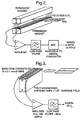
- Figure 3 illustrates a second embodiment of the invention which takes the form of a single-sided reader, the reader being suitable for reading magnetic elements down to about 1 mm in length with coercivities up to about 500 oersted.
- the sensitivity of the reader is approximately uniform over a range of 0 -1 mm from the surface of the coils, the maximum useable range being around 2 mm.
- the static magnetic fields are created by a fully-saturated sintered NdFe permanent magnet with dimensions 15 mm long x 5 mm wide x 10 mm thick and a surface field of c. 1.0 Tesla.
- the overall receiver coil is made from two anti-phase connected coils, i.e. as a figure-of-8 configuration. Each coil is wound on a former 1.6 mm wide x 10 mm long, and contains 70 pilewound turns of 0.1 mm diameter enamelled copper wire.
- This configuration provides good coupling to the magnetic dipole radiation from the tags, and also provides a rapid fall-off in sensitivity with distance from the coil. Such a sensitivity profile is desirable for operation in environments where significant external magnetic noise sources may be present (e.g. if the reader is part of a machine containing unshielded electric motors).
- the low-level output from the receiver coil is amplified x 1000 in a low-noise instrumentation amplifier, a device such as the Analogue Devices AMP-027 integrated circuit being suitable.
- the bandwidth of the system is defined by a low pass filter, implemented using well-known techniques based on low-cost operational amplifiers e.g. type TL084. The optimum signal-to-noise ratio is provided when the filter bandwidth matches the maximum signal bandwidth. For tags with magnetic elements of minimum length 1 mm, moving at speeds of 10 m/sec, a bandwidth of 5 Khz is appropriate.
- the tag illustrated in Figure 2 is shown with three magnetic elements; that of Figure 3 with four magnetic elements. It will be appreciated, from a consideration of Figs. 1(a) to 1(c), that the devices of Figs. 2 and 3 will read these tags, giving signals WHICH correspond in number to the number of magnetic elements present in the tag, and whose characteristics are dependent upon the length of the magnetic elements (compare Figs. 1(b) and 1(c)). The devices thus function as readers for the tags.
- a particularly advantageous arrangement comes from the use of a multi-layer printed circuit board or "PCB" (as commonly used for implementing electronic circuits), to construct the coils required in FN heads.
- PCB printed circuit board
- the patterns on such circuits are lithographically generated, allowing very precise coil geometries to be achieved and readily reproduced in volume manufacture.
- This form of construction allows very precise 'coil winding', and the production of a variety of specialised antennae can be envisaged which exploit the precise three dimensional tolerances that are achievable in multi-layer lithographic PCB production.
- the coil formation is realised in using particular geometries of tracks on each layer and subsequently connecting these using standard through-layer interconnection methods.
- scaling coils for different applications becomes very simple, and coil structures that would be difficult to achieve by conventional coil winding techniques becomes relatively straightforward.
- Fig 4 is an example of the technique. This shows the important physical parameters of one particular implementation of the scheme.
- Fig 4a we can see the basic concept of the delineation of metallic tracks (the equivalent of the wire in a conventional coil) as realised using lithographic means. These tracks are then interconnected to create a three dimensional coil, with the tracks on each layer forming the windings (Fig 4b).
- Fig 4b we have implemented coils employing over 20 PCB layers.
- Overlapping geometries can have advantages in particular applications. For example, a single balanced coil arrangement is unsuitable for detection over large areas because it becomes excessively sensitive to external interference. Covering the desired area with a number of smaller coils having overlapping detection regions overcomes this problem).
- Figure 5 shows one way in which this can be achieved, with coil patterns etched onto different layers of a multi-layer board.
- PCB construction is also inherently rigid, and this is beneficial in preventing movement of the coil windings with respect to the magnet. Any such movement, caused for example by accidental impacts on the head, would generate unwanted noise voltages in the coil, thus degrading performance.
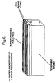
- a further design improvement is to extend the surface of the permanent magnet up through the centre of the coils. This increases the field strength and gradient field in the region of interest, and provides increased resolution or signal level, or both, compared to a design where the magnet surface is beneath the level of the coils.
- An implementation using a magnet with an extended pole piece is illustrated in Figure 6. This uses PCB coils, but could also be implemented with conventionally-wound coils.
Landscapes
- Life Sciences & Earth Sciences (AREA)
- Engineering & Computer Science (AREA)
- Physics & Mathematics (AREA)
- Remote Sensing (AREA)
- General Physics & Mathematics (AREA)
- Environmental & Geological Engineering (AREA)
- Geology (AREA)
- General Life Sciences & Earth Sciences (AREA)
- Electromagnetism (AREA)
- Geophysics (AREA)
- Geophysics And Detection Of Objects (AREA)
- Burglar Alarm Systems (AREA)
- Measuring Magnetic Variables (AREA)
- Inspection Of Paper Currency And Valuable Securities (AREA)
- Medicines Containing Antibodies Or Antigens For Use As Internal Diagnostic Agents (AREA)
- Magnetic Record Carriers (AREA)
- Holo Graphy (AREA)
Claims (10)
- Detektor zum Erfassen der Anwesenheit eines magnetischen Markers, der eine leicht magnetisierbare Achse aufweist, wobei der Detektor umfasst: 1) entweder i) einen Magneten oder ii) ein Paar Magnete, die magnetisch gegeneinander ausgerichtet sind, wobei der Magnet oder die Magnete so angeordnet sind, dass sie einen Raumbereich bestimmen, durch bzw. quer durch den der magnetische Marker bei Gebrauch geführt wird, so dass das entstehende Magnetfeldmuster einen ersten Bereich umfasst, in dem die Komponente des Magnetfelds bezüglich einer ersten Richtung null ist, und dass in an den ersten Bereich anschließenden Gebieten die Komponente des Magnetfelds bezüglich der ersten Richtung dazu ausreicht, den oder einen Teil des magnetischen Markers zu sättigen, und dass der Magnet oder die Magnete und das entstehende Magnetfeldmuster so beschaffen sind, dass ein Wechsel der Polarität der Magnetisierung des magnetischen Markers im Verlauf seines Durchgangs durch das Magnetfeld innerhalb des Raumbereichs bewirkt wird; und 2) Empfängerspulen, die ein Paar oder mehrere Paare Spulen in gegenphasiger Anordnung umfassen, wobei die Spulen über und nahe an einem Pol des Magneten angeordnet sind, falls ein Einzelmagnet eingesetzt wird, oder zwischen dem Magnetpaar angeordnet sind, falls zwei Magnete eingesetzt werden; und die Spulen so angeordnet sind, dass sie die magnetische Dipolstrahlung erfassen, die der magnetische Marker beim Durchgang durch das Magnetfeld aussendet, wobei die leicht magnetisierbare Achse des Markers in der Bewegungsrichtung orientiert ist.
- Detektor nach Anspruch 1, umfassend ein Paar Permanentmagnete, die magnetisch gegeneinander ausgerichtet sind, wobei der Raum zwischen den Magneten den Raumbereich bestimmt und die Form eines Schlitzes hat, durch den der magnetische Marker bei Gebrauch geführt wird.
- Detektor nach Anspruch 1, der einen einzelnen Permanentmagnet umfasst, wobei der Raumbereich von einem Bereich des Raums über einer Oberfläche des Magneten gebildet wird, und der magnetische Marker bei Gebrauch nahe an dem Magneten über dessen Oberfläche geführt wird.
- Detektor nach Anspruch 1, 2 oder 3, wobei die Empfängerspulen eine Anzahl miteinander verbundener Spulen umfassen, die in geometrisch überlappender Anordnung untergebracht sind.
- Detektor nach Anspruch 1, 2, 3 oder 4, wobei die Spulen die Form einer Gruppe von gedruckten Schaltungsplatinen haben und die Windungen durch leitende Pfade auf den Platinen gebildet werden, und die Platinen miteinander verbunden sind, so dass eine dreidimensionale Spule gebildet wird.
- Detektor nach irgendeinem vorhergehenden Anspruch, wobei der oder jeder Magnet einen Polschuh enthält, der zwischen den Windungen der Empfängerspule bzw. der Empfängerspulen verläuft.
- Detektor nach irgendeinem vorhergehenden Anspruch, zudem umfassend eine Signalverarbeitungsvorrichtung, die an die Empfängerspule angeschlossen ist.
- Detektor nach Anspruch 7, worin die Signalverarbeitungsvorrichtung so konfiguriert und eingerichtet ist, dass sie ein Ausgangssignal erzeugt, das der im magnetischen Marker gespeicherten Information entspricht oder damit korreliert ist.
- Detektor nach Anspruch 8, worin die Signalverarbeitungsvorrichtung einen rauscharmen Messverstärker enthält, dessen Eingänge mit der Empfängerspule bzw. den Empfängerspulen verbunden sind, und dessen Ausgang an ein Tiefpassfilter angeschlossen ist.
- Banknotenleser, umfassend einen Detektor nach irgendeinem vorhergehenden Anspruch.
Applications Claiming Priority (5)
| Application Number | Priority Date | Filing Date | Title |
|---|---|---|---|
| GBGB9612831.9A GB9612831D0 (en) | 1996-06-19 | 1996-06-19 | Spatial magnetic-interrogation |
| GB9612831 | 1996-06-19 | ||
| GBGB9620591.9A GB9620591D0 (en) | 1996-10-03 | 1996-10-03 | Magnetic interrogation techniques |
| GB9620591 | 1996-10-03 | ||
| PCT/GB1997/001662 WO1997048990A1 (en) | 1996-06-19 | 1997-06-19 | Magnetic reading devices |
Publications (2)
| Publication Number | Publication Date |
|---|---|
| EP0906583A1 EP0906583A1 (de) | 1999-04-07 |
| EP0906583B1 true EP0906583B1 (de) | 2003-08-27 |
Family
ID=26309540
Family Applications (1)
| Application Number | Title | Priority Date | Filing Date |
|---|---|---|---|
| EP97927276A Expired - Lifetime EP0906583B1 (de) | 1996-06-19 | 1997-06-19 | Magnetische lesevorrichtungen |
Country Status (11)
| Country | Link |
|---|---|
| US (1) | US6230972B1 (de) |
| EP (1) | EP0906583B1 (de) |
| JP (1) | JP2000512784A (de) |
| CN (1) | CN1137392C (de) |
| AT (1) | ATE248377T1 (de) |
| AU (1) | AU717499B2 (de) |
| BR (1) | BR9709864A (de) |
| CA (1) | CA2258772C (de) |
| DE (1) | DE69724426T2 (de) |
| RU (1) | RU2180129C2 (de) |
| WO (1) | WO1997048990A1 (de) |
Families Citing this family (28)
| Publication number | Priority date | Publication date | Assignee | Title |
|---|---|---|---|---|
| US6075441A (en) | 1996-09-05 | 2000-06-13 | Key-Trak, Inc. | Inventoriable-object control and tracking system |
| GB9806923D0 (en) * | 1998-03-31 | 1998-05-27 | Flying Null Ltd | Position sensing |
| CA2343412A1 (en) | 1998-09-11 | 2000-03-23 | William C. Maloney | Object control and tracking system with zonal transition detection |
| US6232876B1 (en) | 1998-09-11 | 2001-05-15 | Key-Trak, Inc. | Mobile object tracking system |
| AU5916799A (en) | 1998-09-11 | 2000-04-03 | Key-Trak, Inc. | Object tracking system with non-contact object detection and identification |
| US6195005B1 (en) | 1998-09-11 | 2001-02-27 | Key-Trak, Inc. | Object carriers for an object control and tracking system |
| US6891473B2 (en) | 1998-09-11 | 2005-05-10 | Key-Trak, Inc. | Object carriers and lighted tags for an object control and tracking system |
| AU5924599A (en) | 1998-09-11 | 2000-04-03 | Key-Trak, Inc. | Tamper detection and prevention for an object control and tracking system |
| WO2000039611A1 (en) * | 1998-12-23 | 2000-07-06 | Flying Null Limited | Reading devices for magnetic tags |
| GB2346037B (en) * | 1999-01-13 | 2001-06-20 | Flying Null Ltd | Shielded magnetic reading devices |
| IL132499A0 (en) * | 1999-10-21 | 2001-03-19 | Advanced Coding Systems Ltd | A security system for protecting various items and a method for reading a code pattern |
| US6452380B1 (en) * | 2000-03-23 | 2002-09-17 | Lexmark International, Inc. | Rod and apparatus for calibrating magnetic roll testing apparatus |
| US7352771B2 (en) * | 2002-10-08 | 2008-04-01 | Colder Products Company | Data collision detection device and method |
| SE529125C2 (sv) * | 2005-03-02 | 2007-05-08 | Tetra Laval Holdings & Finance | Sätt och anordning för att bestämma läget hos ett förpackningsmaterial med magnetiska markeringar |
| GB0519971D0 (en) * | 2005-09-30 | 2005-11-09 | Rue De Int Ltd | Method and apparatus for detecting a magnetic feature on an article |
| US20070260345A1 (en) * | 2006-04-14 | 2007-11-08 | Mifsud Vincent D | Component manufacturing system for a prefabricated building panel |
| US9168104B2 (en) * | 2008-06-23 | 2015-10-27 | John Richard Dein | Intra-operative system for identifying and tracking surgical sharp objects, instruments, and sponges |
| DE102009003815A1 (de) * | 2009-04-22 | 2010-10-28 | Wincor Nixdorf International Gmbh | Selbstbedienungsgerät |
| US9203546B1 (en) * | 2014-06-04 | 2015-12-01 | Square, Inc. | Magnetic stripe reader tamper protection |
| US10775452B2 (en) | 2016-07-12 | 2020-09-15 | Magnetic Insight, Inc. | Magnetic particle imaging |
| WO2018023049A1 (en) | 2016-07-28 | 2018-02-01 | Sun Nuclear Corporation | Beam angle direction determination |
| US10192076B1 (en) | 2016-08-29 | 2019-01-29 | Square, Inc. | Security housing with recesses for tamper localization |
| US10251260B1 (en) | 2016-08-29 | 2019-04-02 | Square, Inc. | Circuit board to hold connector pieces for tamper detection circuit |
| US10595400B1 (en) | 2016-09-30 | 2020-03-17 | Square, Inc. | Tamper detection system |
| US10504096B1 (en) | 2017-04-28 | 2019-12-10 | Square, Inc. | Tamper detection using ITO touch screen traces |
| JP2020531076A (ja) | 2017-08-16 | 2020-11-05 | ザ リージェンツ オブ ザ ユニバーシティ オブ カリフォルニア | パルス磁気粒子イメージングシステム及び方法 |
| EP3563183B1 (de) * | 2017-11-30 | 2020-09-30 | Sub Service Srl | Nichtmagnetische hohlstange mit magnetischer sonde zur detektion von nichtexplodierten kampfmitteln unter wasser |
| WO2020186185A1 (en) | 2019-03-13 | 2020-09-17 | Magnetic Insight, Inc. | Magnetic particle actuation |
Family Cites Families (15)
| Publication number | Priority date | Publication date | Assignee | Title |
|---|---|---|---|---|
| US3919704A (en) | 1972-12-04 | 1975-11-11 | Check Mate Systems Inc | System and method for detecting unauthorized removal of goods from protected premises, and magnet detecting apparatus suitable for use therein |
| US3964042A (en) | 1973-06-25 | 1976-06-15 | Sperry Rand Corporation | Static magnetic field metal detector |
| FI62910C (fi) * | 1979-12-05 | 1983-03-10 | Outokumpu Oy | Anordning foer detektering av magnetiskt ledande metaller i enoerlig materialstroem |
| SU1270780A1 (ru) * | 1982-12-23 | 1986-11-15 | Конструкторское Бюро Главного Управления Сигнализации И Связи Мпс | Устройство дл считывани информации с подвижных объектов |
| JPS6029683A (ja) * | 1983-07-27 | 1985-02-15 | Sigma Gijutsu Kogyo Kk | 磁気センサ |
| CA1234892A (en) * | 1984-02-16 | 1988-04-05 | Pierre Taillefer | Security tag detection system |
| EP0295085B1 (de) * | 1987-06-08 | 1996-11-06 | Esselte Meto International GmbH | Magnetische Vorrichtungen verwendende Artikelermittlung und/oder -identifizierung |
| GB8800879D0 (en) * | 1988-01-15 | 1988-02-17 | Scient Generics Ltd | Location system |
| JPH0352425A (ja) | 1989-07-20 | 1991-03-06 | Fujitsu General Ltd | リモコン光信号受信方法 |
| RU2015559C1 (ru) * | 1992-05-14 | 1994-06-30 | Игорь Георгиевич Ястребов | Кодирующее устройство |
| US5397985A (en) | 1993-02-09 | 1995-03-14 | Mobil Oil Corporation | Method for the imaging of casing morphology by twice integrating magnetic flux density signals |
| US5594229A (en) * | 1993-07-12 | 1997-01-14 | Nhk Spring Co., Ltd. | Method and apparatus for checking the authenticity of a checking object by detecting magnetic flux reversals |
| JPH08135866A (ja) | 1994-11-15 | 1996-05-31 | Osaka Gas Co Ltd | 柔軟管接続継手 |
| ES2150460T3 (es) | 1994-11-17 | 2000-12-01 | Minnesota Mining & Mfg | Sistema de identificacion remota. |
| JP3631540B2 (ja) * | 1995-11-28 | 2005-03-23 | スター精密株式会社 | 磁気表示消去装置 |
-
1997
- 1997-06-19 WO PCT/GB1997/001662 patent/WO1997048990A1/en not_active Ceased
- 1997-06-19 CA CA002258772A patent/CA2258772C/en not_active Expired - Fee Related
- 1997-06-19 US US09/202,631 patent/US6230972B1/en not_active Expired - Fee Related
- 1997-06-19 DE DE69724426T patent/DE69724426T2/de not_active Expired - Fee Related
- 1997-06-19 BR BR9709864-7A patent/BR9709864A/pt not_active IP Right Cessation
- 1997-06-19 CN CNB971963746A patent/CN1137392C/zh not_active Expired - Fee Related
- 1997-06-19 AT AT97927276T patent/ATE248377T1/de not_active IP Right Cessation
- 1997-06-19 JP JP10502521A patent/JP2000512784A/ja not_active Ceased
- 1997-06-19 RU RU99101083/28A patent/RU2180129C2/ru not_active IP Right Cessation
- 1997-06-19 AU AU31827/97A patent/AU717499B2/en not_active Ceased
- 1997-06-19 EP EP97927276A patent/EP0906583B1/de not_active Expired - Lifetime
Also Published As
| Publication number | Publication date |
|---|---|
| CA2258772C (en) | 2004-05-04 |
| JP2000512784A (ja) | 2000-09-26 |
| DE69724426D1 (de) | 2003-10-02 |
| CA2258772A1 (en) | 1997-12-24 |
| DE69724426T2 (de) | 2004-03-18 |
| US6230972B1 (en) | 2001-05-15 |
| AU3182797A (en) | 1998-01-07 |
| CN1225176A (zh) | 1999-08-04 |
| RU2180129C2 (ru) | 2002-02-27 |
| AU717499B2 (en) | 2000-03-30 |
| CN1137392C (zh) | 2004-02-04 |
| EP0906583A1 (de) | 1999-04-07 |
| WO1997048990A1 (en) | 1997-12-24 |
| BR9709864A (pt) | 2000-01-11 |
| ATE248377T1 (de) | 2003-09-15 |
Similar Documents
| Publication | Publication Date | Title |
|---|---|---|
| EP0906583B1 (de) | Magnetische lesevorrichtungen | |
| US4413254A (en) | Combined radio and magnetic energy responsive surveillance marker and system | |
| CA1256487A (en) | Method and apparatus for target reactivation | |
| US6369965B1 (en) | Magnetic interrogation techniques | |
| RU99101083A (ru) | Детектор для обнаружения присутствия магнитной метки | |
| US6060988A (en) | EAS marker deactivation device having core-wound energized coils | |
| EP1039412A1 (de) | Fern-Identifikationssystem | |
| US5552589A (en) | Permanent magnet assembly with MR element for detection/authentication of magnetic documents | |
| GB2314418A (en) | Sensing the presence of a magnetic tag | |
| EP1145048B1 (de) | Lesevorrichtungen für magnetische etiketten | |
| KR20060038997A (ko) | 자계 검출용 안테나, 및 그 안테나를 사용한 검지 태그검출용 게이트 | |
| US4862303A (en) | Magnetic instrument for reading telegraphic signals | |
| KR100484009B1 (ko) | 자기감지및판독장치 | |
| GB2328281A (en) | Magnetic reading devices | |
| JP3774501B2 (ja) | 磁気マーカおよびその読取方法 | |
| EP0342062A2 (de) | Erkennung von mit magnetisierbarer Tinte gedruckten Mustern | |
| US20070268141A1 (en) | Magnetic Tagging | |
| GB2346037A (en) | Shielded magnetic reading devices | |
| JPH04195811A (ja) | 磁気イメージセンサ | |
| JPH0731082U (ja) | パチンコ玉検出用磁気センサ | |
| KR20010083887A (ko) | 물체 감시 시스템용 원거리장 자석 재감응 장치 | |
| PL113998B3 (en) | Contactless rail-mounted detector especially for electronic counters utilized for counting axles |
Legal Events
| Date | Code | Title | Description |
|---|---|---|---|
| PUAI | Public reference made under article 153(3) epc to a published international application that has entered the european phase |
Free format text: ORIGINAL CODE: 0009012 |
|
| 17P | Request for examination filed |
Effective date: 19990111 |
|
| AK | Designated contracting states |
Kind code of ref document: A1 Designated state(s): AT BE CH DE DK ES FI FR GB GR IE IT LI LU MC NL PT SE |
|
| AX | Request for extension of the european patent |
Free format text: AL PAYMENT 990111;LT PAYMENT 990111;LV PAYMENT 990111;RO PAYMENT 990111;SI PAYMENT 990111 |
|
| 17Q | First examination report despatched |
Effective date: 20020301 |
|
| GRAH | Despatch of communication of intention to grant a patent |
Free format text: ORIGINAL CODE: EPIDOS IGRA |
|
| RBV | Designated contracting states (corrected) |
Designated state(s): AT BE CH DE DK ES FI FR GR IE IT LI LU MC NL PT SE |
|
| GRAH | Despatch of communication of intention to grant a patent |
Free format text: ORIGINAL CODE: EPIDOS IGRA |
|
| GRAA | (expected) grant |
Free format text: ORIGINAL CODE: 0009210 |
|
| AK | Designated contracting states |
Designated state(s): AT BE CH DE DK ES FI FR GR IE IT LI LU MC NL PT SE |
|
| AX | Request for extension of the european patent |
Extension state: AL LT LV RO SI |
|
| PG25 | Lapsed in a contracting state [announced via postgrant information from national office to epo] |
Ref country code: NL Free format text: LAPSE BECAUSE OF FAILURE TO SUBMIT A TRANSLATION OF THE DESCRIPTION OR TO PAY THE FEE WITHIN THE PRESCRIBED TIME-LIMIT Effective date: 20030827 Ref country code: IT Free format text: LAPSE BECAUSE OF FAILURE TO SUBMIT A TRANSLATION OF THE DESCRIPTION OR TO PAY THE FEE WITHIN THE PRE;WARNING: LAPSES OF ITALIAN PATENTS WITH EFFECTIVE DATE BEFORE 2007 MAY HAVE OCCURRED AT ANY TIME BEFORE 2007. THE CORRECT EFFECTIVE DATE MAY BE DIFFERENT FROM THE ONE RECORDED.SCRIBED TIME-LIMIT Effective date: 20030827 Ref country code: FI Free format text: LAPSE BECAUSE OF FAILURE TO SUBMIT A TRANSLATION OF THE DESCRIPTION OR TO PAY THE FEE WITHIN THE PRESCRIBED TIME-LIMIT Effective date: 20030827 |
|
| REG | Reference to a national code |
Ref country code: CH Ref legal event code: EP |
|
| REG | Reference to a national code |
Ref country code: IE Ref legal event code: FG4D |
|
| REF | Corresponds to: |
Ref document number: 69724426 Country of ref document: DE Date of ref document: 20031002 Kind code of ref document: P |
|
| REG | Reference to a national code |
Ref country code: CH Ref legal event code: NV Representative=s name: DR. LUSUARDI AG |
|
| PG25 | Lapsed in a contracting state [announced via postgrant information from national office to epo] |
Ref country code: SE Free format text: LAPSE BECAUSE OF FAILURE TO SUBMIT A TRANSLATION OF THE DESCRIPTION OR TO PAY THE FEE WITHIN THE PRESCRIBED TIME-LIMIT Effective date: 20031127 Ref country code: GR Free format text: LAPSE BECAUSE OF FAILURE TO SUBMIT A TRANSLATION OF THE DESCRIPTION OR TO PAY THE FEE WITHIN THE PRESCRIBED TIME-LIMIT Effective date: 20031127 Ref country code: DK Free format text: LAPSE BECAUSE OF FAILURE TO SUBMIT A TRANSLATION OF THE DESCRIPTION OR TO PAY THE FEE WITHIN THE PRESCRIBED TIME-LIMIT Effective date: 20031127 |
|
| PG25 | Lapsed in a contracting state [announced via postgrant information from national office to epo] |
Ref country code: ES Free format text: LAPSE BECAUSE OF FAILURE TO SUBMIT A TRANSLATION OF THE DESCRIPTION OR TO PAY THE FEE WITHIN THE PRESCRIBED TIME-LIMIT Effective date: 20031208 |
|
| PG25 | Lapsed in a contracting state [announced via postgrant information from national office to epo] |
Ref country code: PT Free format text: LAPSE BECAUSE OF FAILURE TO SUBMIT A TRANSLATION OF THE DESCRIPTION OR TO PAY THE FEE WITHIN THE PRESCRIBED TIME-LIMIT Effective date: 20040127 |
|
| NLV1 | Nl: lapsed or annulled due to failure to fulfill the requirements of art. 29p and 29m of the patents act | ||
| LTIE | Lt: invalidation of european patent or patent extension |
Effective date: 20030827 |
|
| ET | Fr: translation filed | ||
| PG25 | Lapsed in a contracting state [announced via postgrant information from national office to epo] |
Ref country code: MC Free format text: LAPSE BECAUSE OF NON-PAYMENT OF DUE FEES Effective date: 20040630 |
|
| PLBE | No opposition filed within time limit |
Free format text: ORIGINAL CODE: 0009261 |
|
| STAA | Information on the status of an ep patent application or granted ep patent |
Free format text: STATUS: NO OPPOSITION FILED WITHIN TIME LIMIT |
|
| 26N | No opposition filed |
Effective date: 20040528 |
|
| PGFP | Annual fee paid to national office [announced via postgrant information from national office to epo] |
Ref country code: IE Payment date: 20050516 Year of fee payment: 9 |
|
| PGFP | Annual fee paid to national office [announced via postgrant information from national office to epo] |
Ref country code: AT Payment date: 20050524 Year of fee payment: 9 |
|
| PGFP | Annual fee paid to national office [announced via postgrant information from national office to epo] |
Ref country code: BE Payment date: 20050603 Year of fee payment: 9 |
|
| PGFP | Annual fee paid to national office [announced via postgrant information from national office to epo] |
Ref country code: FR Payment date: 20050627 Year of fee payment: 9 Ref country code: CH Payment date: 20050627 Year of fee payment: 9 Ref country code: LU Payment date: 20050627 Year of fee payment: 9 |
|
| PGFP | Annual fee paid to national office [announced via postgrant information from national office to epo] |
Ref country code: DE Payment date: 20050629 Year of fee payment: 9 |
|
| PG25 | Lapsed in a contracting state [announced via postgrant information from national office to epo] |
Ref country code: IE Free format text: LAPSE BECAUSE OF NON-PAYMENT OF DUE FEES Effective date: 20060619 Ref country code: AT Free format text: LAPSE BECAUSE OF NON-PAYMENT OF DUE FEES Effective date: 20060619 |
|
| PG25 | Lapsed in a contracting state [announced via postgrant information from national office to epo] |
Ref country code: LI Free format text: LAPSE BECAUSE OF NON-PAYMENT OF DUE FEES Effective date: 20060630 Ref country code: CH Free format text: LAPSE BECAUSE OF NON-PAYMENT OF DUE FEES Effective date: 20060630 Ref country code: BE Free format text: LAPSE BECAUSE OF NON-PAYMENT OF DUE FEES Effective date: 20060630 |
|
| PG25 | Lapsed in a contracting state [announced via postgrant information from national office to epo] |
Ref country code: DE Free format text: LAPSE BECAUSE OF NON-PAYMENT OF DUE FEES Effective date: 20070103 |
|
| REG | Reference to a national code |
Ref country code: CH Ref legal event code: PL |
|
| REG | Reference to a national code |
Ref country code: IE Ref legal event code: MM4A |
|
| REG | Reference to a national code |
Ref country code: FR Ref legal event code: ST Effective date: 20070228 |
|
| BERE | Be: lapsed |
Owner name: *FLYING NULL LTD Effective date: 20060630 |
|
| PG25 | Lapsed in a contracting state [announced via postgrant information from national office to epo] |
Ref country code: FR Free format text: LAPSE BECAUSE OF NON-PAYMENT OF DUE FEES Effective date: 20060630 |
|
| PG25 | Lapsed in a contracting state [announced via postgrant information from national office to epo] |
Ref country code: LU Free format text: LAPSE BECAUSE OF NON-PAYMENT OF DUE FEES Effective date: 20060619 |