EP0906503B1 - Fuel-air mixture apparatus - Google Patents
Fuel-air mixture apparatus Download PDFInfo
- Publication number
- EP0906503B1 EP0906503B1 EP97925247A EP97925247A EP0906503B1 EP 0906503 B1 EP0906503 B1 EP 0906503B1 EP 97925247 A EP97925247 A EP 97925247A EP 97925247 A EP97925247 A EP 97925247A EP 0906503 B1 EP0906503 B1 EP 0906503B1
- Authority
- EP
- European Patent Office
- Prior art keywords
- fuel
- air
- air passage
- nozzle
- needle
- Prior art date
- Legal status (The legal status is an assumption and is not a legal conclusion. Google has not performed a legal analysis and makes no representation as to the accuracy of the status listed.)
- Expired - Lifetime
Links
- 239000000203 mixture Substances 0.000 title claims description 34
- 239000000446 fuel Substances 0.000 claims description 60
- 230000001939 inductive effect Effects 0.000 claims description 7
- 238000002485 combustion reaction Methods 0.000 claims description 4
- 238000011144 upstream manufacturing Methods 0.000 claims description 4
- 230000015572 biosynthetic process Effects 0.000 claims description 3
- 238000013459 approach Methods 0.000 claims description 2
- 239000011324 bead Substances 0.000 claims description 2
- 230000000994 depressogenic effect Effects 0.000 claims description 2
- 238000005086 pumping Methods 0.000 claims description 2
- 238000009834 vaporization Methods 0.000 description 5
- 238000005553 drilling Methods 0.000 description 4
- 239000011800 void material Substances 0.000 description 3
- 230000006698 induction Effects 0.000 description 2
- 239000007788 liquid Substances 0.000 description 2
- 230000006978 adaptation Effects 0.000 description 1
- 230000006835 compression Effects 0.000 description 1
- 238000007906 compression Methods 0.000 description 1
- 230000001276 controlling effect Effects 0.000 description 1
- 230000000694 effects Effects 0.000 description 1
- 210000004907 gland Anatomy 0.000 description 1
- 238000002347 injection Methods 0.000 description 1
- 239000007924 injection Substances 0.000 description 1
- 230000001105 regulatory effect Effects 0.000 description 1
- 238000007789 sealing Methods 0.000 description 1
Images

Classifications
-
- F—MECHANICAL ENGINEERING; LIGHTING; HEATING; WEAPONS; BLASTING
- F02—COMBUSTION ENGINES; HOT-GAS OR COMBUSTION-PRODUCT ENGINE PLANTS
- F02M—SUPPLYING COMBUSTION ENGINES IN GENERAL WITH COMBUSTIBLE MIXTURES OR CONSTITUENTS THEREOF
- F02M3/00—Idling devices for carburettors
- F02M3/08—Other details of idling devices
- F02M3/10—Fuel metering pins; Nozzles
-
- F—MECHANICAL ENGINEERING; LIGHTING; HEATING; WEAPONS; BLASTING
- F02—COMBUSTION ENGINES; HOT-GAS OR COMBUSTION-PRODUCT ENGINE PLANTS
- F02M—SUPPLYING COMBUSTION ENGINES IN GENERAL WITH COMBUSTIBLE MIXTURES OR CONSTITUENTS THEREOF
- F02M7/00—Carburettors with means for influencing, e.g. enriching or keeping constant, fuel/air ratio of charge under varying conditions
- F02M7/12—Other installations, with moving parts, for influencing fuel/air ratio, e.g. having valves
- F02M7/22—Other installations, with moving parts, for influencing fuel/air ratio, e.g. having valves fuel flow cross-sectional area being controlled dependent on air-throttle-valve position
-
- Y—GENERAL TAGGING OF NEW TECHNOLOGICAL DEVELOPMENTS; GENERAL TAGGING OF CROSS-SECTIONAL TECHNOLOGIES SPANNING OVER SEVERAL SECTIONS OF THE IPC; TECHNICAL SUBJECTS COVERED BY FORMER USPC CROSS-REFERENCE ART COLLECTIONS [XRACs] AND DIGESTS
- Y10—TECHNICAL SUBJECTS COVERED BY FORMER USPC
- Y10S—TECHNICAL SUBJECTS COVERED BY FORMER USPC CROSS-REFERENCE ART COLLECTIONS [XRACs] AND DIGESTS
- Y10S261/00—Gas and liquid contact apparatus
- Y10S261/01—Auxiliary air inlet carburetors
-
- Y—GENERAL TAGGING OF NEW TECHNOLOGICAL DEVELOPMENTS; GENERAL TAGGING OF CROSS-SECTIONAL TECHNOLOGIES SPANNING OVER SEVERAL SECTIONS OF THE IPC; TECHNICAL SUBJECTS COVERED BY FORMER USPC CROSS-REFERENCE ART COLLECTIONS [XRACs] AND DIGESTS
- Y10—TECHNICAL SUBJECTS COVERED BY FORMER USPC
- Y10S—TECHNICAL SUBJECTS COVERED BY FORMER USPC CROSS-REFERENCE ART COLLECTIONS [XRACs] AND DIGESTS
- Y10S261/00—Gas and liquid contact apparatus
- Y10S261/38—Needle valves
-
- Y—GENERAL TAGGING OF NEW TECHNOLOGICAL DEVELOPMENTS; GENERAL TAGGING OF CROSS-SECTIONAL TECHNOLOGIES SPANNING OVER SEVERAL SECTIONS OF THE IPC; TECHNICAL SUBJECTS COVERED BY FORMER USPC CROSS-REFERENCE ART COLLECTIONS [XRACs] AND DIGESTS
- Y10—TECHNICAL SUBJECTS COVERED BY FORMER USPC
- Y10S—TECHNICAL SUBJECTS COVERED BY FORMER USPC CROSS-REFERENCE ART COLLECTIONS [XRACs] AND DIGESTS
- Y10S261/00—Gas and liquid contact apparatus
- Y10S261/48—Sonic vibrators
Definitions
- the present invention relates to a fuel-air mixture apparatus, particularly for an internal combustion engine.
- Fuel-air mixture apparatuses of the type where fuel is mixed with air prior to induction into the cylinder(s) of an engine generally rely on a pressure reduction at a throttle in the device to draw fuel into the device, in which case the device is known as a carburettor, or rely on fuel injection into the air as it passes through the device.
- the prior devices rely on a single stage of mixture of fuel and air and are limited as regards the droplet size and total vaporisation of the fuel in the air which they induce. Inadequate vaporisation and too large a droplet size result in unburned and/or incompletely burnt fuel being present in the exhaust from the engine.
- the object of the present invention is to provide a fuel-air mixture apparatus which causes low quantities of unburned and incompletely burnt fuel to be present in the exhaust.
- the needle has a small bead, preferably a small ball or invert cone, at its tip for inducing divergence of the fuel as it flows from the end of the needle and/or for discouraging fuel flow to the point of the needle and linear drop formation from the point.
- a small bead preferably a small ball or invert cone
- the inlet of the primary air passage will be connected to an air cleaner and the outlet will be connected to an inlet manifold of an internal combustion engine.
- the inlet of the secondary air passage can be from the primary air passage between its inlet and its throttle.
- the inlets to the two air passages can be independent of each other, but normally downstream of the same air cleaner.
- the outlet of the secondary air passage may be provided at a fixed throat in the primary air passage, to induce increased air flow speed in the primary passage and reduced pressure at the outlet of the secondary air passage for enhanced air flow in the secondary air passage.
- a plurality of outlets from the secondary air passage are provided at the fixed throat.
- the secondary air passage has a branch surrounding the primary air passage, the said outlets being from the branch and spaced around the primary air passage.
- the secondary air passage is provided with a constriction for inducing increased air flow speed therethrough and the nozzle is arranged at the constriction whereby the fuel is mixed with the air at its region of increased flow speed.
- the constriction can be formed as an annular space between the nozzle or the needle and a ring.
- the ring has up- and down-stream bevels meeting at an edge for inducing turbulence.
- the secondary air passage is provided with a chamber, with the nozzle being arranged to inject fuel into the chamber for initial fuel-air mixing in the chamber.
- the passage may have a constriction at the upstream and/or downstream ends of the chamber. When at the downstream end, the constriction can be at the outlet from the secondary air passage to the primary air passage.
- the constriction(s) is/are preferably configured to induce turbulence in the air flow in the secondary air passage, to enhance the mixing of the fuel with the air, suitably by forming the constriction with a pair of bevels meeting at an edge.
- the portion of the secondary air passage upstream of the chamber may approach the chamber at least substantially tangentially thereto, so as to induce swirling of the air flow in the chamber.
- the nozzle is preferably arranged to introduce the fuel at the centre of the swirl, whence it can radiate for mixing with the air.
- the nozzle is so arranged that the fuel leaving its orifice impinges on an ultrasonic transducer for comminution of the fuel into small droplets.
- fuel flow from the nozzle may be induced by depressed pressure in the device at the nozzle's orifice; normally a pump will be provided for pumping fuel will be pumped to the nozzle.
- the pump will be adapted to deliver fuel to the nozzle at substantially constant pressure.
- the fuel may be gaseous or liquid.
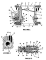
- the fuel-air mixture apparatus 1 has a body 2 adapted for connection via a flange 3 to an air cleaner housing 3' (only partially shown) and via a spigot 4 to an engine inlet manifold 4' (again only partially shown).
- a primary air passage 5 having an inlet 6, an adjustable throttle 7, a throat 8 and an outlet 9.
- the throttle will be connected in use to a speed control device for the engine (not shown), typically an accelerator pedal of a car or a governor, via a linkage 10.
- the throat is provided in a tubular insert 11, with the internal diameter of the throat chosen to match the size of the engine to which the device 1 is fitted. Where the throat is smaller than that shown in Figure 1, the tubular insert may have an upper extension as far as the throttle 7, which is provided with a smaller butterfly 12 to suit.
- a secondary air passage 13 having an inlet 14 from the air cleaner housing and an outlet 15 to the primary air passage 5. This is at the throat 8 and will be described in more detail below.
- the secondary air passage opens into a chamber 16, with the opening 17 being arranged tangentially to the chamber to induce swirling air flow in the chamber.
- the outlet 15 is provided axially of the chamber.
- a nozzle device 21 At the other end of the chamber, in a bore 18 in the body a nozzle device 21 is provided. It comprises a main sleeve 22 having two O-ring grooves 23 for O-rings 23' sealing a circumferential void 24 to the body. This void has a fuel supply bore 25 in the body 2 and connected to a continuous fuel pump (not shown) opening into it. A fuel inlet 26 leads from the void to an internal bore in the sleeve 22. Slidably mounted in the sleeve is a guide 27, sealed to the sleeve via a gland 28. The outside end of the guide carries a compression spring 29 and the end of the guide is closed by a plug 30 providing an abutment for the spring, whereby the guide is urged outwards.
- the guide has a bore 31 in which a needle 32 is slidably mounted.
- a spring 33 acts between the plug 30 and a washer 34 acting on an O-ring 34' abutting a head 35 of the needle.
- the latter has a point 36, carrying a small ball 37, which extends through a gauged aperture 38 in the end of the sleeve 22.
- the plug 30 is acted on by an abutment member 40, which is movable in step with the throttle 7 via a branch of the linkage 10.
- the arrangement is such that as the throttle 7 is progressively opened, the abutment member is progressively withdrawn to withdraw the needle point 36 from the aperture 38. This allows more fuel to flow through the bore 25, inlet 26 and aperture 38.
- the linkage is designed to ensure that the stoichometricly required amount of fuel is provided for the throttle opening.
- the fuel is induced to leave the needle point 36 at the ball 37 in small droplets, which enhances vaporisation of the fuel.
- This flow is also turbulent downstream of the throttle 7.
- the result is thorough mixing of the fuel and the air prior to induction into the engine. It should be noted that the fuel flows continuously from the nozzle device and mixes continuously with first the secondary air flow and then the primary air flow.
- the second embodiment there shown differs from the first embodiment in not having a chamber in its secondary air passage 213. Rather its nozzle device 221 incorporates a nose 261 mounted with the device in the bore 218 in the body 202.
- the nose has a lateral inlet 262 for the secondary air flow which impinges on a tip 263 of the needle sleeve 222 and is accelerated as it flows through a tapered outlet 264 of the nose.
- This outlet has a further taper 265 back-to-back with the taper 264, forming a constriction 266, causing the secondary air to be turbulent on leaving the nose.
- the constriction is arranged to be the outlet of the secondary air passage.
- the fuel introduction orifice, between the nozzle 221 and the needle 232 is close to the constriction, with the needle actually extending into the constriction.
- the arrangement induces fine fuel droplet formation and vaporisation of the fuel in the secondary air as it mixes with the primary air flow.
- the engine management computer can incorporate additional features, allowing adaptation of the apparatus to the type of fuel, grade of fuel and style of driving of the vehicle in which the apparatus is installed.
- the invention find application other than in internal combustion engines. It may for instance be used in boilers.
- the nozzle device can be arranged tangentially to the primary air passage.
- the secondary air passage can have two branches leading to two chambers.
- the first chamber, to which the first branch leads, is similar to that in the first embodiment, in that it accommodates the needle.
- the latter can have a small invert cone at its end. The cone is arranged to provide a sharp edge from which fuel droplets shed into the air-stream through the constriction.
- the second chamber is fed with air from the second branch.
- the two secondary air-streams meet in the region of a sonde of an ultrasonic transducer.
- the fuel droplets from the needle impinge on the sonde and are comminuted.
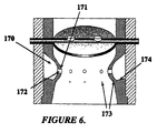
- the secondary air flow with the fuel leaves the second chamber and enters an annular passage behind a fixed throttle insert in the primary air passage.
- the insert has two series of drillings equi-angularly spaced around it. Upper ones of these are at smallest diameter section of the throttle and convey the bulk of the secondary air flow into the primary air flow through the throttle.
- the lower drillings are drains from a groove at the back of the insert, the groove being downwardly directed to drain any fuel liquid, which may accumulate therein, into the primary air passage.
Landscapes
- Engineering & Computer Science (AREA)
- Chemical & Material Sciences (AREA)
- Combustion & Propulsion (AREA)
- Mechanical Engineering (AREA)
- General Engineering & Computer Science (AREA)
- Fuel-Injection Apparatus (AREA)
- Control Of The Air-Fuel Ratio Of Carburetors (AREA)
- Nozzles (AREA)
Applications Claiming Priority (3)
| Application Number | Priority Date | Filing Date | Title |
|---|---|---|---|
| GB9612971 | 1996-06-20 | ||
| GBGB9612971.3A GB9612971D0 (en) | 1996-06-20 | 1996-06-20 | Fuel-air mixture apparatus |
| PCT/IB1997/000781 WO1997048897A1 (en) | 1996-06-20 | 1997-06-16 | Fuel-air mixture apparatus |
Publications (2)
| Publication Number | Publication Date |
|---|---|
| EP0906503A1 EP0906503A1 (en) | 1999-04-07 |
| EP0906503B1 true EP0906503B1 (en) | 2005-01-05 |
Family
ID=10795638
Family Applications (1)
| Application Number | Title | Priority Date | Filing Date |
|---|---|---|---|
| EP97925247A Expired - Lifetime EP0906503B1 (en) | 1996-06-20 | 1997-06-16 | Fuel-air mixture apparatus |
Country Status (13)
| Country | Link |
|---|---|
| US (1) | US6283460B1 (enExample) |
| EP (1) | EP0906503B1 (enExample) |
| JP (1) | JP2000512711A (enExample) |
| CN (1) | CN1096556C (enExample) |
| AU (1) | AU3045097A (enExample) |
| BR (1) | BR9709590A (enExample) |
| CA (1) | CA2258246C (enExample) |
| CZ (1) | CZ296645B6 (enExample) |
| DE (1) | DE69732182T2 (enExample) |
| ES (1) | ES2236809T3 (enExample) |
| GB (2) | GB9612971D0 (enExample) |
| RU (1) | RU2179652C2 (enExample) |
| WO (1) | WO1997048897A1 (enExample) |
Families Citing this family (23)
| Publication number | Priority date | Publication date | Assignee | Title |
|---|---|---|---|---|
| GB9814100D0 (en) * | 1998-07-01 | 1998-08-26 | Emarsson Kristjsn Bjorn | Fuel-air mixture apparatus |
| US6540210B2 (en) * | 1998-08-07 | 2003-04-01 | John R. Satterfield | Fluid emulsification systems and methods |
| JP2002266705A (ja) * | 2001-03-08 | 2002-09-18 | Zama Japan Kk | 膜式気化器 |
| US6736376B1 (en) * | 2002-03-19 | 2004-05-18 | Delisle Gilles L. | Anti-detonation fuel delivery system |
| US7513489B2 (en) * | 2003-03-19 | 2009-04-07 | Delisle Gilles L | Anti-detonation fuel delivery system |
| CA2519355A1 (en) * | 2003-03-19 | 2004-11-04 | Better Burn, Llc | Anti-detonation fuel delivery system |
| US7287742B2 (en) * | 2003-04-03 | 2007-10-30 | Walbro Engine Management, L.L.C. | Carburetor and method of manufacturing |
| US20050062177A1 (en) * | 2003-09-19 | 2005-03-24 | Zama Japan | Compression wave injection carburetor |
| US6868830B1 (en) * | 2004-05-14 | 2005-03-22 | James Meyer Aspen Engineering Services, Llc | Venturi induction for internal combustion engines |
| US7380772B1 (en) * | 2006-11-01 | 2008-06-03 | Walbro Engine Management, L.L.C. | Charge forming device with controlled air bypass |
| GB0710104D0 (en) | 2007-05-25 | 2007-07-04 | Fjoelblendir Ltd | Carburettors |
| US20090044787A1 (en) * | 2007-08-15 | 2009-02-19 | Adams Georg B L | Efficient Reduced-Emissions Carburetor |
| US8005603B2 (en) * | 2007-09-27 | 2011-08-23 | Continental Controls Corporation | Fuel control system and method for gas engines |
| JP2011001891A (ja) * | 2009-06-19 | 2011-01-06 | Nikki Co Ltd | 始動用燃料供給機構付気化器 |
| WO2011028284A1 (en) * | 2009-09-01 | 2011-03-10 | Ecomotors Inc. | Non-soot emitting fuel combustion chamber |
| WO2011028283A1 (en) * | 2009-09-01 | 2011-03-10 | Ecomotors Inc | Fuel injector for permitting efficient combustion |
| KR101371477B1 (ko) * | 2012-09-19 | 2014-03-10 | 현대자동차주식회사 | 펌핑 손실 저감 장치를 포함하는 2기통 엔진 |
| CN103670835B (zh) * | 2013-12-13 | 2016-01-20 | 曾静娴 | 一种用于汽油机的超声波进气道 |
| CN106545436A (zh) * | 2016-11-10 | 2017-03-29 | 郭万义 | 一种新式节能化油器 |
| CN111486023B (zh) * | 2019-01-25 | 2024-12-10 | 郭炜 | 一种用于化油器的燃油计量棒及化油器 |
| DE102020103779B4 (de) | 2020-02-13 | 2022-03-24 | Walzen Irle Gmbh | Walzenanordnung für ein Walzwerk zur Walzwerkzeugüberwachung |
| WO2021191920A1 (en) * | 2020-03-26 | 2021-09-30 | Tvs Motor Company Limited | A power unit and an intake member thereof |
| CN116447617B (zh) * | 2023-04-06 | 2024-09-27 | 中山大学 | 一种新型超声速燃气预混装置 |
Family Cites Families (12)
| Publication number | Priority date | Publication date | Assignee | Title |
|---|---|---|---|---|
| FR850652A (fr) * | 1938-02-21 | 1939-12-22 | Montan Exp Nv | Procédé et dispositif pour le réglage automatique de l'amenée de l'air et du combustible, dans les moteurs à combustion interne |
| US3640512A (en) * | 1969-07-14 | 1972-02-08 | Henri Morgenroth | Meteringrod carburetor |
| US3679186A (en) * | 1970-08-14 | 1972-07-25 | Ford Motor Co | Single fuel system carburetor having improved metering stability |
| JPS5845597B2 (ja) * | 1977-05-04 | 1983-10-11 | トヨタ自動車株式会社 | 内燃機関の燃料吐出装置 |
| JPS5482528A (en) * | 1977-12-14 | 1979-06-30 | Toyota Motor Corp | Engine air-fuel-mixture supply system |
| US4224908A (en) * | 1978-07-13 | 1980-09-30 | Colt Industries Operating Corp. | Apparatus and system for controlling the air-fuel ratio supplied to a combustion engine |
| JPS5672244A (en) * | 1979-11-14 | 1981-06-16 | Automob Antipollut & Saf Res Center | Air-fuel ratio controller for carburetor |
| JPS601362A (ja) * | 1983-06-17 | 1985-01-07 | Nippon Carbureter Co Ltd | エンジンの低速制御装置 |
| SU1326752A1 (ru) * | 1986-01-28 | 1987-07-30 | Научно-производственное объединение по топливной аппаратуре двигателей "ЦНИТА" | Карбюратор с управл емой системой холостого хода |
| SU1386729A1 (ru) * | 1986-10-29 | 1988-04-07 | Московский авиационный институт им. Серго Орджоникидзе | Карбюратор дл двигател внутреннего сгорани |
| RU2029131C1 (ru) * | 1991-05-05 | 1995-02-20 | Драгомиров Сергей Григорьевич | Устройство для смесеобразования в двигателе внутреннего сгорания |
| US5249773A (en) * | 1992-11-12 | 1993-10-05 | Kohler Co. | Fluid flow regulating valve |
-
1996
- 1996-06-20 GB GBGB9612971.3A patent/GB9612971D0/en active Pending
-
1997
- 1997-06-16 WO PCT/IB1997/000781 patent/WO1997048897A1/en not_active Ceased
- 1997-06-16 EP EP97925247A patent/EP0906503B1/en not_active Expired - Lifetime
- 1997-06-16 US US09/202,697 patent/US6283460B1/en not_active Expired - Fee Related
- 1997-06-16 GB GB9827347A patent/GB2329935B/en not_active Expired - Fee Related
- 1997-06-16 ES ES97925247T patent/ES2236809T3/es not_active Expired - Lifetime
- 1997-06-16 JP JP10502616A patent/JP2000512711A/ja not_active Ceased
- 1997-06-16 CA CA002258246A patent/CA2258246C/en not_active Expired - Fee Related
- 1997-06-16 AU AU30450/97A patent/AU3045097A/en not_active Abandoned
- 1997-06-16 RU RU99100698/06A patent/RU2179652C2/ru not_active IP Right Cessation
- 1997-06-16 DE DE69732182T patent/DE69732182T2/de not_active Expired - Lifetime
- 1997-06-16 CN CN97197211A patent/CN1096556C/zh not_active Expired - Fee Related
- 1997-06-16 BR BR9709590-7A patent/BR9709590A/pt not_active IP Right Cessation
- 1997-06-16 CZ CZ0419698A patent/CZ296645B6/cs not_active IP Right Cessation
Also Published As
| Publication number | Publication date |
|---|---|
| EP0906503A1 (en) | 1999-04-07 |
| CA2258246A1 (en) | 1997-12-24 |
| JP2000512711A (ja) | 2000-09-26 |
| DE69732182D1 (de) | 2005-02-10 |
| DE69732182T2 (de) | 2006-04-06 |
| GB9827347D0 (en) | 1999-02-03 |
| AU3045097A (en) | 1998-01-07 |
| WO1997048897A1 (en) | 1997-12-24 |
| GB9612971D0 (en) | 1996-08-21 |
| ES2236809T3 (es) | 2005-07-16 |
| CA2258246C (en) | 2005-10-11 |
| BR9709590A (pt) | 2000-05-09 |
| CN1227621A (zh) | 1999-09-01 |
| GB2329935A (en) | 1999-04-07 |
| GB2329935B (en) | 2000-02-09 |
| RU2179652C2 (ru) | 2002-02-20 |
| CZ419698A3 (cs) | 1999-08-11 |
| CN1096556C (zh) | 2002-12-18 |
| CZ296645B6 (cs) | 2006-05-17 |
| US6283460B1 (en) | 2001-09-04 |
Similar Documents
| Publication | Publication Date | Title |
|---|---|---|
| EP0906503B1 (en) | Fuel-air mixture apparatus | |
| EP0664734B1 (en) | Gas/liquid mixing apparatus | |
| CA1105337A (en) | Internal combustion engine with dual induction system and with fuel injection system to discharge fuel into secondary induction system | |
| US4183338A (en) | Combustion control system adding a liquid, exhaust gases, and PCV gases | |
| US5884612A (en) | Gas ventilation system for internal combustion engine | |
| US4387695A (en) | Fuel injection apparatus | |
| US3944634A (en) | Carburetor idling system | |
| US4351304A (en) | Fuel injection valve | |
| US5664943A (en) | Method and device for operating a combined burner for liquid and gaseous fuels | |
| RU99100698A (ru) | Устройство для приготовления топливовоздушной смеси | |
| US3332231A (en) | Aspirator for use in a flowing gas stream | |
| CA1076900A (en) | Fuel supply apparatus for internal combustion engines | |
| EP1092088B1 (en) | Fuel-air mixture apparatus | |
| GB2320060A (en) | Connector for mixing fuel and a second fluid | |
| WO2000042303A1 (en) | Air assist fuel injector with fuel swirl feature | |
| KR100534187B1 (ko) | 연료-공기혼합장치 | |
| US1809387A (en) | Carburetor | |
| JPS5593922A (en) | Engine with auxiliary intake passage | |
| US4574760A (en) | Fuel injection throttle body | |
| GB2113760A (en) | I.C. engine fuel injection nozzle | |
| RU2173786C2 (ru) | Карбюратор для двигателя внутреннего сгорания | |
| GB1051546A (enExample) | ||
| JP2605532B2 (ja) | 可変ベンチュリ型キャブレタ | |
| GB2067242A (en) | Mixture preparation for pre- combustion chamber i.c. engines | |
| GB1573747A (en) | Method of and apparatus for preparation of an air-fuel mixture |
Legal Events
| Date | Code | Title | Description |
|---|---|---|---|
| PUAI | Public reference made under article 153(3) epc to a published international application that has entered the european phase |
Free format text: ORIGINAL CODE: 0009012 |
|
| 17P | Request for examination filed |
Effective date: 19981230 |
|
| AK | Designated contracting states |
Kind code of ref document: A1 Designated state(s): DE ES FR IT NL SE |
|
| RBV | Designated contracting states (corrected) |
Designated state(s): DE ES FR IT NL SE |
|
| 17Q | First examination report despatched |
Effective date: 20010525 |
|
| APBX | Invitation to file observations in appeal sent |
Free format text: ORIGINAL CODE: EPIDOSNOBA2E |
|
| APBZ | Receipt of observations in appeal recorded |
Free format text: ORIGINAL CODE: EPIDOSNOBA4E |
|
| APBT | Appeal procedure closed |
Free format text: ORIGINAL CODE: EPIDOSNNOA9E |
|
| GRAP | Despatch of communication of intention to grant a patent |
Free format text: ORIGINAL CODE: EPIDOSNIGR1 |
|
| GRAS | Grant fee paid |
Free format text: ORIGINAL CODE: EPIDOSNIGR3 |
|
| GRAA | (expected) grant |
Free format text: ORIGINAL CODE: 0009210 |
|
| AK | Designated contracting states |
Kind code of ref document: B1 Designated state(s): DE ES FR IT NL SE |
|
| APAA | Appeal reference recorded |
Free format text: ORIGINAL CODE: EPIDOS REFN |
|
| REF | Corresponds to: |
Ref document number: 69732182 Country of ref document: DE Date of ref document: 20050210 Kind code of ref document: P |
|
| REG | Reference to a national code |
Ref country code: SE Ref legal event code: TRGR |
|
| PG25 | Lapsed in a contracting state [announced via postgrant information from national office to epo] |
Ref country code: IT Free format text: LAPSE BECAUSE OF NON-PAYMENT OF DUE FEES Effective date: 20050616 |
|
| REG | Reference to a national code |
Ref country code: ES Ref legal event code: FG2A Ref document number: 2236809 Country of ref document: ES Kind code of ref document: T3 |
|
| APAH | Appeal reference modified |
Free format text: ORIGINAL CODE: EPIDOSCREFNO |
|
| PLBE | No opposition filed within time limit |
Free format text: ORIGINAL CODE: 0009261 |
|
| STAA | Information on the status of an ep patent application or granted ep patent |
Free format text: STATUS: NO OPPOSITION FILED WITHIN TIME LIMIT |
|
| 26N | No opposition filed |
Effective date: 20051006 |
|
| ET | Fr: translation filed | ||
| PGFP | Annual fee paid to national office [announced via postgrant information from national office to epo] |
Ref country code: NL Payment date: 20070630 Year of fee payment: 11 |
|
| PGFP | Annual fee paid to national office [announced via postgrant information from national office to epo] |
Ref country code: FR Payment date: 20080717 Year of fee payment: 12 |
|
| NLV4 | Nl: lapsed or anulled due to non-payment of the annual fee |
Effective date: 20090101 |
|
| PG25 | Lapsed in a contracting state [announced via postgrant information from national office to epo] |
Ref country code: NL Free format text: LAPSE BECAUSE OF NON-PAYMENT OF DUE FEES Effective date: 20090101 |
|
| PGFP | Annual fee paid to national office [announced via postgrant information from national office to epo] |
Ref country code: ES Payment date: 20090616 Year of fee payment: 13 |
|
| PGFP | Annual fee paid to national office [announced via postgrant information from national office to epo] |
Ref country code: SE Payment date: 20090528 Year of fee payment: 13 |
|
| REG | Reference to a national code |
Ref country code: FR Ref legal event code: ST Effective date: 20100226 |
|
| PG25 | Lapsed in a contracting state [announced via postgrant information from national office to epo] |
Ref country code: FR Free format text: LAPSE BECAUSE OF NON-PAYMENT OF DUE FEES Effective date: 20090630 |
|
| PGFP | Annual fee paid to national office [announced via postgrant information from national office to epo] |
Ref country code: IT Payment date: 20090610 Year of fee payment: 13 |
|
| PGRI | Patent reinstated in contracting state [announced from national office to epo] |
Ref country code: IT Effective date: 20091201 |
|
| PGFP | Annual fee paid to national office [announced via postgrant information from national office to epo] |
Ref country code: DE Payment date: 20100827 Year of fee payment: 14 |
|
| EUG | Se: european patent has lapsed | ||
| PG25 | Lapsed in a contracting state [announced via postgrant information from national office to epo] |
Ref country code: IT Free format text: LAPSE BECAUSE OF NON-PAYMENT OF DUE FEES Effective date: 20100616 |
|
| REG | Reference to a national code |
Ref country code: ES Ref legal event code: FD2A Effective date: 20110718 |
|
| PG25 | Lapsed in a contracting state [announced via postgrant information from national office to epo] |
Ref country code: ES Free format text: LAPSE BECAUSE OF NON-PAYMENT OF DUE FEES Effective date: 20110706 |
|
| PG25 | Lapsed in a contracting state [announced via postgrant information from national office to epo] |
Ref country code: ES Free format text: LAPSE BECAUSE OF NON-PAYMENT OF DUE FEES Effective date: 20100617 |
|
| REG | Reference to a national code |
Ref country code: DE Ref legal event code: R119 Ref document number: 69732182 Country of ref document: DE Effective date: 20120103 |
|
| PG25 | Lapsed in a contracting state [announced via postgrant information from national office to epo] |
Ref country code: DE Free format text: LAPSE BECAUSE OF NON-PAYMENT OF DUE FEES Effective date: 20120103 |
|
| PG25 | Lapsed in a contracting state [announced via postgrant information from national office to epo] |
Ref country code: SE Free format text: LAPSE BECAUSE OF NON-PAYMENT OF DUE FEES Effective date: 20100617 |