EP0906461B1 - Transfer gripper for a rapier loom - Google Patents
Transfer gripper for a rapier loom Download PDFInfo
- Publication number
- EP0906461B1 EP0906461B1 EP97928158A EP97928158A EP0906461B1 EP 0906461 B1 EP0906461 B1 EP 0906461B1 EP 97928158 A EP97928158 A EP 97928158A EP 97928158 A EP97928158 A EP 97928158A EP 0906461 B1 EP0906461 B1 EP 0906461B1
- Authority
- EP
- European Patent Office
- Prior art keywords
- carrying gripper
- accordance
- gripper means
- positioning
- gripper
- Prior art date
- Legal status (The legal status is an assumption and is not a legal conclusion. Google has not performed a legal analysis and makes no representation as to the accuracy of the status listed.)
- Expired - Lifetime
Links
- 239000004744 fabric Substances 0.000 claims description 16
- 238000009941 weaving Methods 0.000 claims description 8
- 210000002414 leg Anatomy 0.000 description 22
- 235000014676 Phragmites communis Nutrition 0.000 description 3
- 210000000689 upper leg Anatomy 0.000 description 3
- 238000013459 approach Methods 0.000 description 2
- 229910052782 aluminium Inorganic materials 0.000 description 1
- XAGFODPZIPBFFR-UHFFFAOYSA-N aluminium Chemical compound [Al] XAGFODPZIPBFFR-UHFFFAOYSA-N 0.000 description 1
- 230000009286 beneficial effect Effects 0.000 description 1
- 230000015572 biosynthetic process Effects 0.000 description 1
- 239000003795 chemical substances by application Substances 0.000 description 1
- 239000011248 coating agent Substances 0.000 description 1
- 238000000576 coating method Methods 0.000 description 1
- 238000001514 detection method Methods 0.000 description 1
- 239000011810 insulating material Substances 0.000 description 1
- 239000000463 material Substances 0.000 description 1
- 229910052751 metal Inorganic materials 0.000 description 1
- 239000002184 metal Substances 0.000 description 1
- 229910001220 stainless steel Inorganic materials 0.000 description 1
- 239000010935 stainless steel Substances 0.000 description 1
- 230000008719 thickening Effects 0.000 description 1
Images


Classifications
-
- D—TEXTILES; PAPER
- D03—WEAVING
- D03D—WOVEN FABRICS; METHODS OF WEAVING; LOOMS
- D03D47/00—Looms in which bulk supply of weft does not pass through shed, e.g. shuttleless looms, gripper shuttle looms, dummy shuttle looms
- D03D47/12—Looms in which bulk supply of weft does not pass through shed, e.g. shuttleless looms, gripper shuttle looms, dummy shuttle looms wherein single picks of weft thread are inserted, i.e. with shedding between each pick
- D03D47/20—Constructional features of the thread-engaging device on the inserters
- D03D47/23—Thread grippers
- D03D47/233—Carrying grippers
-
- D—TEXTILES; PAPER
- D03—WEAVING
- D03D—WOVEN FABRICS; METHODS OF WEAVING; LOOMS
- D03D47/00—Looms in which bulk supply of weft does not pass through shed, e.g. shuttleless looms, gripper shuttle looms, dummy shuttle looms
- D03D47/12—Looms in which bulk supply of weft does not pass through shed, e.g. shuttleless looms, gripper shuttle looms, dummy shuttle looms wherein single picks of weft thread are inserted, i.e. with shedding between each pick
- D03D47/20—Constructional features of the thread-engaging device on the inserters
Definitions
- the invention relates to a sensor rapier for a rapier weaving machine, with means for picking up and positioning a weft thread is provided on a deflecting guide is kept on hand.
- a weft thread is usually used Help from a donor gripper and a slave gripper Loom passed through.
- the encoder gripper takes on the entry side of the shed on a weft, which means a thread feeder is kept ready. If the encoder gripper is inserted into the shed, the weft picked up, positioned within the encoder gripper and clamped by means of a clamp. Approximately in the middle of the shed the weft thread is taken over by a slave gripper, clamped by a clamp of the slave gripper and by that Take gripper to the other side of the shed. The The encoder gripper moves back in empty during this time its starting position in front of the entry page of the shed.
- the invention has for its object a donor gripper of the type mentioned in such a way that a ready Weft is taken safely, however, the danger gripping a warp thread is significantly reduced.
- the encoder gripper according to the invention can have one ready Grip the weft well because of the deflection guide of a possible running direction of a warp thread clearly has different course, record safely. On the other hand the risk is relatively small that the encoder gripper catches incorrectly running warp thread. Furthermore there are no dimensional restrictions of a weft thread to be picked up.
- the means for picking up a weft thread in different walls the hollow chamber are arranged. This ensures that the Tension of the weft thread when carried by the donor gripper is gradually increased so that the risk of weft breaks is limited.
- the means for positioning in two different walls of the Hollow chamber are arranged and face each other at a distance. This ensures that the encoder gripper a Holds piece of the weft freely in its hollow chamber, so that it very well from a slave gripper or even from a slave hook can be taken over.
- the means for receiving and / or the means for positioning in the direction of movement of the gripper with respect to the position the weft thread held ready to each other are. This ensures that the tension of the weft thread gradually increased when carried by the encoder gripper is, so that the risk of weft breakage is further limited is.
- the agent to position the the edge of the goods to be woven Tissue is assigned as a means of picking up one after is assigned to the inside protruding tab in the encoder gripper a guide surface leading to the positioning means forms.
- the facing the fabric edge of a fabric to be woven The gripper side is more vulnerable regarding an unwanted picking up of a warp thread. Because the means to pick up, namely the tab protrudes into the encoder gripper, there is a possible contact of this tab with a Warp thread largely excluded.
- a thread clamp is accommodated in the encoder gripper regarding the means for positioning on the edge of the goods facing side is arranged.
- the encoder gripper from a substantially U-shaped plate is formed, - in the direction of movement of the encoder gripper seen - a leg located above the deflection guide and one on the side next to the deflection guide Owns thigh. It is advantageous if the funds to pick up - seen in the direction of movement of the gripper - on opposite sides of the deflection guide are located.
- the encoder gripper is provided with a sliding surface
- the guide means is assigned in which a holder for the encoder gripper and / or are guided for a gripper belt.
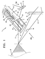
- the device 1 shown in Fig. 1 for entering a Weft thread 2 for a rapier weaving machine contains a donor rapier 3 and a deflection guide 4.
- the one to be fed Weft thread 2 extends from the edge of a fabric 8 through a thread guide eyelet 6 of a thread feeder 5 to a weft supply, not shown.
- the Weft 2 runs in the direction of B from the weft supply the thread feeder 5.
- the deflection guide 4 is in the illustrated embodiment Part of a guide profile 9, which is a gripper belt 17 leads, on which a holder 16 is attached which the encoder gripper 3 is mounted (Fig. 4). Furthermore 1 are warp threads 10, 11 of a warp thread family and Shed formation means 12, 13 indicated that a shed 14 form the warp threads 10, 11. For the sake of clarity a sley with a reed not shown, which itself is located between the fabric 8 and the shedding means 12, 13.
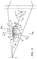
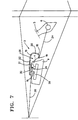
- FIG. 2 shows the position of the encoder gripper to the deflection guide 4.
- the weft thread 2 runs from the thread guide eyelet 6 over the deflection edge 7 of the deflection guide 4 to the Goods edge of the fabric 8 with which the previously fed Weft connected after striking with the help of the reed remains.
- Fig. 1 to 5 there is the encoder gripper 3 essentially from a curved plate 15, in particular from a stainless steel plate or aluminum plate, which means a holder 16 is connected to a gripper belt 17.
- the Plate 15 is bent into a U-shaped cross section so that it extends in the longitudinal direction of the master gripper 3 Hollow chamber 31 forms.
- This hollow chamber 31 is at the front and rear end of the gripper 3 and to the deflection guide 4 open as can be seen from the further description still results.
- Fig. 1 has the U-shaped Plate 15 a long leg that over the deflection guide 4 is arranged, and a short leg that is to the side of the deflection guide 4.
- the donor gripper with means for picking up the weft thread 2, with means for positioning of the weft thread 2 within the donor gripper 3 and with Means to take away or pinch the picked weft equipped.
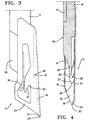
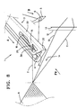
- the front end of the encoder gripper 3, the essentially only from the crossbar connecting the legs 32 is wedge-shaped to a point 20, as can be seen in particular from FIG. 4.
- the sloping one Bottom of the crosspiece 32 forms together with the at a distance to the beginning of 20 short legs one as Guide designed receptacle 18 for the weft.
- the weft 2 slides down on this receptacle 18 (FIG.
- a tab 25 is cut out and bent inwards, which forms a second means for receiving the weft thread 2.
- This tab 25 extends obliquely to the front and then forms an approximately wedge-shaped Tip 26 has a guide surface 21 which slants the weft up into the plane of the longer leg 24 to one recess 22 provided there leads as a second means is used for positioning.
- FIGS. 2 and 7 detects this serving as a means for receiving tab 25 the Section 2B of the weft thread, which is between the deflecting edge 7 and the edge of the fabric 8 is located.
- the of the Tip 26 of the tab 25 forms an edge 27 running downwards an oblique guide that is flush with a web 28 of the holder 16 connects, which is inclined to the foot part 29 of the holder 16 runs out, which is arranged in the extension of the gripper belt 17 is.
- the encoder gripper 3 contains a thread clamp 30, attached to the longer leg 24 of the plate 15 inside is.
- the thread clamp 30 is located at a point between the guide surface 21 of the tab 25 and the tissue 8 lies.
- the thread clamp 30 is in the embodiment from a leaf spring, which is in the direction of movement A of The gripper runs at the bottom of the plate 15 is attached inside.
- the thread clamp 30 acts on the inside the plate 15 together.
- the tab 25 as a means for picking up, guides the weft section 2B also the thread clamp 30.
- the encoder gripper 3 is such designed that its height starting from the top towards to the gripper belt 17 increases steadily so that there are none Places where warp threads 10, 11 can be detected.
- the tip 26 of the tab 25 projects into the Hollow chamber 31 into it, but only with a size that is less than half the height of the web is 32.
- the distance C according to FIG. 2 is between the inside of the longer leg 24 of the plate 15 and the deflection edge 7 of the deflection part 4 at least 2 mm, preferably between 3 and 5mm.
- the deflection edge protrudes 7 of the deflection guide 4 of the weft thread 2 in the the plate 15 formed hollow chamber 31 in such a way that the Means for picking up the weft thread 2, i.e. that of the Tip 20 of the web 32 outgoing guide 18 and the Tip 26 of the tab 25 outgoing guide 21 each on opposite Sides of the deflection edge 7 are. Since the Hollow chamber 31 is open at the front and back, the encoder gripper can 3 move freely along the deflection guide 4.
- the ready weft thread obliquely from the fabric edge of the fabric 8 to the thread feeder 5 via the deflection edge 7, i.e. obliquely to the direction of movement A of the encoder gripper 3 of the Tissue 8 away.
- the deflection edge 7 which in Direction of movement A must be correspondingly long.
- the weft 2 successively taken up by the guide surfaces 18 and 21 and also one after the other in the recesses 19 and 22 positioned and also inserted into the weft clamp 30 is a gradual increase in the voltage in the Weft so that the risk of weft breakage is reduced is.
- An increase in the tension of the weft thread 2 takes place if the weft 2 due to guiding along the Guide surfaces 18 and 21 and / or extended on the deflection edge becomes.
- FIGS. 1 to 11 Deviating from the embodiment of FIGS. 1 to 11 must of course the weft thread 2 is not between a thread feeder 5 and the tissue 8 are kept ready.
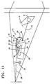
- FIG 12 shows an exemplary embodiment, in which a weft thread 2 by means of a thread guide 33 is provided, which is described in a US 4,840,203 disclosed manner on a weaving loom of a weaving machine is appropriate.
- the weft thread is in the area of the fabric 8 2 fed by means of a feed clamp 34, which via a Mechanism according to US 4,840,203 is moved.
- weft thread 2 is also such a deflection edge 7 guided a deflection guide 4 that he is already in the described manner in the region of the hollow chamber 31 of the Giver gripper 3 is located, so that it gradually increases Voltage can be picked up by the encoder gripper 3 when it moves in direction A towards the shed.
- the weft thread by means of the thread clamp 30 is not directly clamped to the underside of the plate 15. Rather is a Intermediate piece 36 made of metal provided by means of a or more elastic elements 37 attached to the plate 15 is.
- the elastic elements 37 are, for example made of a rubber-like elastic liner and insulating material.
- the deflection guide 4 with the deflection edge 7 not in one piece the guide profile 9, but rather as its own Component manufactured and by means of screws 42 or the like. to the Guide profile 9 is attached.
- a U-shaped plate 15 is provided, which one located above the deflection edge 7 of the deflection guide 4 long legs and one on the side next to the deflection guide has short legs located and a hollow chamber 31 forms, in which the deflection edge 7 of the deflection guide 4th protrudes such that the weft thread 2 on both sides of the deflection guide 4 is added.
- the web 32 of the U-shaped plate is shorter than the upper one Leg, so that the guide surface serving as a means for receiving 39 essentially at the upper edge of the web begins and then to one that serves as a means of positioning Recess 19 of the short leg runs.
- the upper Leg forms a tip 40 that faces inwards to the hollow chamber something is bent towards the detection of warp threads to avoid.
- One of the longer legs is on the inside Tab 25 bent, which forms a tip 26, one of which serving as a means for receiving the weft thread guide surface 21 leads to a recess 22 which as a means for Positioning the weft serves.
- the clamp also exists with this Embodiment from a leaf spring strip, which on the Attached inside the longer leg of the plate 15 is.
- the slopes 53 form a point directed to the stop line 51.
- the plane 50 runs in which the Guide surfaces 48 of the guide elements 43 lie somewhat below the stop edge 51, i.e. the edge of a fabric, against which the Webblatt 47 a registered Weft thread.
- the encoder gripper 3 of the embodiment 1 to 13 or the encoder gripper 3 'of FIGS. 14 to 16 is provided with a sliding surface 46 with which it is outside is guided on an outer surface 45 of the guide elements 43.
- the sliding surface 46 is a section of the short leg of the U-shaped plate that extends towards the shed towards the one used for positioning Recess 19 connects, for example in FIG. 5 and 16 can be seen.
- the approach 44 of the guide elements 43 protrudes into the hollow chamber 31 of the master gripper 3.
- the forms the sliding surface 46 with a slide bar or Coating is provided, which consists of a well lubricated, wear-resistant material.
- the Approaches 44 of the guide elements 43 none of the top of the Gripper belt 17 and the foot part 29 of the holder 16 assigned Guide surface 52.
Description
Die Erfindung betrifft einen Gebergreifer für eine Greiferwebmaschine, der mit Mitteln zum Aufnehmen und Positionieren eines Schußfadens versehen ist, der auf einer Umlenkführung aufliegend bereitgehalten ist.The invention relates to a sensor rapier for a rapier weaving machine, with means for picking up and positioning a weft thread is provided on a deflecting guide is kept on hand.
Bei Greiferwebmaschinen wird üblicherweise ein Schußfaden mit Hilfe eines Gebergreifers und eines Nehmergreifers durch das Webfach hindurchgeführt. Der Gebergreifer nimmt an der Eintragsseite des Webfaches einen Schußfaden auf, der mittels eines Fadenzubringers bereitgehalten wird. Wenn der Gebergreifer in das Webfach eingeführt wird, wird der Schußfaden aufgenommen, innerhalb des Gebergreifers positioniert und mittels einer Klemme geklemmt. In etwa in der Mitte des Webfaches wird der Schußfaden von einem Nehmergreifer übernommen, von einer Klemme des Nehmergreifers geklemmt und von dem Nehmergreifer zur anderen Seite des Webfaches gebracht. Der Gebergreifer bewegt sich während dieser Zeit leer zurück in seine Ausgangsstellung vor der Eintragsseite des Webfaches.In rapier weaving machines, a weft thread is usually used Help from a donor gripper and a slave gripper Loom passed through. The encoder gripper takes on the entry side of the shed on a weft, which means a thread feeder is kept ready. If the encoder gripper is inserted into the shed, the weft picked up, positioned within the encoder gripper and clamped by means of a clamp. Approximately in the middle of the shed the weft thread is taken over by a slave gripper, clamped by a clamp of the slave gripper and by that Take gripper to the other side of the shed. The The encoder gripper moves back in empty during this time its starting position in front of the entry page of the shed.
Es ist auch bekannt, bei Greiferwebmaschinen einen Schußfaden nur mit Hilfe eines Gebergreifers durch das Webfach hindurch zu transportieren. Der Gebergreifer, der den Schußfaden an der Eintragsseite des Webfaches aufnimmt, bewegt sich dann zu der gegenüberliegenden Seite des Webfaches, wo der Schußfaden von dem Gebergreifer freigegeben und von einem Nehmerhaken o.dgl. übernommen wird.It is also known to use a weft thread in rapier weaving machines only with the help of a donor gripper through the shed to transport. The donor gripper, which is the weft the entry page of the shed then moves to the opposite side of the shed where the weft released by the encoder gripper and by a slave hook or the like is taken over.
Es ist bekannt (US 4.653.544), daß der Fadenzubringer den Schußfaden auf eine Umlenkführung auflegt, so daß dieser Schußfaden in einer definierten Position bereitgehalten ist, in welcher er sicher von dem Gebergreifer aufgenommen werden kann, wenn dieser sich zum Webfach hin bewegt.It is known (US 4,653,544) that the thread feeder Weft thread on a deflection guide, so that this Weft is kept in a defined position, in which it can be safely picked up by the encoder gripper can if it moves towards the shed.
Es ist bekannt (EP 0 509 255 A1), einen Gebergreifer ausgehend von seiner Spitze mit einer Führungsfläche zu versehen, die zu einem querverlaufenden Schlitz führt, in welchen der aufzunehmende Schußfaden hineinfällt. Nachdem der Schußfaden in diesen Schlitz hineingefallen ist, kann er nicht mehr aus dem Gebergreifer herausrutschen. Es können jedoch nur Schußfäden verwoben werden, die leicht durch den Schlitz hindurch gehen, so daß dicke Schußfäden oder Schußfäden mit Verdickungen nur schwer oder gar nicht verwoben werden können. Ein weiterer Nachteil besteht darin, daß der aufzunehmende Schußfaden beim Hineinfallen in den Schlitz seine Spannung verliert und danach völlig schlaff liegt. Wenn der Schußfaden, der innerhalb des Gebergreifers positioniert wird, anschließend durch die Bewegung des Gebergreifers gespannt wird, wird er ruckartig belastet. Dies führt zu einer Erhöhung der Gefahr von Schußfadenbrüchen.It is known (EP 0 509 255 A1) starting from a sensor gripper to provide a guide surface from its tip, which leads to a transverse slot in which the weft thread to be picked up. After the weft has fallen into this slot, it can no longer fall out slip out of the encoder gripper. However, only weft threads can be used that are easily woven through the slit go so that thick weft threads or weft threads with thickening can only be woven with difficulty or not at all. On Another disadvantage is that the weft thread to be picked up when it falls into the slot it loses its tension and then lies completely limp. If the weft, which is positioned within the encoder gripper, then is stretched by the movement of the gripper he jerkily charged. This leads to an increased risk of weft breaks.
Es ist auch bekannt (EP 0 441 099 A1), als Gebergreifer eine im wesentlichen U-förmige Platte vorzusehen. Der Quersteg dieser U-förmigen Platte ist als eine Gleitfläche für die Kettfäden eines Unterfaches ausgebildet. Der dem Warenrand des Gewebes zugewandte Schenkel bildet eine Führungsfläche für den aufzunehmenden Schußfaden, mittels der der Schußfaden direkt zu einer Klemme geführt wird, in die der Schußfaden einläuft. An dem anderen Schenkel ist ebenfalls eine Führungsfläche und eine als Positioniermittel dienende Aussparung vorgesehen. Bei dieser Bauart besteht die Gefahr, daß die Führungsfläche des dem Warenrand zugewandten Stegs einen nicht ganz korrekt verlaufenden Kettfaden erfaßt und der Klemme des Greifers zuführt. Dies führt dann unvermeidlich zu einem Kettfadenbruch.It is also known (EP 0 441 099 A1) as a pick-up gripper to provide a substantially U-shaped plate. The crossbar This U-shaped plate is used as a sliding surface for the Warp threads of a lower compartment formed. The edge of the goods the leg facing the fabric forms a guide surface for the weft to be picked up, by means of which the weft is led directly to a clamp in which the weft thread comes in. There is also a guide surface on the other leg and a recess serving as a positioning means intended. With this design there is a risk that the guide surface of the web facing the edge of the goods not correctly running warp thread and the Clamp of the gripper feeds. This then inevitably leads to a warp thread break.
Der Erfindung liegt die Aufgabe zugrunde, einen Gebergreifer der eingangs genannten Art so auszubilden, daß ein bereitgelegter Schußfaden sicher ergriffen wird, jedoch die Gefahr des Ergreifens eines Kettfadens wesentlich verringert ist.The invention has for its object a donor gripper of the type mentioned in such a way that a ready Weft is taken safely, however, the danger gripping a warp thread is significantly reduced.
Diese Aufgabe wird dadurch gelöst, daß der Gebergreifer eine sich in Längsrichtung erstreckende, vorne und hinten sowie auf der der Umlenkführung zugewandten Seite offene, die Umlenkführung umgreifende Hohlkammer bildet.This object is achieved in that the encoder gripper extending longitudinally, front and back as well on the side facing the deflection guide, the deflection guide encompassing hollow chamber.
Der erfindungsgemäße Gebergreifer kann einen bereitgehaltenen Schußfaden gut ergreifen, der aufgrund der Umlenkführung einen von einer möglichen Laufrichtung eines Kettfadens deutlich verschiedenen Verlauf hat, sicher aufnehmen. Andererseits ist der Gefahr relativ gering, daß der Gebergreifer einen nicht korrekt verlaufenden Kettfaden fängt. Darüber hinaus bestehen keine Beschränkungen bezüglich der Abmessungen eines aufzunehmenden Schußfadens.The encoder gripper according to the invention can have one ready Grip the weft well because of the deflection guide of a possible running direction of a warp thread clearly has different course, record safely. On the other hand the risk is relatively small that the encoder gripper catches incorrectly running warp thread. Furthermore there are no dimensional restrictions of a weft thread to be picked up.
In Ausgestaltung der Erfindung wird vorgesehen, daß die Mittel zum Aufnehmen eines Schußfadens in verschiedenen Wänden der Hohlkammer angeordnet sind. Damit wird erreicht, daß die Spannung des Schußfadens bei der Mitnahme durch den Gebergreifer stufenweise erhöht wird, so daß die Gefahr von Schußfadenbrüchen begrenzt wird.In an embodiment of the invention it is provided that the means for picking up a weft thread in different walls the hollow chamber are arranged. This ensures that the Tension of the weft thread when carried by the donor gripper is gradually increased so that the risk of weft breaks is limited.
In weiterer Ausgestaltung der Erfindung wird vorgesehen, daß die Mittel zum Positionieren in zwei verschiedenen Wänden der Hohlkammer angeordnet sind und einander mit Abstand gegenüberliegen. Damit wird erreicht, daß der Gebergreifer ein Stück des Schußfadens frei in seiner Hohlkammer hält, so daß es sehr gut von einem Nehmergreifer oder auch von einem Nehmerhaken übernommen werden kann.In a further embodiment of the invention it is provided that the means for positioning in two different walls of the Hollow chamber are arranged and face each other at a distance. This ensures that the encoder gripper a Holds piece of the weft freely in its hollow chamber, so that it very well from a slave gripper or even from a slave hook can be taken over.
In weiterer Ausgestaltung der Erfindung wird vorgesehen, daß die Mittel zum Aufnehmen und/oder die Mittel zum Positionieren in Bewegungsrichtung des Gebergreifers bezüglich der Position des bereitgehaltenen Schußfadens zueinander versetzt sind. Damit wird erreicht, daß die Spannung des Schußfadens bei der Mitnahme durch den Gebergreifer stufenweise erhöht wird, so daß die Gefahr von Schußfadenbrüchen weiter begrenzt ist.In a further embodiment of the invention it is provided that the means for receiving and / or the means for positioning in the direction of movement of the gripper with respect to the position the weft thread held ready to each other are. This ensures that the tension of the weft thread gradually increased when carried by the encoder gripper is, so that the risk of weft breakage is further limited is.
In Ausgestaltung der Erfindung wird vorgesehen, daß dem Mittel zum Positionieren, das dem Warenrand eines zu webenden Gewebes zugeordnet ist, als Mittel zum Aufnehmen eine nach innen in den Gebergreifer ragende Lasche zugeordnet ist, die eine zu dem Mittel zum Positionieren führende Führungsfläche bildet. Die dem Warenrand eines zu webenden Gewebes zugewandte Seite des Gebergreifers ist stärker gefährdet bezüglich einer ungewollten Aufnahme eines Kettfadens. Da das Mittel zum Aufnehmen, nämlich die Lasche in den Gebergreifer hineinragt, wird ein möglicher Kontakt dieser Lasche mit einem Kettfaden weitgehend ausgeschlossen.In an embodiment of the invention it is provided that the agent to position the the edge of the goods to be woven Tissue is assigned as a means of picking up one after is assigned to the inside protruding tab in the encoder gripper a guide surface leading to the positioning means forms. The facing the fabric edge of a fabric to be woven The gripper side is more vulnerable regarding an unwanted picking up of a warp thread. Because the means to pick up, namely the tab protrudes into the encoder gripper, there is a possible contact of this tab with a Warp thread largely excluded.
In weiterer Ausgestaltung der Erfindung wird vorgesehen, daß in dem Gebergreifer eine Fadenklemme untergebracht ist, die bezüglich der Mittel zum Positionieren auf der dem Warenrand zugewandten Seite angeordnet ist. Mit dieser Ausbildung wird erreicht, daß die Fadenklemme nur zum Klemmen des aufgenommenen Schußfadens dient, jedoch nicht zum Positionieren. Damit ist die Position des Schußfadens nur durch die Mittel zum Positionieren definiert, so daß er sich immer an der gleichen Stelle befindet und deshalb sicher von einem Nehmergreifer oder Nehmerhaken übernommen werden kann.In a further embodiment of the invention it is provided that a thread clamp is accommodated in the encoder gripper regarding the means for positioning on the edge of the goods facing side is arranged. With this training achieved that the thread clamp only for clamping the recorded Weft thread is used, but not for positioning. In order to is the position of the weft only by the positioning means defined so that he is always on the same Location and therefore safe from a slave gripper or slave hook can be taken over.
In weiterer Ausgestaltung der Erfindung wird vorgesehen, daß der Gebergreifer aus einer im wesentlichen U-förmigen Platte gebildet ist, die - in Bewegungsrichtung des Gebergreifers gesehen - einen über der Umlenkführung befindlichen Schenkel und einen seitlich neben der Umlenkführung befindlichen Schenkel besitzt. Dabei ist es vorteilhaft, wenn die Mittel zum Aufnehmen - gesehen in der Bewegungsrichtung des Gebergreifers - sich auf gegenüberliegenden Seiten der Umlenkführung befinden.In a further embodiment of the invention it is provided that the encoder gripper from a substantially U-shaped plate is formed, - in the direction of movement of the encoder gripper seen - a leg located above the deflection guide and one on the side next to the deflection guide Owns thigh. It is advantageous if the funds to pick up - seen in the direction of movement of the gripper - on opposite sides of the deflection guide are located.
In weiterer Ausgestaltung der Erfindung wird vorgesehen, daß der Gebergreifer mit einer Gleitfläche versehen ist, die Führungsmitteln zugeordnet ist, in denen ein Halter für den Gebergreifer und/oder für ein Greiferband geführt sind. Dadurch ist es möglich, den Gebergreifer innerhalb des Webfaches direkt zu führen und abzustützen.In a further embodiment of the invention it is provided that the encoder gripper is provided with a sliding surface, the guide means is assigned in which a holder for the encoder gripper and / or are guided for a gripper belt. Thereby it is possible to directly the encoder gripper within the shed to guide and support.
Weitere Merkmale und Vorteile der Erfindung ergeben sich aus der nachfolgenden Beschreibung der in den Zeichnungen dargestellten Ausführungsbeispielen.
- Fig. 1
- zeigt eine perspektivische Ansicht eines Ausschnittes einer Greiferwebmaschine mit einem erfindungsgemäßen Gebergreifer,
- Fig. 2
- eine Ansicht der Fig. 1 in Richtung des Pfeiles F2 der Fig. 1,
- Fig. 3
- eine Draufsicht des Ausschnittes der Fig. 1 und 2 in Richtung des Pfeiles F3 der Fig. 2,
- Fig. 4
- einen Schnitt entlang der Linie IV-IV der Fig. 2,
- Fig. 5
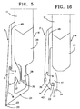
- eine Ansicht von unten des Ausschnittes der Fig. 2 in Richtung des Pfeiles F5,
- Fig. 6
- eine Ansicht ähnlich Fig. 1 in einer vorgeschobenen Position des Gebergreifers,
- Fig. 7
- eine Ansicht des Ausschnittes der Fig. 6 in Richtung des Pfeiles F7 der Fig. 6,
- Fig. 8
- eine perspektivische Ansicht ähnlich Fig. 1 und 6 in einer noch weiter vorgeschobenen Position des Gebergreifers,
- Fig. 9
- eine Ansicht in Richtung des Pfeiles F9 der Fig. 8,
- Fig. 10
- eine perspektivische Ansicht des Ausschnittes nach Fig. 1, 6 und 8 in einer noch weiter vorgeschobenen Position des Gebergreifers,
- Fig. 11
- eine Ansicht in Richtung des Pfeiles F11 der Fig. 10,
- Fig. 12
- eine Ansicht ähnlich Fig. 2 auf eine abgewandelte Ausführungsform,
- Fig. 13
- eine vergrößerte Darstellung des Ausschnittes F13 der Fig. 12,
- Fig. 14
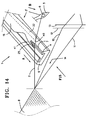
- eine perspektivische Ansicht ähnlich Fig. 1 einer weiteren abgewandelten Ausführungsform,
- Fig. 15
- eine Ansicht in Richtung des Pfeiles F15 der Fig. 14,
- Fig. 16
- eine Ansicht von unten in Richtung des Pfeiles F16 der Fig. 15,
- Fig. 17
- eine Ansicht ähnlich Fig. 2 einer abgewandelten Ausführungsform während sich der Gebergreifer bereits in einem Webfach befindet,
- Fig. 18
- eine Ansicht in Richtung des Pfeiles F18 der Fig. 17 und
- Fig. 19
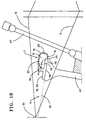
- eine Ansicht ähnlich Fig. 17 einer abgewandelten Ausführungsform.
- Fig. 1
- shows a perspective view of a section of a rapier weaving machine with a donor rapier according to the invention,
- Fig. 2
- 1 in the direction of arrow F2 of FIG. 1,
- Fig. 3
- 1 and 2 in the direction of arrow F3 of FIG. 2,
- Fig. 4
- 3 shows a section along the line IV-IV of FIG. 2,
- Fig. 5
- 2 shows a view from below of the detail of FIG. 2 in the direction of arrow F5,
- Fig. 6
- 1 in a forward position of the sensor gripper,
- Fig. 7
- 6 in the direction of arrow F7 of FIG. 6,
- Fig. 8
- 1 and 6 in a further advanced position of the pickup gripper,
- Fig. 9
- 8 shows a view in the direction of arrow F9 in FIG. 8,
- Fig. 10
- 1, 6 and 8 in a further advanced position of the transducer gripper,
- Fig. 11
- 10 shows a view in the direction of arrow F11 in FIG. 10,
- Fig. 12
- 3 shows a view similar to FIG. 2 of a modified embodiment,
- Fig. 13
- 12 shows an enlarged illustration of the detail F13 from FIG. 12,
- Fig. 14
- 2 shows a perspective view similar to FIG. 1 of a further modified embodiment,
- Fig. 15
- 14 shows a view in the direction of arrow F15 in FIG. 14,
- Fig. 16
- a view from below in the direction of arrow F16 of FIG. 15,
- Fig. 17
- 2 is a view similar to FIG. 2 of a modified embodiment while the donor gripper is already in a shed,
- Fig. 18
- a view in the direction of arrow F18 of FIGS. 17 and
- Fig. 19
- a view similar to FIG. 17 of a modified embodiment.
Die in Fig. 1 dargestellte Vorrichtung 1 zum Eintragen eines
Schußfadens 2 für eine Greiferwebmaschine enthält einen Gebergreifer
3 und eine Umlenkführung 4. Der zuzuführende
Schußfaden 2 erstreckt sich von dem Warenrand eines Gewebes 8
durch eine Fadenführungsöse 6 eines Fadenzubringers 5 hindurch
zu einem nicht dargestellten Schußfadenvorrat. Der
Schußfaden 2 läuft von dem Schußfadenvorrat in Richtung B zu
dem Fadenzubringer 5. Der Fadenzubringer 5, der beispielsweise
ein Bestandteil einer Fadenzuführeinrichtung entsprechend
dem US-Patent 5 400 834 ist, legt den Schußfaden 2 derart auf
die Umlenkführung 4 auf, daß er von dem Gebergreifer 3, der
sich in seiner Bewegungsrichtung A bewegt aufgenommen wird,
innerhalb des Gebergreifers positioniert und geklemmt wird
und anschließend mitgenommen wird.The
Die Umlenkführung 4 ist bei dem dargestellten Ausführungsbeispiel
Bestandteil eines Führungsprofils 9, das ein Greiferband
17 führt, an welchem ein Halter 16 angebracht ist, auf
dem der Gebergreifer 3 montiert ist (Fig. 4). Des weiteren
sind in Fig. 1 Kettfäden 10, 11 einer Kettfadenschar und
Fachbildungsmittel 12, 13 angedeutet, die ein Webfach 14 aus
den Kettfäden 10, 11 bilden. Aus Gründen der Deutlichkeit ist
eine Weblade mit einem Webblatt nicht dargestellt, die sich
zwischen dem Gewebe 8 und den Fachbildungsmitteln 12, 13 befindet.The
Die Ansicht nach Fig. 2 zeigt die Position des Gebergreifers
zur Umlenkführung 4. Der Schußfaden 2 läuft von der Fadenführungsöse
6 über die Umlenkkante 7 der Umlenkführung 4 zu dem
Warenrand des Gewebes 8, mit welchem der zuvor zugeführte
Schußfaden nach dem Anschlagen mit Hilfe des Webblattes verbunden
bleibt. The view of Fig. 2 shows the position of the encoder gripper
to the
Wie aus Fig. 1 bis 5 zu ersehen ist, besteht der Gebergreifer
3 im wesentlichen aus einer gebogenen Platte 15, insbesondere
aus einer Edelstahlplatte oder Aluminiumplatte, die mittels
eines Halters 16 mit einem Greiferband 17 verbunden ist. Die
Platte 15 ist zu einem U-förmigen Querschnitt gebogen, so daß
sie eine sich in Längsrichtung des Gebergreifers 3 erstrekkende
Hohlkammer 31 bildet. Diese Hohlkammer 31 ist am vorderen
und hinteren Ende des Gebergreifers 3 und zu der Umlenkführung
4 hin offen, wie sich aus der weiteren Beschreibung
noch ergibt. Wie aus Fig. 1 zu ersehen ist, besitzt die U-förmige
Platte 15 einen langen Schenkel, der über der Umlenkführung
4 angeordnet ist, und einen kurzen Schenkel, der
seitlich von der Umlenkführung 4 liegt. Wie im nachstehenden
noch erläutert werden wird, ist der Gebergreifer mit Mitteln
zum Aufnehmen des Schußfadens 2, mit Mitteln zum Positionieren
des Schußfadens 2 innerhalb des Gebergreifers 3 und mit
Mitteln zum Mitnehmen oder Klemmen des aufgenommenen Schußfadens
ausgerüstet. Das vordere Ende des Gebergreifers 3, das
im wesentlichen nur aus dem die Schenkel verbindenden Quersteg
32 besteht, ist keilförmig zu einer Spitze 20 angespitzt,
wie insbesondere aus Fig. 4 zu ersehen ist. Der längere
Schenkel 24 beginnt kurz nach der Spitze 20, wobei seine
Größe ausgehend von der Spitze zunimmt. Die schräg verlaufende
Unterseite des Querstegs 32 bildet zusammen mit dem in Abstand
zu der Spitze 20 beginnenden, kurzen Schenkel eine als
Führung gestaltete Aufnahme 18 für den Schußfaden. Der Schußfaden
2 gleitet auf dieser Aufnahme 18 nach unten (Fig. 2)
und erreicht dann eine als Mittel zum Positionieren dienende
Aussparung 19 des kurzen Schenkels. Wenn der Gebergreifer 3
in seiner Bewegungsrichtung A in Richtung zu dem Webfach 14
bewegt wird, so läuft zuerst die Aufnahme 18 gegen den Schußfaden
2 und führt diesen Schußfaden in die als Mittel zum Positionieren
dienende Aussparung 19. Wie aus Fig. 2 zu ersehen
ist, läuft die unterhalb der Spitze 20 beginnende, als Aufnahme
18 dienende Führungsfläche als erstes gegen den Abschnitt
2A des Schußfadens 2 an, der sich von der Umlenkkante
7 zu dem Fadenzubringer 5 erstreckt. Dieser Teil 2A des
Schußfadens wird somit als erstes kontaktiert und in die als
Mittel zum Positionieren dienende Aussparung 19 überführt.As can be seen from Fig. 1 to 5, there is the
Aus dem längeren Schenkel 24 der U-förmig gebogenen Platte
ist eine Lasche 25 ausgeschnitten und nach innen abgebogen,
die ein zweites Mittel zum Aufnehmen des Schußfadens 2 bildet.
Diese Lasche 25 erstreckt sich schräg nach vorne und
bildet anschließend an eine in etwa keilförmig gestaltete
Spitze 26 eine Führungsfläche 21, die den Schußfaden schräg
nach oben in die Ebene des längeren Schenkels 24 bis zu einer
dort vorgesehenen Aussparung 22 führt, die als zweites Mittel
zum Positionieren dient. Wie aus Fig. 2 und 7 zu ersehen ist,
erfaßt diese als Mittel zum Aufnehmen diendende Lasche 25 den
Abschnitt 2B des Schußfadens, der sich zwischen der Umlenkkante
7 und dem Warenrand des Gewebes 8 befindet. Die von der
Spitze 26 der Lasche 25 nach unten laufende Kante 27 bildet
eine schräge Führung, die bündig an einen Steg 28 des Halters
16 anschließt, der schräg zu dem Fußteil 29 des Halters 16
ausläuft, das in Verlängerung des Greiferbandes 17 angeordnet
ist.From the
Des weiteren enthält der Gebergreifer 3 eine Fadenklemme 30,
die innen an dem längeren Schenkel 24 der Platte 15 angebracht
ist. Die Fadenklemme 30 befindet sich an einer Stelle,
die zwischen der Führungsfläche 21 der Lasche 25 und dem Gewebe
8 liegt. Die Fadenklemme 30 besteht bei dem Ausführungsbeispiel
aus einer Blattfeder, die in Bewegungsrichtung A des
Gebergreifers verläuft und die an der Unterseite der Platte
15 innen angebracht ist. Die Fadenklemme 30 wirkt mit der Innenseite
der Platte 15 zusammen. Die Lasche 25, die als Mittel
zum Aufnehmen dient, führt den Schußfadenabschnitt 2B
auch der Fadenklemme 30 zu.Furthermore, the
Wie aus Fig. 4 zu ersehen ist, ist der Gebergreifer 3 derart
gestaltet, daß seine Höhe ausgehend von der Spitze in Richtung
zu dem Greiferband 17 stetig zunimmt, so daß es keine
Stellen gibt, an denen Kettfäden 10, 11 erfaßt werden können. As can be seen from Fig. 4, the
Ausgehend von der Spitze erstreckt sich neben der Aufnahme 18
eine Führungsfläche 23 zu dem oberen Schenkel 24 der Platte
15. Ebenso können keine Kettfäden 10, 11 zwischen der Fadenklemme
30 und der Platte 15 geklemmt werden. Die Spitze 26
der Lasche 25 befindet sich in Bewegungsrichtung A in einem
sicheren Abstand von der Spitze 20 des Gebergreifers 3, die
von dem Quersteg 32 der U-förmig gebogenen Platte 15 gebildet
ist. Der Quersteg 32 weist im Bereich der Spitze 26 der Lasche
25 eine derart große Höhe auf, daß die von dem Steg getrennten
Kettfäden von der Lasche 25 nicht erfaßt werden können.
Sofern sie überhaupt in diesen Bereich gelangen, werden
sie von den Führungskanten 27 und 28 in Richtung zu dem Fußteil
29 des Halters 16 abgelenkt. Wie insbesondere aus Fig. 4
zu ersehen ist, ragt die Spitze 26 der Lasche 25 zwar in die
Hohlkammer 31 hinein, jedoch nur mit einer Größe, die weniger
als die Hälfte der Höhe des Steges 32 beträgt.Starting from the tip extends next to the receptacle 18
a
Um das Verweben von Schußfäden 2 mit nahezu beliebiger Stärke
zu erleichtern, beträgt der Abstand C gemäß Fig. 2 zwischen
der Innenseite des längeren Schenkels 24 der Platte 15 und
der Umlenkkante 7 des Umlenkteils 4 wenigstens 2mm, vorzugsweise
zwischen 3 und 5mm.To interweave
Wie beispielsweise aus Fig. 2 zu ersehen ist, ragt die Umlenkkante
7 der Umlenkführung 4 des Schußfadens 2 in die von
der Platte 15 gebildete Hohlkammer 31 derart hinein, daß die
Mittel zum Aufnehmen des Schußfadens 2, d.h. die von der
Spitze 20 des Steges 32 ausgehende Führung 18 und die von der
Spitze 26 der Lasche 25 ausgehende Führung 21 jeweils auf gegenüberliegenden
Seiten der Umlenkkante 7 liegen. Da die
Hohlkammer 31 vorne und hinten offen ist, kann sich der Gebergreifer
3 unbehindert entlang der Umlenkführung 4 bewegen.As can be seen, for example, from FIG. 2, the deflection edge protrudes
7 of the
Wie aus Fig. 6 bis 11 zu ersehen ist, erfaßt zunächst die an
die Spitze 20 des Steges anschließende, als Aufnahme 18 dienende
Führungsfläche den Abschnitt 2A des bereitgehaltenen
Schußfadens 2, der sich von der Umlenkkante 7 bis zu der Führungsöse
6 des Fadenzubringers 5 erstreckt. Dieser wird nach
unten ausgelenkt, bis er in die als Mittel zum Positionieren
dienende Aussparung 19 des kurzen Steges gelangt. Danach erfaßt
die als Aufnahme dienende Lasche 25 oberhalb ihrer Spitze
26 mit der Führungsfläche 21 den Abschnitt 2B des Schußfadens
2, der sich von dem Warenrand des Gewebes 8 bis zur Umlenkkante
7 erstreckt.As can be seen from Fig. 6 to 11, first of all captures the
the
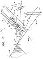
Wie aus Fig. 8 bis 11 zu ersehen ist, wird dabei bei dem weiter
Vorwärtsbewegen des Gebergreifers 3 in Richtung A der
Schußfaden 2 von der Umlenkkante 7 abgehoben, wobei er in die
als Mittel zum Positionieren dienende Aussparung 22 und auch
in die Fadenklemme 30 gelangt. Danach wird der Schußfaden mit
einer Schlagschere 35, die in Fig. 10 und 11 schematisch dargestellt
ist, in dem Bereich zwischen der Fadenklemme 30 und
dem Gewebe 8 abgeschnitten. Wie aus Fig. 11 zu ersehen ist,
liegt dann ein Abschnitt 2C des Schußfadens 2 frei innerhalb
der Hohlkammer 31 zwischen den das Positionieren bestimmenden
Aussparungen 19, 22, so daß dieser Schußfadenabschnitt 2C an
einer definierten Stelle liegt und sicher von einem Nehmergreifer
oder einem Nehmerhaken übernommen werden kann.As can be seen from FIGS. 8 to 11, this is further in the
Moving the
Wie beispielsweise aus Fig. 1 zu ersehen ist, verläuft der
bereitgehaltene Schußfaden schräg von dem Warenrand des Gewebes
8 zu dem Fadenzubringer 5 über die Umlenkkante 7, d.h.
schräg zu der Bewegungsrichtung A des Gebergreifers 3 von dem
Gewebe 8 hinweg. Bei dem Aufnehmen und Positionieren des
Schußfadens 2 innerhalb des Gebergreifers wird dieser in Bewegungsrichtung
A entlang der Umlenkkante 7 bewegt, die in
Bewegungsrichtung A entsprechend lang sein muß. Da der Schußfaden
2 nacheinander von den Führungsflächen 18 und 21 aufgenommen
und auch nacheinander in den Aussparungen 19 und 22
positioniert und auch in die Schußfadenklemme 30 eingebracht
wird, erfolgt eine stufenweise Erhöhung der Spannung in dem
Schußfaden, so daß die Gefahr von Schußfadenbrüchen verringert
ist. Eine Erhöhung der Spannung des Schußfadens 2 erfolgt,
wenn der Schußfaden 2 aufgrund des Führens entlang der
Führungsflächen 18 und 21 und/oder auf der Umlenkkante verlängert
wird.As can be seen from FIG. 1, for example, the
ready weft thread obliquely from the fabric edge of the
In der Praxis werden mehrere Fadenzubringer 5 vorgesehen, die
jeweils einen Schußfaden 2 des gleichen Typs oder auch verschiedener
Typen auf der Umlenkführung 4 zur Aufnahme und
Mitnahme durch den Gebergreifer 3 bereithalten können. An
sich wäre es günstig, wenn die Fadenzubringer den betreffenden
Schußfaden jeweils in der gleichen Position auf der Umlenkführung
4 ablegen. Aufgrund der Konstruktion des Gebergreifers
sind aber auch Abweichungen in der Richtung zulässig,
in welcher die verschiedenen Schußfäden 2 ausgehend von
dem Warenrand des Gewebes 8 zu dem Fadenzubringer 5 hin auf
der Umlenkkante 7 abgelegt werden. Es muß lediglich darauf
geachtet werden, daß der Fadenzubringer 5 in eine Höhenposition
gebracht wird, in welcher der Abschnitt 2A des Schußfadens
unterhalb der Spitze 20 des Steges 32 der U-förmig gebogenen
Platte 15 und der Abschnitt 2B des Schußfadens 2 oberhalb
der Spitze 26 der Lasche 25 liegen. Es erfolgt eine stufenweise
Erhöhung der Spannung in dem jeweiligen Schußfaden
2.In practice,
Abweichend von dem Ausführungsbeispiel nach Fig. 1 bis 11 muß
selbstverständlich der Schußfaden 2 nicht zwischen einem Fadenzubringer
5 und dem Gewebe 8 bereitgehalten werden. In
Fig. 12 ist beispielsweise ein Ausführungsbeispiel dargestellt,
bei welcher ein Schußfaden 2 mittels eines Fadenführers
33 bereitgehalten wird, der in einer der Beschreibung US
4 840 203 offenbarten Weise an einer Weblade einer Webmaschine
angebracht ist. Im Bereich des Gewebes 8 wird der Schußfaden
2 mittels einer Zuführklemme 34 zugeführt, die über einen
Mechanismus entsprechend der US 4 840 203 bewegt wird. Der
Schußfaden 2 wird jedoch ebenfalls derart über eine Umlenkkante
7 einer Umlenkführung 4 geführt, daß er sich in der bereits
beschriebenen Weise im Bereich der Hohlkammer 31 des
Gebergreifers 3 befindet, so daß er unter stufenweise zunehmender
Spannung vom Gebergreifer 3 aufgenommen werden kann,
wenn dieser sich in Richtung A zu dem Webfach hin bewegt.Deviating from the embodiment of FIGS. 1 to 11 must
of course the
Bei dem Ausführungsbeispiel nach Fig. 12 und 13 wird darüber
hinaus der Schußfaden mittels der Fadenklemme 30 nicht direkt
an der Unterseite der Platte 15 geklemmt. Vielmehr ist ein
Zwischenstück 36 aus Metall vorgesehen, das mittels eines
oder mehrerer elastischer Elemente 37 an der Platte 15 befestigt
ist. Die elastischen Elemente 37 bestehen beispielsweise
aus einer gummiartigen elastischen Zwischenlage und Dämmaterial.
Bei dieser Ausführungsform ist ferner vorgesehen, daß
die Umlenkführung 4 mit der Umlenkkante 7 nicht einteilig mit
dem Führungsprofil 9 ist, sondern vielmehr als ein eigenes
Bauteil hergestellt und mittels Schrauben 42 o.dgl. an dem
Führungsprofil 9 befestigt ist.In the exemplary embodiment according to FIGS. 12 and 13, this is above
furthermore, the weft thread by means of the
Das Ausführungsbeispiel des Gebergreifers 3' nach Fig. 14 bis
16 arbeitet zwar nach dem gleichen Prinzip wie der anhand von
Fig. 1 bis 13 erläuterte Gebergreifer 3, jedoch weicht er von
diesem konstruktiv ab. Auch bei diesem Ausführungsbeispiel
ist eine U-förmig gebogene Platte 15 vorgesehen, die einen
oberhalb der Umlenkkante 7 der Umlenkführung 4 befindlichen
langen Schenkel und einen seitlich neben der Umlenkführung
befindlichen kurzen Schenkel aufweist und die eine Hohlkammer
31 bildet, in welche die Umlenkkante 7 der Umlenkführung 4
derart hineinragt, daß der Schußfaden 2 beidseits der Umlenkführung
4 aufgenommen wird. Bei diesem Ausführungsbeispiel
ist der Steg 32 der U-förmigen Platte kürzer als der obere
Schenkel, so daß die als Mittel zum Aufnehmen dienende Führungsfläche
39 im wesentlichen an der Oberkante des Steges
beginnt und dann zu einer als Mittel zum Positionieren dienenden
Aussparung 19 der kurzen Schenkels läuft. Der obere
Schenkel bildet eine Spitze 40, die nach innen zu der Hohlkammer
hin etwas abgebogen ist, um das Erfassen von Kettfäden
zu vermeiden. Von dem längeren Schenkel ist nach innen eine
Lasche 25 abgebogen, die eine Spitze 26 bildet, von der eine
als Mittel zum Aufnehmen des Schußfadens dienende Führungsfläche
21 zu einer Aussparung 22 führt, die als Mittel zum
Positionieren des Schußfadens dient. Ferner ist bei der Ausführungsform
nach Fig. 14 bis 16 vorgesehen, daß die Fadenklemme
den Schußfaden im Bereich der zum Positionieren dienenden
Aussparung 22 gegen die Unterseite des längeren Schenkels
der Platte 15 klemmt. Die Klemme besteht auch bei diesem
Ausführungsbeispiel aus einem Blattfederstreifen, der an der
Innenseite des längeren Schenkels der Platte 15 befestigt
ist.The embodiment of the
Es ist bekannt (US 5 413 151), das den Gebergreifer 3 antreibende
Greiferband 17 und ggf. zusätzlich auch den den Gebergreifer
3 mit dem Greiferband 17 verbindenden Halter 16 innerhalb
des Webfaches 14 mittels einzelner Führungselemente
zu führen. Derartige Führungselemente 43 sind in Fig. 17 und
18 als Beispiel dargestellt. Diese Führungselemente, die an
einer Weblade angebracht sind, die auch das Webblatt 47
trägt, sind in regelmäßigen Abständen verteilt über die Webbreite
angeordnet und können durch die Kettfadenschar 11 des
Unterfaches hindurch in das Webfach 14 hineinbewegt werden.
Bei dem Ausführungsbeispiel weisen die Führungselemente 43
eine der Unterseite des Fußteils 29 des Halters 16 und der
Unterseite des Greiferbandes 17 zugeordnete Führungsfläche 48
auf, die sich über die gesamte Unterseite erstreckt. Ferner
besitzen sie einen hakenartigen Ansatz 44, der eine Führungsfläche
49 für die dem Webblatt 47 zugewandte Seitenkante des
Fußteils 29 des Halters 16 und/oder das Greiferband 17 sowie
eine Führungsfläche 52 für den an die betreffende Seitenfläche
anschließende Oberseite des Fußteils 29 und/oder des
Greiferbandes 17 bilden. Wie insbesondere aus Fig. 17 und 18
zu ersehen ist, sind die Führungselemente im Bereich der
schneidenartigen Führungsfläche 48 mit Schrägen 53 und im Bereich
des hakenförmigen Ansatzes 44 mit schrägen Flächen 54
angespitzt, um das Eindringen in das Webfach 14 durch die
Kettfadenschar 11 hindurch zu erleichtern. Die Schrägen 53
bilden eine zur Anschlaglinie 51 gerichtete Spitze. Wie aus
Fig. 17 zu ersehen ist, verläuft die Ebene 50, in welcher die
Führungsflächen 48 der Führungselemente 43 liegen, etwas unterhalb
der Anschlagkante 51, d.h. des Warenrandes eines Gewebes,
gegen welchen das Webblatt 47 einen eingetragenen
Schußfaden anschlägt.It is known (US Pat. No. 5,413,151) that drives the
Bei dem Ausführungsbeispiel nach Fig. 17 und 18 ist vorgesehen,
daß der Gebergreifer 3 des Ausführungsbeispiels nach
Fig. 1 bis 13 oder der Gebergreifer 3' nach Fig. 14 bis 16
mit einer Gleitfläche 46 versehen ist, mit welcher er außen
an einer Außenfläche 45 der Führungselemente 43 geführt ist.
Bei dem Ausführungsbeispiel ist die Gleitfläche 46 ein Abschnitt
des kurzen Schenkels der U-förmigen Platte, der sich
in Richtung zum Webfach hin nach der zum Positionieren dienenden
Aussparung 19 anschließt, der beispielsweise in Fig. 5
und 16 zu sehen ist. Wie insbesondere aus Fig. 17 zu ersehen
ist, liegt diese Gleitfläche 46 der Seitenkante des Greiferbandes
17 und/oder des Fußteils 29 des Halters 16 gegenüber,
so daß im Bereich des Gebergreifers 3 das Greiferband weitgehend
formschlüssig geführt ist. Der Ansatz 44 der Führungselemente
43 ragt in die Hohlkammer 31 des Gebergreifers 3.17 and 18 it is provided that
that the
Um einen möglichen Verschleiß zwischen der Gleitfläche 46 des
Gebergreifers 3 und der Außenfläche 45 der Führungselemente
gering zu halten, wird bei einer abgewandelten Ausführungsform
vorgesehen, daß der kurze Schenkel der Platte 15, der
die Gleitfläche 46 bildet, mit einer Gleitleiste oder einer
Beschichtung versehen ist, die aus einem gut gleitfähigen,
verschleißfesten Material besteht.To prevent possible wear between the sliding
Bei der abgewandelten Ausführungsform nach Fig. 19 weisen die
Ansätze 44 der Führungselemente 43 keine der Oberseite des
Greiferbandes 17 und des Fußteils 29 des Halters 16 zugeordnete
Führungsfläche 52 auf.In the modified embodiment according to FIG. 19, the
Die Erfindung ist nicht auf die dargestellten und erläuterten Ausführungsbeispiele beschränkt. Abwandlungen und insbesondere Kombinationen der einzelnen Ausführungsbeispiele untereinander sind ohne weiteres möglich. Der Schutzumfang wird ausschließlich durch die Patentansprüche bestimmt.The invention is not based on the illustrated and explained Embodiments limited. Variations and in particular Combinations of the individual exemplary embodiments with one another are easily possible. The scope of protection is exclusive determined by the claims.
Claims (15)
- Carrying gripper means (3, 3') for a gripper weaving machine, which is provided with means for taking up and positioning a weft thread (2) which is held ready on a guiding means (4, 7),
characterized in that the carrying gripper means (3, 3') forms a longitudinally extending cavity (31), which is open at the front and the rear and on the side facing the guiding means (4, 7), and which surrounds the said guiding means (4, 7). - Carrying gripper means in accordance with claim 1, characterized in that the means (18, 21, 39) for picking up a weft thread (2) are disposed on two different walls (24, 32) of the cavity (31).
- Carrying gripper means in accordance with claim 1 or claim 2, characterized in that the positioning means (19, 22) are disposed in two different walls (24, 32) of the cavity (31) and lie opposite each other with a gap between them.
- Carrying gripper means in accordance with any one of claims 1 to 3, characterized in that the uptake means (18, 21; 39) and/or the positioning means (19, 22) are displaced in relation to each other, in the direction of movement of the carrying gripper means, with relation to the position of the weft thread (2) held ready.
- Carrying gripper means in accordance with any one of claims 1 to 4, characterized in that the positioning means (22), which face the edge of a fabric (8) to be woven, is disposed as a means for taking up a tongue (25), which forms a guide surface (21) leading to the positioning means (22), which projects inwards into the carrying gripper means.
- Carrying gripper means in accordance with any one of claims 1 to 5, characterized in that a thread clip (30, 41), which, in relation to the positioning means (22), is disposed on the side facing the edge of the fabric, is accommodated in the carrying gripper means (3, 3').
- Carrying gripper means in accordance with any one of claims 1 to 6, characterized in that it is formed of a plate (15) which is essentially U-shaped, which, as seen in the direction of movement of the carrying gripper means (3), has a wing element (24), located above the guiding means (4, 7), and a wing-element located laterally next to the guiding means.
- Carrying gripper means in accordance with claim 7, characterized in that the uptake means (18, 21; 39), as seen in the direction of movement of the carrying gripper means, are located on opposite sides of the guiding means (4, 7).
- Carrying gripper means in accordance with claim 7 or 8, characterized in that a positioning means (22) and a thread clip (30, 41) are positioned on the upper wing-element (24), and in that a further positioning means (19) is disposed on the lateral wing-element.
- Carrying gripper means in accordance with any one of claims 7 to 9, characterized in that a tongue (25), as an uptake means, which projects inwards into the carrying gripper means (3), is arched out of the upper wing-element (24) and forms a guide surface (21) leading to a recess (22) serving as a positioning means.
- Carrying gripper means in accordance with any one of claims 7 to 10, characterized in that the plate (15) is conically tipped in the area of the front end, such that a tip (20) is present which is essentially only formed from the crosspiece (32).
- Carrying gripper means in accordance with claim 11, characterized in that the crosspiece (32), starting from the tip (20), serves as an uptake means and forms a guide surface (18) which leads to a recess (19) of the lateral wing-element serving as a positioning means.
- Carrying gripper means in accordance with any one of claims 1 to 12, characterized in that the carrying gripper means (3) is provided with a sliding surface (46) which has guide elements (43), associated with it, in which a holding means (16) for the carrying gripper means (3) and/or a rapier (17) is conveyed within a loom shed (14).
- Carrying gripper means in accordance with claim 13, characterized in that the sliding surface (46) is provided, in terms of the direction of movement into the loom shed (14), on the lateral wing-element of the plate (15), after the recess (19) serving for positioning.
- Carrying gripper means in accordance with any one of claims 1 to 14, characterized in that the guiding means (4, 7) is disposed on a stationary guide element (9) in which the rapier (17) and/or the holding means (16) of the carrying gripper means (3) are guided.
Applications Claiming Priority (5)
| Application Number | Priority Date | Filing Date | Title |
|---|---|---|---|
| BE9600520 | 1996-06-07 | ||
| BE9600520A BE1010334A3 (en) | 1996-06-07 | 1996-06-07 | Device for insertion of a weft thread in a gripper loom |
| BE9700210 | 1997-03-11 | ||
| BE9700210A BE1011038A6 (en) | 1997-03-11 | 1997-03-11 | Apparatus for inserting a weft thread in a gripper loom and a feeder gripper |
| PCT/EP1997/002973 WO1997047792A1 (en) | 1996-06-07 | 1997-06-07 | Transfer gripper for a rapier loom |
Publications (2)
| Publication Number | Publication Date |
|---|---|
| EP0906461A1 EP0906461A1 (en) | 1999-04-07 |
| EP0906461B1 true EP0906461B1 (en) | 2001-11-28 |
Family
ID=25663044
Family Applications (1)
| Application Number | Title | Priority Date | Filing Date |
|---|---|---|---|
| EP97928158A Expired - Lifetime EP0906461B1 (en) | 1996-06-07 | 1997-06-07 | Transfer gripper for a rapier loom |
Country Status (4)
| Country | Link |
|---|---|
| US (1) | US6179014B1 (en) |
| EP (1) | EP0906461B1 (en) |
| DE (1) | DE59705563D1 (en) |
| WO (1) | WO1997047792A1 (en) |
Cited By (2)
| Publication number | Priority date | Publication date | Assignee | Title |
|---|---|---|---|---|
| WO2005047584A1 (en) * | 2003-10-21 | 2005-05-26 | Picanol N.V. | Method for selecting and feeding weft yarns, and a rapier weaving machine equipped with a device for selecting and feeding weft yarns |
| WO2008104355A1 (en) * | 2007-02-26 | 2008-09-04 | Picanol N.V. | A gripper weaving machine provided with a bringer gripper and a deflecting guide |
Families Citing this family (7)
| Publication number | Priority date | Publication date | Assignee | Title |
|---|---|---|---|---|
| IT1303764B1 (en) * | 1998-11-17 | 2001-02-23 | S M I T S R L Societa Macchine | CLAMP OF PIPES FOR FRAMES WITHOUT SHUTTLE PARTICULARLY SUITABLE FOR THE CONTEMPORARY INTRODUCTION OF MORE PLOTS INTO THE ORDER MOUTH |
| ATE447059T1 (en) * | 2002-09-20 | 2009-11-15 | Picanol Nv | ENCODER GRIPPER FOR A CLIPPER WEAVING MACHINE |
| DE10349644A1 (en) * | 2003-10-21 | 2005-06-02 | Picanol N.V. | Device for selecting and delivering weft threads to a gripper of a rapier weaving machine |
| ES2318443T3 (en) * | 2005-05-17 | 2009-05-01 | Promatech S.P.A. | GRIP SUPPORT FOR WEAVING WITH DEVICE (ANTI-LOOP) TO PREVENT ANTICIPATED GRIP GRIP. |
| EP1918437A1 (en) * | 2006-11-02 | 2008-05-07 | Sultex AG | Method and device for weft insertion |
| EP2037023A1 (en) * | 2007-09-12 | 2009-03-18 | Sultex AG | Thread clamp for a gripper head and method for operating the same |
| BE1026412B1 (en) * | 2018-06-21 | 2020-01-30 | Nv Michel Van De Wiele | VEGETABLE HEAD |
Family Cites Families (9)
| Publication number | Priority date | Publication date | Assignee | Title |
|---|---|---|---|---|
| JPS5922128Y2 (en) * | 1979-07-10 | 1984-07-02 | 株式会社豊田自動織機製作所 | Weft insertion device for shuttleless looms |
| DE3565132D1 (en) * | 1984-04-06 | 1988-10-27 | Picanol Nv | Weft cancellation mechanism for gripper looms |
| NL8600857A (en) * | 1986-04-03 | 1987-11-02 | Picanol Nv | Method for clamping, holding and presenting weft threads at rapier weaving machines and apparatus used for this purpose. |
| IT1238606B (en) * | 1990-01-26 | 1993-08-18 | Nuovo Pignone Spa | PERFECTED WEFT STITCHING DEVICE IN A TEXTILE FRAME WITHOUT SHUTTLE |
| EP0441099B1 (en) * | 1990-02-05 | 1996-01-31 | Sulzer RàTi Ag | Weft carrying gripper for gripper looms |
| IT1245579B (en) * | 1991-03-22 | 1994-09-29 | Somet Soc Mec Tessile | CARRIER GRIPPER FOR WEAVING FRAMES WITHOUT SHUTTLE |
| BE1006347A3 (en) * | 1992-11-16 | 1994-07-26 | Picanol Nv | DEVICE FOR PRESENTING weft threads in weaving machines. |
| IT1290838B1 (en) * | 1996-02-27 | 1998-12-14 | Nuovo Pignone Spa | PERFECTED CONDUCT CLAMP FOR CLAMP TEXTILE FRAME |
| EP0812938B1 (en) * | 1996-06-14 | 2001-04-04 | Sulzer Textil AG | Support for a thread clamp and feeding gripper for gripper loom with such support |
-
1997
- 1997-06-07 WO PCT/EP1997/002973 patent/WO1997047792A1/en active IP Right Grant
- 1997-06-07 DE DE59705563T patent/DE59705563D1/en not_active Expired - Lifetime
- 1997-06-07 US US09/147,347 patent/US6179014B1/en not_active Expired - Lifetime
- 1997-06-07 EP EP97928158A patent/EP0906461B1/en not_active Expired - Lifetime
Cited By (3)
| Publication number | Priority date | Publication date | Assignee | Title |
|---|---|---|---|---|
| WO2005047584A1 (en) * | 2003-10-21 | 2005-05-26 | Picanol N.V. | Method for selecting and feeding weft yarns, and a rapier weaving machine equipped with a device for selecting and feeding weft yarns |
| WO2008104355A1 (en) * | 2007-02-26 | 2008-09-04 | Picanol N.V. | A gripper weaving machine provided with a bringer gripper and a deflecting guide |
| BE1017477A3 (en) * | 2007-02-26 | 2008-10-07 | Picanol Nv | A GRIJPER WEAVING MACHINE WITH A GRAINER AND A BENDING GUIDE. |
Also Published As
| Publication number | Publication date |
|---|---|
| US6179014B1 (en) | 2001-01-30 |
| EP0906461A1 (en) | 1999-04-07 |
| WO1997047792A1 (en) | 1997-12-18 |
| DE59705563D1 (en) | 2002-01-10 |
Similar Documents
| Publication | Publication Date | Title |
|---|---|---|
| DE3136615C2 (en) | Feeding and removing grippers for the weft thread of a shuttleless loom | |
| DE2845299C2 (en) | Shuttleless rapier weaving machine | |
| CH661297A5 (en) | PROTECTIVE WEAVING MACHINE WITH MEANS FOR THE REMOVAL OF DEFECTIVE AND / OR ERRORALLY ENROLLED Weft Threads FROM THE WEB COMPARTMENT. | |
| EP0906461B1 (en) | Transfer gripper for a rapier loom | |
| DE1785385B2 (en) | FEEDER GRIPPER FOR WEAVING MACHINES WITH CONTINUOUS WEFT FEED | |
| EP0441099B1 (en) | Weft carrying gripper for gripper looms | |
| EP0468916B1 (en) | Gripper loom with guiding blades for the grippers | |
| DE2643627C2 (en) | Bringer gripper for weaving machines with removal of the weft thread from stationary bobbins | |
| EP0620303A1 (en) | Gripper loom | |
| DE2907540C2 (en) | Gripper for weaving machines with removal of the weft thread from stationary bobbins | |
| DE3926637A1 (en) | Weft thread gripper bar for a contactless weaving chair | |
| CH660043A5 (en) | DEVICE ON A CONTINUOUS WEAVING MACHINE FOR MAKING A FABRIC EDGE. | |
| DE3003105C2 (en) | ||
| DE2642809A1 (en) | TICKET GRIPPER FOR WEAVING MACHINES WITH REMOVAL OF THE WEFT FROM FIXED SPOOLS | |
| EP0624671B1 (en) | Thread retainer for a supply gripper and gripper loom with thread retainer | |
| DE3421638C2 (en) | Reed with integrated insertion channel for a shuttleless weaving machine with pneumatic weft insertion | |
| DE2622397A1 (en) | WEFT TAKER CARRIER FOR WEAVING MACHINES | |
| EP0457718B1 (en) | Gripper clamp for looms | |
| DE60220788T2 (en) | Improvements to weft grippers for weaving machines and looms with guiding means therefor | |
| EP0811712B1 (en) | Thread clamp for a feeding gripper and feeding gripper with such a clamp | |
| DE2330117A1 (en) | SHUTELESS LOOM WITH A WEFT GRIPPER GUIDE | |
| CH635624A5 (en) | DEVICE ON CONTINUOUS WEAVING MACHINE FOR THE TRANSFER OF THE WIFE TIP. | |
| EP0776390B1 (en) | Gripper weaving machine | |
| EP0963469B1 (en) | Rapier loom | |
| DE1233790B (en) | Loom |
Legal Events
| Date | Code | Title | Description |
|---|---|---|---|
| PUAI | Public reference made under article 153(3) epc to a published international application that has entered the european phase |
Free format text: ORIGINAL CODE: 0009012 |
|
| 17P | Request for examination filed |
Effective date: 19980929 |
|
| AK | Designated contracting states |
Kind code of ref document: A1 Designated state(s): BE CH DE FR GB IT LI |
|
| GRAG | Despatch of communication of intention to grant |
Free format text: ORIGINAL CODE: EPIDOS AGRA |
|
| 17Q | First examination report despatched |
Effective date: 20010228 |
|
| GRAG | Despatch of communication of intention to grant |
Free format text: ORIGINAL CODE: EPIDOS AGRA |
|
| GRAH | Despatch of communication of intention to grant a patent |
Free format text: ORIGINAL CODE: EPIDOS IGRA |
|
| GRAH | Despatch of communication of intention to grant a patent |
Free format text: ORIGINAL CODE: EPIDOS IGRA |
|
| GRAA | (expected) grant |
Free format text: ORIGINAL CODE: 0009210 |
|
| AK | Designated contracting states |
Kind code of ref document: B1 Designated state(s): BE CH DE FR GB IT LI |
|
| PG25 | Lapsed in a contracting state [announced via postgrant information from national office to epo] |
Ref country code: GB Free format text: LAPSE BECAUSE OF FAILURE TO SUBMIT A TRANSLATION OF THE DESCRIPTION OR TO PAY THE FEE WITHIN THE PRESCRIBED TIME-LIMIT Effective date: 20011128 |
|
| REG | Reference to a national code |
Ref country code: CH Ref legal event code: NV Representative=s name: PATENTANWALTSBUERO G. PETSCHNER Ref country code: CH Ref legal event code: EP |
|
| REG | Reference to a national code |
Ref country code: GB Ref legal event code: IF02 |
|
| REF | Corresponds to: |
Ref document number: 59705563 Country of ref document: DE Date of ref document: 20020110 |
|
| ET | Fr: translation filed | ||
| GBV | Gb: ep patent (uk) treated as always having been void in accordance with gb section 77(7)/1977 [no translation filed] |
Effective date: 20011128 |
|
| PLBQ | Unpublished change to opponent data |
Free format text: ORIGINAL CODE: EPIDOS OPPO |
|
| PLBI | Opposition filed |
Free format text: ORIGINAL CODE: 0009260 |
|
| PLBF | Reply of patent proprietor to notice(s) of opposition |
Free format text: ORIGINAL CODE: EPIDOS OBSO |
|
| 26 | Opposition filed |
Opponent name: PROMATECH S.P.A. Effective date: 20020821 |
|
| PLBF | Reply of patent proprietor to notice(s) of opposition |
Free format text: ORIGINAL CODE: EPIDOS OBSO |
|
| PLAY | Examination report in opposition despatched + time limit |
Free format text: ORIGINAL CODE: EPIDOSNORE2 |
|
| PLBD | Termination of opposition procedure: decision despatched |
Free format text: ORIGINAL CODE: EPIDOSNOPC1 |
|
| PLBM | Termination of opposition procedure: date of legal effect published |
Free format text: ORIGINAL CODE: 0009276 |
|
| STAA | Information on the status of an ep patent application or granted ep patent |
Free format text: STATUS: OPPOSITION PROCEDURE CLOSED |
|
| 27C | Opposition proceedings terminated |
Effective date: 20041210 |
|
| REG | Reference to a national code |
Ref country code: CH Ref legal event code: NV Representative=s name: ZIMMERLI, WAGNER & PARTNER AG |
|
| REG | Reference to a national code |
Ref country code: CH Ref legal event code: PFA Owner name: PICANOL N.V. Free format text: PICANOL N.V.#POLENLAAN 3-7#8900 IEPER (BE) -TRANSFER TO- PICANOL N.V.#POLENLAAN 3-7#8900 IEPER (BE) |
|
| REG | Reference to a national code |
Ref country code: DE Ref legal event code: R082 Ref document number: 59705563 Country of ref document: DE Representative=s name: PATENTANWAELTE RUFF, WILHELM, BEIER, DAUSTER &, DE |
|
| REG | Reference to a national code |
Ref country code: DE Ref legal event code: R082 Ref document number: 59705563 Country of ref document: DE Representative=s name: PATENTANWAELTE RUFF, WILHELM, BEIER, DAUSTER &, DE Effective date: 20120814 Ref country code: DE Ref legal event code: R081 Ref document number: 59705563 Country of ref document: DE Owner name: PICANOL, BE Free format text: FORMER OWNER: PICANOL N.V., IEPER, BE Effective date: 20120814 |
|
| REG | Reference to a national code |
Ref country code: CH Ref legal event code: NV Representative=s name: WAGNER PATENT AG, CH |
|
| REG | Reference to a national code |
Ref country code: FR Ref legal event code: PLFP Year of fee payment: 20 |
|
| PGFP | Annual fee paid to national office [announced via postgrant information from national office to epo] |
Ref country code: DE Payment date: 20160617 Year of fee payment: 20 Ref country code: CH Payment date: 20160621 Year of fee payment: 20 |
|
| PGFP | Annual fee paid to national office [announced via postgrant information from national office to epo] |
Ref country code: BE Payment date: 20160621 Year of fee payment: 20 Ref country code: FR Payment date: 20160621 Year of fee payment: 20 |
|
| PGFP | Annual fee paid to national office [announced via postgrant information from national office to epo] |
Ref country code: IT Payment date: 20160621 Year of fee payment: 20 |
|
| REG | Reference to a national code |
Ref country code: DE Ref legal event code: R071 Ref document number: 59705563 Country of ref document: DE |
|
| REG | Reference to a national code |
Ref country code: CH Ref legal event code: PL |