EP0905696B1 - Dispositif pour le stockage d'une plus grande longueur de bande en forme de bobine dans des boítiers standarisés - Google Patents
Dispositif pour le stockage d'une plus grande longueur de bande en forme de bobine dans des boítiers standarisés Download PDFInfo
- Publication number
- EP0905696B1 EP0905696B1 EP97120743A EP97120743A EP0905696B1 EP 0905696 B1 EP0905696 B1 EP 0905696B1 EP 97120743 A EP97120743 A EP 97120743A EP 97120743 A EP97120743 A EP 97120743A EP 0905696 B1 EP0905696 B1 EP 0905696B1
- Authority
- EP
- European Patent Office
- Prior art keywords
- tape
- cassette
- platform
- housing
- reel
- Prior art date
- Legal status (The legal status is an assumption and is not a legal conclusion. Google has not performed a legal analysis and makes no representation as to the accuracy of the status listed.)
- Expired - Lifetime
Links
- 210000002105 tongue Anatomy 0.000 claims description 6
- 230000000452 restraining effect Effects 0.000 claims 1
- 238000013461 design Methods 0.000 description 39
- 230000009977 dual effect Effects 0.000 description 26
- 238000003780 insertion Methods 0.000 description 7
- 230000037431 insertion Effects 0.000 description 7
- 230000014509 gene expression Effects 0.000 description 4
- 239000000463 material Substances 0.000 description 3
- 238000010276 construction Methods 0.000 description 2
- 241000702021 Aridarum minimum Species 0.000 description 1
- 241000163925 Bembidion minimum Species 0.000 description 1
- 229910000831 Steel Inorganic materials 0.000 description 1
- 230000007423 decrease Effects 0.000 description 1
- 230000003247 decreasing effect Effects 0.000 description 1
- 238000000605 extraction Methods 0.000 description 1
- 238000010348 incorporation Methods 0.000 description 1
- 230000007774 longterm Effects 0.000 description 1
- 239000002184 metal Substances 0.000 description 1
- 238000012986 modification Methods 0.000 description 1
- 230000004048 modification Effects 0.000 description 1
- 238000012856 packing Methods 0.000 description 1
- XGVXKJKTISMIOW-ZDUSSCGKSA-N simurosertib Chemical compound N1N=CC(C=2SC=3C(=O)NC(=NC=3C=2)[C@H]2N3CCC(CC3)C2)=C1C XGVXKJKTISMIOW-ZDUSSCGKSA-N 0.000 description 1
- 239000010959 steel Substances 0.000 description 1
- 238000004804 winding Methods 0.000 description 1
Images


Classifications
-
- G—PHYSICS
- G11—INFORMATION STORAGE
- G11B—INFORMATION STORAGE BASED ON RELATIVE MOVEMENT BETWEEN RECORD CARRIER AND TRANSDUCER
- G11B23/00—Record carriers not specific to the method of recording or reproducing; Accessories, e.g. containers, specially adapted for co-operation with the recording or reproducing apparatus ; Intermediate mediums; Apparatus or processes specially adapted for their manufacture
- G11B23/02—Containers; Storing means both adapted to cooperate with the recording or reproducing means
- G11B23/04—Magazines; Cassettes for webs or filaments
- G11B23/08—Magazines; Cassettes for webs or filaments for housing webs or filaments having two distinct ends
- G11B23/087—Magazines; Cassettes for webs or filaments for housing webs or filaments having two distinct ends using two different reels or cores
- G11B23/08707—Details
- G11B23/08785—Envelopes
-
- G—PHYSICS
- G11—INFORMATION STORAGE
- G11B—INFORMATION STORAGE BASED ON RELATIVE MOVEMENT BETWEEN RECORD CARRIER AND TRANSDUCER
- G11B23/00—Record carriers not specific to the method of recording or reproducing; Accessories, e.g. containers, specially adapted for co-operation with the recording or reproducing apparatus ; Intermediate mediums; Apparatus or processes specially adapted for their manufacture
- G11B23/02—Containers; Storing means both adapted to cooperate with the recording or reproducing means
- G11B23/04—Magazines; Cassettes for webs or filaments
- G11B23/08—Magazines; Cassettes for webs or filaments for housing webs or filaments having two distinct ends
- G11B23/087—Magazines; Cassettes for webs or filaments for housing webs or filaments having two distinct ends using two different reels or cores
Definitions
- the present invention is directed to an apparatus for storing an increased length of continuous tape medium in reeled form in standardized housing formats, such as dual reel cassettes and cartridges in rectangular format and in quadratic format.
- Such information can be all types of computer based/generated data, data generated by document scanners, loggers, various form of video or audio, or a combination of any of I these.
- computers use magnetic hard disks to store such information which is rapidly required (short retrieval time), while tape is used extensively for backup of such hard disks and also for long term archival storage.
- Tape is by far the cheapest high capacity media available today, and the suppliers of tape drives are constantly bringing out new drives with better performance (higher capacity, shorter access time, higher data rates etc.)
- tape drives were based upon the open-reel principle: The tape to be recorded was supplied on one reel which was mounted on the tape drive by the operator. The tape was then guided from the supply reel across the recording head to an empty take-up reel. As the tape drive was running, more and more tape was moved from the supply reel to the take up reel. At the end, the tape was rewound from the take up reel back on to the supply reel. Then the operator could remove the supply reel and replace it with another one.
- the single reel cassette is really a refined version of the original open-reel system.
- Well known examples of the single reel cassette are the IBM 3480 (later enhanced into 3490 and newer models) and the DLT cassette (previously known as the Compact cassette). These cassettes are characterized by a square (normally quadratic or close to quadratic) housing containing just one single tape reel (with tape).
- the cassette is inserted in the drive and one end of the tape is automatically pulled out of the cassette and onto a take up reel inside the drive. The operation therefore resembles the old open reel system, except that the tape cassette is physically smaller, and designed so that loading and tape extraction can be done without operator involvement.
- cassettes have an opening on one side of the housing to allow the tape end to be pulled out during insertion into the tape drive.
- an opening At the bottom of the cassette housing is an opening which allows a drive motor built into the tape drive to engage to the tape reel in the cassette.
- single reel tape cassettes have some basic drawbacks. The most important one is that the tape always needs to be pulled out of the cassette onto the take up reel inside the drive. This requires a fairly sophisticated mechanism, and takes time. Many single reel cassette systems need between 20 and 60 seconds or more just to load the tape properly. This will significantly reduce the effective speed of the system (longer data access time).
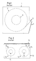
- Figure 1 shows the basic principle design of a conventional single reel cassette. The fact that the cassette housing contains only one single reel of tape, makes it possible to achieve a large tape area in a fairly small cassette.
- 1 references the cassette housing.
- 2 references the tape reel containing the tape wound on hub 5, while 3 references the leader block (the beginning of the tape with a plastic hook that connects to the tape drive).
- the cassette housing 1 has a door 4 which opens to allow the leader block 3 to be pulled out.
- the dual reel cassette is well known in many different versions: 4 mm DAT or DDS cassette, 8 mm videocassette, the Philips audio (Compact) cassette and the VHS video cassette just to name a few.
- the principle of the dual reel cassette is that both tape reels are located within the cassette housing.
- the tape moves from one reel to the other during operations.
- a portion of the tape housing is typically designed to be opened automatically when the cassette is inserted into the tape drive, thereby exposing the tape.
- the drive read/write head, tape capstan spindle(s) and drive tape guides can then move into contact with the tape.
- a section of the tape is actually pulled out of the cassette during insertion into the drive and wrapped partly around the recording heads and over the drive tape guides.
- Dual reel cassettes Compared with the single reel cassette design, the dual reel cassette normally makes it possible to design a fairly simple drive mechanism, especially if the tape does not need to be partly pulled out of the cassette.
- Dual reel cassettes have two openings at the bottom where tape drive motors can engage to the tape reels inside the cassette.
- Figure 2 shows the basic design principles of a dual reel cassette.
- a cassette housing 10 contains a tape 14 wound in reels 12 on respective hubs 11.
- a door 15 which opens during insertion into the drive to expose the front end of the cassette housing 10 and the tape 14.
- a drawback of dual reel cassettes is that the there must be room for more than two full tape reels inside the housing.
- the distance from each hub to the inside of the cassette housing must at a minimum be equal to the maximum radius of a hub fully loaded with tape (plus a small tolerance/safety factor).
- the dual cassette has a capacity for less tape media than a similar single reel cassette with the same form factor.
- the belt driven cassette is a variant of the dual reel cassette.
- the most widely used version is the QIC (quarter inch cartridge) and its smaller companion, the Travan cartridge.
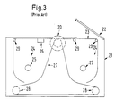
- Figure 3 shows the basic principle of a conventional QIC cartridge.
- a drive puck 20 engages the capstan motor in the tape drive when the cartridge is loaded into the drive.
- a mirror 26 detects special holes at the beginning and end of the tape.
- a belt 28 is entrained around the drive puck 20 and friction rollers 28, and is in contact with both tape packs 24. When the drive motor rotates the drive puck 20, the belt 28 causes the tape 23 to be moved in a straight path defined by guide pins 29.
- the belt driven QIC cartridge is designed so that it is only necessary to use one motor driving the cartridge reels at one point (the drive puck 20 in Figure 3). That can simplify the drive construction even further.
- the belt driven QIC cartridge has the same limitations with respect to available tape length. Actually, because the belt driven cartridge typically needs to have some additional components (belt guides etc.) inside its housing, the available tape length may be less than for a similar dual reel cassette design.
- An object of the present invention is to provide a special form of a dual reel cassette which is as simple to utilize in a tape drive as normal dual reel cassettes, while containing significantly more tape media than a regular dual cassette having the same form factor.
- An apparatus according the preamble of claim 1 is known from US-A- 3 520 495.
- the maximum space occupied by the tape medium on the hubs (which occurs when an equal amount of tape medium is present on each of the hubs) is mathematically minimized. Since the various cassette or cartridge housing formats have standardized dimensions, in order to allow them to interact with other standardized components, such as tape drives, the interior size and volume within the housing is fixed. By minimizing the amount of space which is occupied by the tape contained in the housing on the hubs, in accordance with the invention, a significantly larger amount (length) of tape can be accommodated in standardized housings than was heretofore possible.
- a dual reel cassette format having a standardized wall-to-wall longest dimension of 100 mm
- 900 feet (274 m) of tape medium can be accommodated in such a housing, wound on the two hubs therein.
- a so-called quadrature dual reel cassette having a diagonal (corner-to-corner) dimension of 141 mm
- 1,448 feet (441 m) of tape can be accommodated in such a housing in accordance with the invention.
- the axles on which the two hubs are respectively mounted are both rotationally mounted on a platform.
- the platform is disposed in an opening in, for example, the bottom of the cassette housing.
- the opening is substantially the same width as the platform, but is longer in length, so that the platform can slide along the length (longest dimension) of the opening. Such sliding can be permitted, for example, by a tongue-and-groove engagement between the sides of the platform and the sides of the opening.
- the axles on which the hubs rotate are mounted at fixed positions within the housing, it was always necessary to space the fixed-position hub axle at a distance from the closest housing sidewall so as to leave space for a fully-loaded reel of tape between the axle and the sidewall.
- the maximum spacing which must be maintained between the axles and the respective sidewalls is that distance which is necessary to accommodate the maximum combined space which will be occupied by the two tape reels. This maximum occurs when an equal amount of tape is on each hub.
- the platform automatically slides within the opening, by means of suitable biasing, in a direction toward the sidewall closest to the hub having the lower diameter of tape reeled thereon.
- the platform thus automatically moves away from the sidewall closest to the hub having the largest diameter of tape reeled thereon, thereby increasing the spacing between that hub's axle and the closest sidewall, so as to accommodate the increasing diameter of tape being reeled onto that hub.
- Figure 1 is a schematic illustration showing the basic structure of a conventional single reel cassette.
- Figure 2 is a schematic illustration showing the basic structure of a conventional dual reel cassette with fixed-position axles.
- Figure 3 is a schematic illustration showing the basic structure of a conventional belt-driven dual reel cassette, having fixed-position axles.
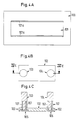
- Figure 4A is a view from above of a base of a cassette housing constructed in accordance with the principles of the present invention.
- Figure 4B is a view from above of a platform insertable into the housing base shown in Figure 4A in accordance with the invention.
- Figure 4C is a sectional view taken along line IVC - IVC in Figure 4B.
- Figure 4D is a sectional view showing the platform of Figure 4B inserted in the base of Figure 4A, in accordance with the invention.
- FIGS 4E, 4F and 4G respectively show various sliding positions of the platform of Figure 4B in the base of Figure 4A, in accordance with the invention.
- Figure 5 is a view from above showing the basic components of a complete cassette constructed in accordance with the principles of the present invention.
- Figures 6A, 6B and 6C show various positions of the sliding platform in the cassette of Figure 5, as tape is transferred between the hubs.
- Figure 7 is a schematic illustration for use in conjunction with a mathematical analysis of the improvement in tape length achievable in accordance with the invention.
- Figure 8 shows one standardized cassette housing format in which the present invention can be used.
- Figure 9 illustrates an alternative manner of accommodating the tape reels in a standardized housing format of the type shown in Figure 8.
- Figure 10 shows a further version of a manner for accommodating the tape reels in a standardized housing of the type shown in Figure 8.
- Figure 11 shows a conventional standardized quadratic cassette housing, with fixed-position axles for the tape hubs.
- Figure 12 is a schematic illustration showing the incorporation of the invention in a standarized quadratic cassette housing.
- Figures 13A and 13B show a cassette constructed in accordance with the principles of the present invention inserted in a tape drive, with the platform respectively in opposite extreme positions.
- Figure 14 shows a cassette constructed in accordance with the principles of the present invention inserted in a different orientation in a tape drive from Figures 13A and 13B.
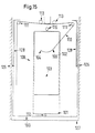
- Figure 15 shows one embodiment of doors on a cassette housing constructed in accordance with the principles of the present invention.
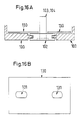
- Figures 16A and 16B respectively show a side view and a plan view, of a plate for covering openings in the base of the cassette housing in a cassette constructed in accordance with the principles of the present invention.
- Figure 17 shows a portion of a cassette constructed in accordance with the principles of the present invention in an embodiment for providing locking of the tape hubs when the cassette is not inserted into a tape drive.
- Figure 18 shows a movable blade embodiment for automatically closing the opening in the base plate of a cassette housing constructed in accordance with the principles of the present invention.
- FIGs 4A through 4D The basic structure of the inventive cassette is shown in Figures 4A through 4D.
- a rectangular opening 101 At the bottom of the cassette housing 100 (see figure 4A) is a rectangular opening 101.
- a platform 102 is inserted into this opening.
- the platform contains two tape reel hubs 103 and 104 as shown in figure 4B. The tape shall be wound on these two hubs.
- FIG. 4C shows the design of the platform and the hubs in more detail, seen from the long side.
- the two hubs 103 and 104 rotate around two tubular guides 107 mounted onto the platform 102.
- Each of the tape hubs 103 and 104 has an internal pin or axle which extends through its tube guide 107 and through a hole at the bottom of the platform. At the bottom, this internal axle or pin is connected to a hub disk 105 or 106. By rotating a hub disk at the bottom of the platform 102, the corresponding hub will rotate on the other side of the platform 102.
- the platform 102 is designed so that it can be inserted into the opening 101 in the cassette housing.
- the width of the platform 102 and the width of the opening 101 are almost the same (just a small difference to allow for tolerance variations), while the length of the platform 102 is shorter than the length of the opening 101.
- the two longer sides of the platform 102 and the two longer sides of the cassette bottom along the opening 101 are designed so that the platform 102 can slide within the opening, as shown in Figure 4D.
- each of the long sides of opening 101 has a tongue 101a which mates in a groove in the platform 102 (of course, the tongues could be on the platform 102 and the grooves in the sides of the opening 101).
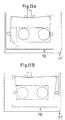
- Figure 4E shows the cassette housing 100 with the platform 102 inserted into the opening 101. As indicated by the arrows, the platform 102 is designed so that it can easily slide from one side to the other within the opening 101.
- Figure 4F shows the cassette with the platform 102 slid all the way to the left, while figure 4G shows the platform 102 positioned all the way to the right (within the opening 101).
- Figure 5 shows the cassette with tape and loaded into a tape drive.
- the platform 102 with the hubs 103 and 104 now has tape on the hubs.
- Tape reel 108 is wound on hub 103 while tape reel 109 wound on hub 104.
- Figure 5 shows more tape on hub 103 than on hub 104.
- the tape 110 goes from one reel (for example 108) to the other reel (109).
- the cassette housing contains two guiding pins 111.
- Two roller pins 112 and 116 are vertically mounted respectively on the left and right sidewalls.
- Figure 5 shows one way of constructing such a door system by having either one or (as in the figure) two sections of the front end cassette wall swing away during insertion.
- Another way of designing such a door opening can be to use a flexible strip covering the front section of the cassette. This strip is then pulled back (along the sidewalls of the cassette), as the cassette is inserted into the drive, thereby exposing the front opening of the cassette.
- two tape guides 113 mounted in the drive at each side of the head engage with the tape and keep it at a stable position.
- the head 114 mounted in the drive also engages the tape, and read and write operations can be performed.
- Figure 5 shows the cassette loaded with almost all the tape on the left hub 103.
- the corresponding tape reel 108 is pressing toward the left side roller pin 112, thereby moving the hub platform 102 to the right in the opening 101 of the cassette house.
- FIGS 6A, 6B and 6C The principle of the operation is shown in Figures 6A, 6B and 6C. These figures are somewhat simplified from Figure 5 in that the head, the head guides and the door(s) are not shown to make the drawings simpler to understand.
- the left tape hub 103 contains a full tape reel and the right hub 104 is empty. This is shown in Figure 6A.
- the platform 102 is positioned all the way to the right in the opening 101 in the cassette housing 100.
- the left tape reel 108 is touching the left side wall roller 112 while the right tape reel is almost touching the right side wall roller 116.
- the drive mechanism (the drive motor(s)) engages the two hub disks 105 and 106 (ref. figure 4C), at the bottom of the cassette housing 100, and thereby can move the tape from one reel to the other.
- the diameter of the left reel 108 diminishes and the right tape reel 109 increases in diameter.
- the right tape reel 109 will press on the side wall roller 116. As this happens, the cassette housing 100 starts moving from left to right relative to the hub platform 102. (See Figure 6B).
- the available area within the tape housing can be utilized better than in conventional designs. Therefore with this design, the width of the cassette housing (the distance between the two sidewalls) can be made shorter than in a conventional dual reel tape cassette with fixed hub positions relative to the cassette housing, or more tape can be loaded into a cassette with fixed dimensions compared to the conventional design with fixed hubs.
- the minimum distance required between the two reel hubs is calculated so that the tape on the two reels never touch as the tape is running from one reel to the other. This minimum distance will vary depending upon how much tape has unwound from the supply reel and wound up on the take-up reel. It is therefore necessary to find the point where the radius of the supply reel plus the radius of the take-up reel is at maximum. In the following, this distance is called D.
- each hub with no tape has a radius R E .
- R F the radius of this reel.
- T Minimum distance between side walls
- Expression (4) assumes that the tape can be packed properly on the reels without any air between the layers. In reality, there will be some air and packing tolerances which will lower the tape length somewhat. This will vary from cassette type to cassette type depending upon the tape itself, tape tension, speed and speed control etc. For this invention analysis, Expression (4) will be used since it is not relevant to bring in the variations in tape length due to tolerances and properties not connected with the present invention.
- the invention makes it possible to get 47% more tape inside a cassette compared with the same cassette without using the invention.
- Figure 9 shows a solution with a double set of rollers 120 at each wall side, mounted to maximize the available space for the tape on the hubs.
- the rollers 120 are each mounted on an arm which can pivot around a pin 124.
- the arm is hooked to a spring 125 so that the rollers 122 constantly press on the tape reel 108 to keep it tight.
- single reel cassettes will always have the maximum available tape length for any specific cassette housing, although the inner hub diameter typically has to be made somewhat larger, thereby reducing the maximum tape length somewhat (compared to theoretical maximum).
- single reel cassettes do have long tape length and typically have a very simple inner structure which makes it possible to reduce the cassette cost.
- Single reel cassettes require a more complex drive mechanism, and the average time to access data will be longer than for systems using cassettes with dual reels or hubs.
- drives using dual reel cassettes can be designed so that it is fairly simple to release the cassette and remove it from the drive in case of power loss.
- Single reel cassettes will normally have some tape loaded inside the drive, and it is impossible or at least very cumbersome to remove the cassette from the drive if power fails.
- cassettes like DLT and 3490 have gained so much popularity, there are many library and automatic cassette handling systems designed for such cassettes. Therefore, it is desirable to design a dual reel cassette based on the inventive structure to be used inside such a quadratic housing.
- the actual tape length for a single reel cassette will obviously vary with design, tape parameters etc.
- the tape thickness is 9.144 ⁇ m.
- the inner radius R E is approximately 21 mm and the outer is approximately 45.5 mm. This gives the number of turns to 2679 according to (5) and the tape length to 1828 (557 m) feet.
- the inner wall-to-wall distance of the DLT cassette is close to 100 mm. Therefore, the example given earlier (ref. Figure 7) of a two hub cassette design with inner wall-to-wall distance of 100 mm will be relevant also if such a design were embodied in the housing of a DLT-like cassette. (Note that a single reel cassette typically needs a larger hub design (larger diameter) to achieve the necessary stability).
- Figure 11 is a design with fixed hubs.
- Figure 12 is a design with the invention.
- T ⁇ 2• ⁇ (R E 2 + R F 2 ) + 2 ⁇ 2R F
- D 2r is given by formulae (1).
- r is the radius of the tape reel when there is an equal amount of tape on both hubs.
- R E 15 mm
- R F is then approximately 38.6 mm in the embodiment of Figure 12.
- the number of turns is 2622 and the available tape length is 441 meters or 1448 feet. Therefore, it is possible to make a chart as shown in Table 1 for the various options assuming the use of DLT-like housing.
- Table 1 compares possible maximum tape length in a square cartridge with 100 mm inner wall-to-wall distance.
- the sliding direction of the platform 102 is substantially parallel to the direction of tape transport; in the embodiment of Figure 12 the sliding direction is oriented at approximately 45° relative to the tape transport directions (along the two sides of the quadratic housing).
- Figures 4 through 12 show various options for implementing the invention.
- the embodiment of Figure 12 is very efficient.
- a non-quadratic solution may be based upon the design shown in Figures 5 and 6.
- the cassette housing When inserted in the drive, the cassette housing will move across the width of the tape drive as shown in Figures 13A and 13B.
- the drive 127 holds the cassette house completely inside the sidewalls with enough room for the cassette house to move within the drive as the tape moves from being all on the left reel ( Figure 13A) to being all on the right reel ( Figure 13B).
- Figure 15 shows the basic design of a cassette made for this kind of operation.
- the cassette housing 100 is locked to the drive 127 when inserted.
- a system with two sliding doors 128 is shown.
- the sliding doors 128 are pulled back by knobs 126 on the side walls of the drive during insertion.
- the sliding doors 128 must be spring-loaded so that they go back to the front of the cassette housing 100 when the cassette is removed from the drive. For simplicity, such springs are not shown in Figure 15).
- the front of the cassette housing 100 When fully inserted, the front of the cassette housing 100 is open, exposing the tape.
- Two tape guides 113 permanently mounted in the drive and the drive head 114, engage the tape.
- the drive tape movement mechanism (typically two motors) engage the hub disks at the bottom of the cassette (ref. Figure 4C).
- the mechanism which moves the tape must be mounted so that it can easily slide in the same direction in/out as the platform 102 in the cassette.
- tape hubs 103 and 104 are mounted on to the platform 102 which can slide in the cassette opening 101.
- Tape 110 moves between tape reels 108 and 109.
- Tape guiding pins 111 ensure proper positioning of the tape to the front of the cassette at all times.
- the vertical rollers 112 and 116 guide the platform 102 inwardly or outwardly depending upon the direction of the tape movement.
- This design therefore allows a very simple and stable interface between the tape and the head in the drive.
- the two hubs 103 and 104 may be placed in the direction of the length of the drive as shown in Figure 15 or they may be placed slightly offset from each other to allow for better utilization of the available area within the cassette housing.
- the total cassette needs to be somewhat longer in order to make room for the tape guiding pins 111, etc.
- the two hubs on which the tape is wound are mounted in the housing so as to be translationally movable, in tandem, in a direction parallel to the housing bottom (or top) as tape is transferred between the hubs.
- Figure 4C shows one principle as already mentioned. For some applications, it may be important to ensure proper locking of the tape hubs (tape reels) when the cassette is not inserted into the tape drive.
- Figure 17 shows one way to achieve this based upon the design shown in Figure 4C.
- a small ball 140 (made of steel or other strong material) lies on the top of each of the tape hubs 103 and 104 and each ball 140 is pressed against the tape hubs by springs 140.
- the spring 140 will press the tape hubs down toward the top of the tubular guide 107.
- the top of this guide and the inside of the tape hub touching it may be provided with a series of small teeth 142 so that it effectively prevents the hub from rotating when the cassette is not loaded into a drive.
- the spring 140 may either be placed under the top cover or it may be made as an integrated part of the platform 102 assembly.
- the drive hub motors engage the hub disk plate and press this upwards. This will press the whole tape hub upwards and the hub can then more freely (controlled by the motor).
Landscapes
- Packaging Of Annular Or Rod-Shaped Articles, Wearing Apparel, Cassettes, Or The Like (AREA)
Claims (11)
- Dispositif pour stocker sous forme de bobine un support continu en bande, comprenant:un boítier (100) ayant une base avec une ouverture (101) entre des parois latérales opposées du boítier;un support continu en bande (110), ayant une première extrémité et une deuxième extrémité;un premier moyeu (103) de bande disposé dans ledit boítier (100) au voisinage immédiat de ladite première extrémité dudit support continu en bande (110);un premier essieu, sur lequel est monté ledit premier moyeu de bande, permettant la rotation dudit premier moyeu (103) de bande;un deuxième moyeu (104) de bande disposé dans ledit boítier (100) au voisinage immédiat de ladite deuxième extrémité dudit support continu en bande (110);un deuxième essieu, sur lequel est monté ledit deuxième moyeu (104) de bande, permettant la rotation dudit deuxième moyeu (104) de bande, les deux essieux étant montés avec un écartement fixe l'un par rapport à l'autre sur une plate-forme (102) disposée de manière à pouvoir coulisser dans lesdites ouvertures (101), des parties respectives dudit support continu en bande (110) étant enroulées sur ledit premier moyeu (103) de bande et sur ledit deuxième moyeu (104) de bande, caractérisé en ce qu'au moins un desdits essieux est entraíné directement; etladite plate-forme (102) permettant un mouvement desdits premier et deuxième essieux montés sur ladite plate-forme sur une ligne droite et parallèlement à ladite base, à mesure que ledit support en bande est transféré entre lesdits premier et deuxième moyeux de bande lors de la rotation desdits premier et deuxième moyeux de bande, ladite plate-forme présentant une forme rectangulaire, et ladite plate-forme (102) étant mise en place par des axes (112, 116) de galets ou des galets (122) disposés entre les parois du boítier (100) se trouvant dans la direction de mouvement de ladite plate-forme et ladite plate-forme (102).
- Dispositif selon la revendication 1, dans lequel ladite plate-forme (102) agencée de manière à pouvoir coulisser comporte un système à rainures et languettes.
- Dispositif selon la revendication 2, dans lequel ledit système à rainures et languettes comprend une première et une deuxième languettes (101a) faisant respectivement saillie depuis lesdites parois parallèles de l'ouverture (101) et une première et une deuxième rainures respectivement situées dans lesdites parois parallèles de la plate-forme, ladite première rainure recevant ladite première languette et ladite deuxième rainure recevant ladite deuxième languette.
- Dispositif selon la revendication 1, dans lequel ledit boítier (100) est rectangulaire.
- Dispositif selon la revendication 1, dans lequel ledit boítier (100) et ladite base sont quadrangulaires.
- Dispositif selon la revendication 1, dans lequel ledit support en bande (110) est transféré dans une direction de transfert entre lesdits premier (103) et deuxième (104) moyeux, et dans lequel ladite plate-forme (102) permet un mouvement de translation desdits premier et deuxième essieux dans une direction oblique à environ 45° par rapport à ladite direction de transfert de bande.
- Dispositif selon l'une quelconque des revendications précédentes, comprenant en outre un capot (130), disposé dans ledit boítier (100) sur ladite base, ayant des ouvertures à travers lesquelles lesdits premier et deuxième essieux font respectivement saillie et se déplacent à mesure que ladite plate-forme (102) exécute ledit mouvement de translation, ledit capot (130) couvrant ladite ouverture (101) ménagée dans ladite base.
- Dispositif selon l'une quelconque des revendications précédentes, dans lequel ladite ouverture (101) a des extrémités parallèles disposées d'une manière mutuellement opposée entre lesdits côtés parallèles de ladite ouverture (101), et ledit dispositif comprend en outre, à chacune desdites extrémités, une première et une deuxième lames (150, 151) montées de manière à pouvoir tourner autour d'un point de pivotement commun situé sur ladite base, un moyen de sollicitation (153) pour pousser normalement lesdites lames l'une vers l'autre afin de couvrir une partie de ladite ouverture (101), et lesdites lames étant écartées l'une de l'autre par un desdits essieux lorsque ledit moyen de support (102) exécute ledit mouvement de translation.
- Dispositif selon l'une quelconque des revendications précédentes, comprenant en outre un moyen pour empêcher temporairement lesdits premier (103) et deuxième (104) moyeux de bande de tourner respectivement sur les premier et deuxième essieux.
- Dispositif selon l'une quelconque des revendications précédentes, dans lequel chacun desdits moyeux (103, 104) a un rayon d'environ 15 mm.
- Dispositif selon l'une quelconque des revendications précédentes, comprenant un boítier carré (100) ayant une dimension en diagonale d'environ 141 mm, et contenant au moins 441, 35 m (1 448 ") de support continu en bande enroulé sur les premier (103) et deuxième (104) moyeux rotatifs dans ledit boítier (100).
Applications Claiming Priority (2)
| Application Number | Priority Date | Filing Date | Title |
|---|---|---|---|
| US940068 | 1978-09-07 | ||
| US08/940,068 US5908168A (en) | 1997-09-29 | 1997-09-29 | Apparatus for storing an increased length of continuous tape medium in reeled form in standardized housing formats |
Publications (2)
| Publication Number | Publication Date |
|---|---|
| EP0905696A1 EP0905696A1 (fr) | 1999-03-31 |
| EP0905696B1 true EP0905696B1 (fr) | 2000-08-02 |
Family
ID=25474171
Family Applications (1)
| Application Number | Title | Priority Date | Filing Date |
|---|---|---|---|
| EP97120743A Expired - Lifetime EP0905696B1 (fr) | 1997-09-29 | 1997-11-26 | Dispositif pour le stockage d'une plus grande longueur de bande en forme de bobine dans des boítiers standarisés |
Country Status (3)
| Country | Link |
|---|---|
| US (1) | US5908168A (fr) |
| EP (1) | EP0905696B1 (fr) |
| DE (1) | DE69702712T2 (fr) |
Families Citing this family (3)
| Publication number | Priority date | Publication date | Assignee | Title |
|---|---|---|---|---|
| US6305631B1 (en) * | 1999-09-28 | 2001-10-23 | Imation Corp. | Tape cartridge with remove to operate tape and hubs |
| EP1363289A1 (fr) * | 2002-05-14 | 2003-11-19 | Tandberg Data ASA | Cassette et unité à bande pour bande extrèmement large |
| US7327534B2 (en) * | 2004-09-01 | 2008-02-05 | Sony Corporation | Ultra fast backup (UFB) tape cartridge and method for loading same |
Family Cites Families (11)
| Publication number | Priority date | Publication date | Assignee | Title |
|---|---|---|---|---|
| US1317404A (en) * | 1919-09-30 | thomas | ||
| US1244918A (en) * | 1914-12-28 | 1917-10-30 | Thomas Oberkirch Company Ltd | Reeling apparatus for moving-picture cameras. |
| DE1001013B (de) * | 1954-07-31 | 1957-01-17 | Ernst Maestling Fa | Kassette fuer das Magnettonband von Magnettongeraeten |
| FR1141427A (fr) * | 1954-07-31 | 1957-09-02 | Ernst Mastling | Dispositif de reproduction pour rubans magnétiques acoustiques |
| GB1108198A (en) * | 1965-06-29 | 1968-04-03 | Tadashi Sotani | A magazine for reel-form strip material |
| US3520495A (en) * | 1966-10-29 | 1970-07-14 | Tadashi Sotani | Tape cartridge and driving mechanism for the tape |
| DE2937396A1 (de) * | 1979-09-15 | 1981-04-02 | Basf Ag, 6700 Ludwigshafen | Magnetbandkassette und magnetbandgeraet |
| DE3025536C2 (de) * | 1980-07-05 | 1984-10-25 | Grundig E.M.V. Elektro-Mechanische Versuchsanstalt Max Grundig, 8510 Fürth | Magnetbandkassette |
| JPS60154384A (ja) * | 1984-01-25 | 1985-08-14 | Victor Co Of Japan Ltd | テ−プカセツト |
| JPH03283158A (ja) * | 1990-03-30 | 1991-12-13 | Sony Corp | テープカセット |
| US5547142A (en) * | 1994-12-30 | 1996-08-20 | Storage Technology Corporation | Tape cassette with internal tape cleaning and locking |
-
1997
- 1997-09-29 US US08/940,068 patent/US5908168A/en not_active Expired - Fee Related
- 1997-11-26 EP EP97120743A patent/EP0905696B1/fr not_active Expired - Lifetime
- 1997-11-26 DE DE69702712T patent/DE69702712T2/de not_active Expired - Lifetime
Also Published As
| Publication number | Publication date |
|---|---|
| EP0905696A1 (fr) | 1999-03-31 |
| DE69702712D1 (de) | 2000-09-07 |
| US5908168A (en) | 1999-06-01 |
| DE69702712T2 (de) | 2000-11-23 |
Similar Documents
| Publication | Publication Date | Title |
|---|---|---|
| GB2089317A (en) | Miniature type tape cassette and adapter | |
| EP1746592A2 (fr) | Lecteur de bande avec parcours de bande amélioré et procédés associés | |
| NL8105305A (nl) | Aanpasstuk voor een miniatuur bandcassette. | |
| EP0929071B1 (fr) | Cartouche à bandes multiples et système d'entraínement dans lequel les bandes sont extraites de la cartouche | |
| US6267313B1 (en) | Wide tape cartridge | |
| JPH0743904B2 (ja) | テ−プ・カ−トリツジ | |
| EP0905696B1 (fr) | Dispositif pour le stockage d'une plus grande longueur de bande en forme de bobine dans des boítiers standarisés | |
| EP0214820B1 (fr) | Cartouche pour bande magnétique | |
| US5777819A (en) | Magnetic tape cassette | |
| KR940011094B1 (ko) | 디스크 드라이브 겸용 자기테이프 카트리지 | |
| US6206313B1 (en) | Tape cartridge allowing concurrent reading/writing on multiple tapes | |
| US6522500B1 (en) | Tape cartridge for extremely wide tape having an access opening allowing extraction of tape, and tape drive for use therewith | |
| US5963395A (en) | Multi-tape cartridge and multi-head drive for concurrent data transfer to/from multiple tapes | |
| US20090180214A1 (en) | Tape cartridge with built-in reel motors | |
| US7227716B2 (en) | Two tape, four reel cartridge and drive for wide magnetic recording tape | |
| JP4011992B2 (ja) | 記録テープカートリッジ | |
| US6450434B1 (en) | Wide tape holding frame | |
| EP0557726B1 (fr) | Lecteur de cassette à bande compatible avec des cassettes à bande de différent format | |
| EP0506459B1 (fr) | Lecteur à cassettes | |
| US7395982B2 (en) | Cartridge reel centering device | |
| JPH1011853A (ja) | 記録再生装置 | |
| JP2003157651A (ja) | 記録テープカートリッジ | |
| US20080185471A1 (en) | Aligning tape winding in tape cartridge | |
| US5777830A (en) | Belt-driven tape cartridge having increased tape capacity | |
| US4888659A (en) | Tape cartridge for use in disc drive |
Legal Events
| Date | Code | Title | Description |
|---|---|---|---|
| PUAI | Public reference made under article 153(3) epc to a published international application that has entered the european phase |
Free format text: ORIGINAL CODE: 0009012 |
|
| AK | Designated contracting states |
Kind code of ref document: A1 Designated state(s): DE |
|
| AX | Request for extension of the european patent |
Free format text: AL;LT;LV;MK;RO;SI |
|
| 17P | Request for examination filed |
Effective date: 19990312 |
|
| 17Q | First examination report despatched |
Effective date: 19990506 |
|
| GRAG | Despatch of communication of intention to grant |
Free format text: ORIGINAL CODE: EPIDOS AGRA |
|
| AKX | Designation fees paid |
Free format text: DE |
|
| GRAG | Despatch of communication of intention to grant |
Free format text: ORIGINAL CODE: EPIDOS AGRA |
|
| GRAH | Despatch of communication of intention to grant a patent |
Free format text: ORIGINAL CODE: EPIDOS IGRA |
|
| GRAH | Despatch of communication of intention to grant a patent |
Free format text: ORIGINAL CODE: EPIDOS IGRA |
|
| GRAA | (expected) grant |
Free format text: ORIGINAL CODE: 0009210 |
|
| AK | Designated contracting states |
Kind code of ref document: B1 Designated state(s): DE |
|
| REF | Corresponds to: |
Ref document number: 69702712 Country of ref document: DE Date of ref document: 20000907 |
|
| EN | Fr: translation not filed | ||
| PLBE | No opposition filed within time limit |
Free format text: ORIGINAL CODE: 0009261 |
|
| STAA | Information on the status of an ep patent application or granted ep patent |
Free format text: STATUS: NO OPPOSITION FILED WITHIN TIME LIMIT |
|
| 26N | No opposition filed | ||
| PGFP | Annual fee paid to national office [announced via postgrant information from national office to epo] |
Ref country code: DE Payment date: 20161201 Year of fee payment: 20 |
|
| REG | Reference to a national code |
Ref country code: DE Ref legal event code: R071 Ref document number: 69702712 Country of ref document: DE |