EP0905451A1 - Anordnung eines atmosphärischen Gasbrenners in einer Kochmulde mit einer Kochfläche aus Glaskeramik - Google Patents
Anordnung eines atmosphärischen Gasbrenners in einer Kochmulde mit einer Kochfläche aus Glaskeramik Download PDFInfo
- Publication number
- EP0905451A1 EP0905451A1 EP98116932A EP98116932A EP0905451A1 EP 0905451 A1 EP0905451 A1 EP 0905451A1 EP 98116932 A EP98116932 A EP 98116932A EP 98116932 A EP98116932 A EP 98116932A EP 0905451 A1 EP0905451 A1 EP 0905451A1
- Authority
- EP
- European Patent Office
- Prior art keywords
- burner
- arrangement according
- molded body
- hob
- gas burner
- Prior art date
- Legal status (The legal status is an assumption and is not a legal conclusion. Google has not performed a legal analysis and makes no representation as to the accuracy of the status listed.)
- Granted
Links
Images




Classifications
-
- F—MECHANICAL ENGINEERING; LIGHTING; HEATING; WEAPONS; BLASTING
- F24—HEATING; RANGES; VENTILATING
- F24C—DOMESTIC STOVES OR RANGES ; DETAILS OF DOMESTIC STOVES OR RANGES, OF GENERAL APPLICATION
- F24C3/00—Stoves or ranges for gaseous fuels
- F24C3/08—Arrangement or mounting of burners
- F24C3/085—Arrangement or mounting of burners on ranges
Definitions
- the invention relates to an arrangement of an atmospheric gas burner in a hob with a frame, and a hob with a Shaped body made of glass ceramic, glass or ceramic as a cooking surface, in which for Recording at least one burner at least one opening is formed.
- gas hobs with a plate-shaped molded body made of glass ceramic, glass or ceramic as a cooking surface, whether as part of a hob or a gas stove.
- gas radiation burners are provided under a continuous hob, in which the gas supplied together with air is burned on the surface of a burner plate made of porous ceramic.
- atmospheric gas burners ie burners with an open flame, are integrated in corresponding openings in the cooking surface.
- a gas hob is known from German patent DE 44 42 572 C1 with a plate-shaped body made of brittle material, in which to hold at least one atmospheric gas burner at least one opening is formed by means of a metallic sleeve is bordered at a distance, which the molded body in the edge region of With the interposition of sealants, it grips around on both sides in the manner of a union and which is an abutment for which is placed in the free opening of the cuffs Forms gas burner.
- the German published application DE 41 33 409 A1 shows a burner arrangement, for example for hobs where at least one gas burner is in one Carrier frame attached and the surrounding surface of the gas burner covered by a plate-shaped body made of brittle material is, each gas burner through an opening in the molded body extends over the top and between the molded body and each Gas burner with a permanently elastic connection and sealing device a firm and liquid-tight on the edge area of the opening and at least a connecting surface and sealing element formed by the gas burner is attached, the gas burner being separated from the Shaped body is worn and between the gas burner and the support frame Securing and holding devices are attached if the molded body breaks and thus the loss of its load-bearing capacity with the admission of limited mobility Regarding retention and torsion protection for each of the gas burners are effective.
- the invention is therefore based on the object, the arrangement of an atmospheric To design gas burner in a gas hob so that under Attention to the special requirements that a glass ceramic, glass or Ceramic surface to the construction of a hob, a simple, inexpensive Possibility of assembly and disassembly especially of the gas burner is specified.
- the arrangement is intended to enable easy assembly during manufacture and disassembly in the event of service, it being particularly important that the appliance be set up without "overhead installation” and that servicing can be carried out without disassembling the cooking appliance from the worktop.
- This part of the task is particularly important for the economical consideration of such solutions, since the simple assembly from above can on the one hand reduce the production costs considerably and on the other hand the times for maintenance in the event of service can be significantly reduced.
- Another object of the invention is also burners with different geometries, as they are available on the market, with glass ceramic, glass or ceramic cooktops to be able to use.
- the object is achieved according to the invention in that the arrangement the burner by means of a multi-part construction, the parts of which in Clamping area of the opening on the molded body from above and below apply under pressure, with part of the structure the molded body from above as a sleeve using sealants - ring disk or frame-shaped - overlaps and the edge of the free inner area of the cuff forms an abutment for the gas burner, and being another part the construction of the molded body from below by means of a resilient metallic Element that attaches as a bearing and the bottom of the molded body has as an abutment, engages and where the resilient element Force exerts the gas burner by pressing the seal against the molded body presses.
- the part of the construction which overlaps the shaped body as a collar in the form of a ring disk or frame and forms an abutment for the gas burner in a directly detachable manner, in particular screwed, to the burner.
- the connection is made via a flange-like projection which is formed on the burner, this projection having a smaller diameter than the opening in the molded body, but a larger diameter than the diameter of the inner region of the sleeve of the part of the construction which extends above.
- the resilient is attached metallic element of the part of the construction that forms the molded body engages between the one with the flange-like projection of the burner connected cuff.
- the resilient metallic element is attached to a crossbar which is positively connected to the frame of the hob, the crossbar being hung in tabs which are provided in the hob.
- the burner has a Another resilient element and / or via guide bolts that are on the floor support the hob and from below against the cuff of the part of the Construction of the molded body held over from above, positioned and is pressed.
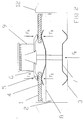
- Figure 1 is the arrangement of a gas burner 9, here in the special form a so-called pot burner on a glass or glass ceramic cooktop 1 shown.
- the burner 9 and the sleeve 6 are a screw as a connecting element 10 screwed against each other.
- Burner 9 and cuff 6 causes that attached to the underside of the burner 9 Spring 4 a force F in the opposite direction to the glass or Glass ceramic hob 1. Against this spring force, the burner 9 with the assembled sealing washer 5 to the glass or glass ceramic cooktop 1 pressed.
- the gas burner / glass ceramic cooktop system is therefore mechanically different Hob 3 decoupled.
- the glass ceramic hob 1 or on the gas burner 9 consequently no leverage can arise, which are caused by rigidly mounted components of the hob 3, the rest on the underside of the glass ceramic hob 1 or in very little Distance. These forces can be exceeded when the maximum Resilience of material lead to breakage.
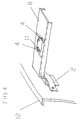
- FIGS. 2, 3 and 4 show the arrangement of another, further gas burner 9 shown on the glass ceramic cooktop 1.
- Central component of this arrangement is the traverse 8, which is in tabs 2 in the frame of the cooking device 12 is mounted.
- a bracket 11 On this crossmember 8 is a bracket 11 the cuff 6 attached.
- Traverse 8, mounting bracket 11 and sleeve 6 are releasably connected to one another via screw connections 10.
- a gas burner 9 on a glass ceramic cooktop 1 is to prevent the penetration of liquids and overcooked goods into the interior of the appliance.
- a spring element 4 is mounted on the cross member 8. By screwing the sleeve 6 against the crossbar 8, the spring element 4 is pressed against the underside of the glass ceramic hob 1.
- the components cuff 6, seal 5, glass ceramic cooktop 1 and crossbar 8 are pressed together with the force F D.
- the seal 5 between the collar 6 and the glass ceramic cooking surface 1 is pressed and thus reliably prevents the overcooking material from entering the cooking appliance.
- the burner 9 is spring 7 against another spring element Cuff 6 pressed. This resilient mounting of the burner 9 ensures mechanical decoupling of the gas burner / glass ceramic system. In the event of a blow to the glass ceramic hob 1 or to the burner 9 consequently no leverage is created by rigidly mounted components of the Cooking hob 3 were caused on the underside of the glass ceramic cooktop 1 fit or are very close. These powers could exceed the maximum material load Break.
- FIG. 5 shows a further possibility of arranging a gas burner 9 on the Glass ceramic hob 1 shown according to the invention.
- Central element in this arrangement is a specially shaped spring 4.
- the storage of this spring 4 takes place in two circumferential points of contact.
- point B is the spring 4 with the burner 9 and the sleeve 6 connected via a detachable screw connection 10.
- These components create a spring tension in the direction of the glass ceramic cooktop 1.
- the force F is in a line of action with the Seal 5 and the sleeve 6.
- This arrangement prevents the one hand Occurrence of bending stresses in the glass ceramic cooktop 1 and reduced thus the risk of breakage. On the other hand, it ensures that the Seal 5 with the glass ceramic hob 1. By pressing this Seal 5 is a penetration of overcooked goods into the interior of the cooking device safely prevented.
- This embodiment also has the advantage that the gas burner / glass ceramic system is mechanically decoupled from the hob 3. in case of a Impact on the glass ceramic hob 1 or on the gas burner 9 can consequently no leverage is created by rigidly mounted components of the Cooking hob 3 could be caused on the underside of the glass ceramic surface 1 fit or are at a short distance.
- the spring 4 can be designed as a closed spring or as a segment-like spring be.
- the burner 9 is attached to a crossbar 8 which is mounted on coil springs 15. With this assembly device, the burner body 9 raised and centered. The screw connection of the components in the This will make attachment point B easier.
- the coil spring 15 is replaced by guide pin 18. This Simplified form of the assembly device ensures centering of the burner 9 and thus also facilitates the screwing of the components in point B.
- This arrangement of a gas burner 9 on a glass ceramic hob 1 - with the 2 embodiments of the assembly devices - is characterized by assembly from above and does not require "overhead installation". This simplifies both assembly during production and maintenance in the case of repairs and servicing, since the connections are loosened from above can be done.
Landscapes
- Engineering & Computer Science (AREA)
- Chemical & Material Sciences (AREA)
- Combustion & Propulsion (AREA)
- Mechanical Engineering (AREA)
- General Engineering & Computer Science (AREA)
- Gas Burners (AREA)
Abstract
Description
Bei der einen Version sind unter einem durchgehenden Kochfeld Gasstrahlungsbrenner vorgesehen, bei denen das zusammen mit Luft zugeführte Gas an der Oberfläche einer aus poröser Keramik bestehenden Brennerplatte verbrannt wird.
Bei einer zweiten Version, von der auch die Erfindung ausgeht, sind atmosphärische Gashrenner, d.h. Brenner mit offener Flamme in entsprechenden Öffnungen der Kochfläche integriert.
Es besteht daher die Notwendigkeit zum Schutze der Glaskeramik-, Glas oder Keramikfläche diese von der Kochmulde und vom Gasbrenner mechanisch zu entkoppeln.
Desweiteren haben alle bekannte Lösungen den Nachteil, daß die Kochgeräte durch aufwendige "Überkopfmontage" gefertigt werden müssen. Dies erhöht die Produktionskosten erheblich.
Bedingt durch diese "Überkopfmontage" ist auch die Wartung im Servicefall sehr aufwendig und erfordert einen Ausbau des Gerätes aus der Arbeitsfläche und die Demontage des gesamten Gerätes sofern dies - bedingt durch die teilweise verwendeten Verklebungen - überhaupt möglich ist. Diese zeitintensive Wartung im Servicefall verursacht ebenfalls sehr hohe Kosten.
Dieser Teilbereich der Aufgabe ist besonders für die wirtschaftliche Betrachtung derartiger Lösungen sehr wichtig, da durch eine einfache Montage von oben zum einen die Produktionskosten erheblich gesenkt werden können, und zum anderen die Zeiten für eine Wartung im Servicefall deutlich reduziert werden können.
Die Verbindung erfolgt dabei über einen flanschartigen Vorsprung, der am Brenner ausgebildet ist, wobei dieser Vorsprung einen kleineren Durchmesser aufweist als die Öffnung im Formkörper, aber einen größeren Durchmesser als der Durchmesser des inneren Bereichs der Manschette des oben übergreifenden Teiles der Konstruktion.
Um der Anordnung einen festen Sitz zu geben ist es vorteilhaft, die Manschette des übergreifenden Teiles lösbar fest mit der Traverse zu verbinden. Dies geschieht vorteilhafterweise über verschraubte Befestigungswinkel.
- Figur 1
- Die Anordnung eines Topf-Brenners zu einer Glas- oder Glaskeramikkochfläche, in einer schematischen Schnittdarstellung
- Figur 2
- Die Anordnung eines anderen Gasbrenners zu einer Glas- oder Glaskeramikkochfläche, in einer schematischen Schnittdarstellung in Frontansicht
- Figur 3
- Die Anordnung des Gasbrenners nach Figur 2 zu einer Glas- oder Glaskeramikkochfläche, in schematischer Schnittdarstellung in Seitenansicht
- Figur 4
- Die Anordnung eines Gasbrenners zu einer Glas- oder Glaskeramikkochfläche mit Hilfe einer Traverse, die eine Aussparung für die Brennerdurchführung aufweist, ebenfalls in einer schematische Darstellung
- Figur 5
- Anordnung eines Gasbrenners zu einer Glas- oder Glaskeramikkochfläche in einer weiteren bevorzugten Ausführungsform der Anordnung
- Figur 6
- Anordnung eines Gasbrenners zu einer Glas- oder Glaskeramikkochfläche in einer weiteren anderen bevorzugten Ausführungsform der Anordnung, in schematischer Schnittdarstellung
- 1
- Formkörper aus Glaskeramik, Glas oder Keramik
- 2
- Laschen (im Rahmen des Kochgerätes 12)
- 3
- Kochmulde
- 4
- federndes metallisches Element
- 5
- Dichtung
- 6
- Manschette (des übergreifenden Teiles der Konstruktion 16)
- 7
- Feder
- 8
- Traverse
- 9
- Brenner
- 10
- Verbindungselement (Schraube)
- 11
- Befestigungsmittel
- 12
- Kochgerät mit Muldenrahmen
- 13
- untergreifender Teil der Konstruktion
- 14
- Öffnung im Formkörper 1
- 15
- Spiral (feder)
- 16
- übergreifender Teil der Konstruktion
- 17
- Brennerflansch
- 18
- Führungsbolzen
Claims (18)
- Anordnung eines atmosphärischen Gasbrenners in einer Kochmulde mit einem Rahmen, und einem Kochfeld mit einem Formkörper aus Glaskeramik, Glas oder Keramik als Kochfläche, in welchem zur Aufnahme mindestens eines Brenners mindestens eine Öffnung ausgebildet ist
dadurch gekennzeichnet,
daß die Anordnung des Brenners(9) mittels einer mehrteiligen Konstruktion erfolgt, deren Teile im Randbereich der Öffnung(14) an dem Formkörper(1) von oben und unten klemmend unter Druck anliegen, wobei ein Teil der Konstruktion(16) den Formkörper(1) von oben als Manschette(6) unter Einsatz von Dichtungsmitteln(5) ringscheiben- oder rahmenförmig übergreift, und der Rand des freibleibenden inneren Bereichs der Manschette(6) ein Widerlager für den Gasbrenner(9) bildet, und wobei ein anderer Teil der Konstruktion(13) den Formkörper(1) von unten mittels eines federnden metallischen Elements(4), das eine Befestigung als Lager und die Unterseite des Formkörpers(1) als Widerlager hat, untergreift und wobei das federnde Element(4) eine Kraft(F) ausübt, die den Gasbrenner(9) unter Anpressen der Dichtung(5) an den Formkörper(1) drückt. - Anordnung nach Anspruch 1,
dadurch gekennzeichnet,
daß der Teil der Konstruktion(16), der den Formkörper(1) von oben als Manschette(6) übergreift und der Teil der Konstruktion(13), der den Formkörper(1) von unten untergreift, den Formkörper(1) gegenüberliegend greifen. - Anordnung nach Anspruch 1,
dadurch gekennzeichnet,
daß der Teil der Konstruktion(16), der den Formkörper(1) ringscheiben- oder rahmenförmig als Manschette(6) von oben übergreift und so ein Widerlager für den Gasbrenner(9) bildet mit dem Brenner(9) direkt lösbar fest verbunden, insbesondere über ein Verbindungselement(10) verschraubt, ist. - Anordnung nach Anspruch 3,
dadurch gekennzeichnet,
daß die Verbindung mittels eines flanschartigen Vorsprungs(17) am Brenner(9) erfolgt. - Anordnung nach Anspruch 4,
dadurch gekennzeichnet,
daß der flanschartige Vorsprung(17) des Brenners(9) einen kleineren Durchmesser hat als die Öffnung(14) im Formkörper(1). - Anordnung nach den Ansprüchen 4 und 5,
dadurch gekennzeichnet,
daß der flanschartige Vorsprung(17) des Brenners(9) einen größeren Durchmesser hat, als der Durchmesser des inneren Bereichs der Manschette(6) des oben übergreifenden Teils der Konstruktion(16). - Anordnung nach den Ansprüchen 1 bis 6,
dadurch gekennzeichnet,
daß die Befestigung des federnden metallischen Elements(4) des Teiles der Konstruktion(13), das den Formkörper(1) untergreift an der Unterseite des Gasbrenners(9) selbst erfolgt. - Anordnung nach den Ansprüchen 1 bis 6,
dadurch gekennzeichnet,
daß die Befestigung des federnden metallischen Elements(4) des Teiles der Konstruktion(13), das den Formkörper(1) untergreift, zwischen der mit dem flanschartigen Vorsprung(17) des Brenners(9) verbundenen Manschette(6) erfolgt. - Anordnung nach den Ansprüchen 1 bis 6,
dadurch gekennzeichnet,
daß die Befestigung des federnden metallischen Elements(4) an einer Traverse(8) erfolgt, die formschlüssig mit dem Rahmen(12) der Kochmulde(3) verbunden ist. - Anordnung nach einem der Ansprüche 7 bis 9,
dadurch gekennzeichnet,
daß das federnde metallische Element(4) tellerförmig ausgebildet ist und den Formkörper(1) in einer kreislinienförmigen Spur untergreift. - Anordnung nach einem der Ansprüche 7 bis 9,
dadurch gekennzeichnet,
daß das federnde metallische Element(4) streifenförmg ausgebildet ist und den Formkörper(1) an mindestens zwei Stellen in der Breite des federnden Elements(4) untergreift. - Anordnung nach Anspruch 11,
dadurch gekennzeichnet,
daß mehrere streifenförmig ausgebildete Elemente(4) in, insbesondere symmetrischen Anordnungen zueinander den Formkörper(1) untergreifen. - Anordnung nach Anspruch 9,
dadurch gekennzeichnet,
daß das federnde metallische Element(4) und/oder weitere Befestigungsmittel(11) aus der Traverse(8) selbst gebildet, insbesondere gebogen sind. - Anordnung nach Anspruch 9,
dadurch gekennzeichnet,
daß die Traverse(8) in Laschen(2), die im Rahmen(12) der Kochmulde(3) vorgesehen sind, eingehängt ist. - Anordnung nach Anspruch 9,
dadurch gekennzeichnet,
daß die Traverse(8) gegenüber dem Rahmen(12) der Kochmulde(3) in vertikaler Richtung federnd beweglich ist. - Anordnung nach den Ansprüchen 9 und 13,
dadurch gekennzeichnet,
daß die Manschette(6) des übergreifenden Teils der Konstruktion(16) lösbar fest mit der Traverse(8) mittelbar verbunden ist. - Anordnung nach Anspruch 16,
dadurch gekennzeichnet,
daß die mittelbare Verbindung über verschraubte Befestigungswinkel(11) erfolgt. - Anordnung nach mindestens einem oder mehreren der vorhergehenden Ansprüche,
dadurch gekennzeichnet,
daß der Gasbrenner(9) über mindestens ein weiteres federndes Element(7), und/oder über Führungsbolzen(18), die sich am Boden der Kochmulde(3) abstützen von unten gegen die Manschette(6) des Teils der Konstruktion(16), der den Formkörper(1) von oben übergreift, gehalten, positioniert und gedrückt ist.
Applications Claiming Priority (2)
| Application Number | Priority Date | Filing Date | Title |
|---|---|---|---|
| DE19742792 | 1997-09-27 | ||
| DE19742792A DE19742792C1 (de) | 1997-09-27 | 1997-09-27 | Anordnung eines atmosphärischen Gasbrenners in einer Kochmulde mit einer Kochfläche aus Glaskeramik |
Publications (2)
| Publication Number | Publication Date |
|---|---|
| EP0905451A1 true EP0905451A1 (de) | 1999-03-31 |
| EP0905451B1 EP0905451B1 (de) | 2003-06-04 |
Family
ID=7843884
Family Applications (1)
| Application Number | Title | Priority Date | Filing Date |
|---|---|---|---|
| EP98116932A Expired - Lifetime EP0905451B1 (de) | 1997-09-27 | 1998-09-08 | Atmosphärischer Gasbrenner mit einer Kochmulde mit einer Kochfläche aus Glaskeramik |
Country Status (5)
| Country | Link |
|---|---|
| US (1) | US6032662A (de) |
| EP (1) | EP0905451B1 (de) |
| DE (2) | DE19742792C1 (de) |
| ES (1) | ES2197402T3 (de) |
| PL (1) | PL328841A1 (de) |
Cited By (2)
| Publication number | Priority date | Publication date | Assignee | Title |
|---|---|---|---|---|
| WO2004001295A1 (en) * | 2002-06-25 | 2003-12-31 | Sami Srl | Gas burner |
| WO2020136254A1 (en) * | 2018-12-27 | 2020-07-02 | Arcelik Anonim Sirketi | A cooking device |
Families Citing this family (18)
| Publication number | Priority date | Publication date | Assignee | Title |
|---|---|---|---|---|
| DE19819732C1 (de) * | 1998-05-02 | 1999-08-26 | Schott Glas | Anordnung zur Befestigung eines atmosphärischen Gasbrenners an der Brenneröffnung einer Kochfläche aus Glas oder Glaskeramik sowie Kochfeld mit einer solchen Anordnung |
| DE19820444A1 (de) * | 1998-05-07 | 1999-11-11 | Bsh Bosch Siemens Hausgeraete | Federnde Gas-Brenner-Lagerung |
| DE19907273A1 (de) * | 1999-02-20 | 2000-08-31 | Ega Engineering Gmbh | Gasbrenner mit Simmerbrenner |
| US6173708B1 (en) * | 1999-11-15 | 2001-01-16 | Maytag Corporation | Gas burner mounting assembly for appliance with ceramic based cooktop |
| DE20016145U1 (de) | 2000-09-18 | 2001-01-18 | Schott Glas, 55122 Mainz | Kochfeld mit mindestens einem atmosphärischen Gasbrenner |
| DE20016506U1 (de) * | 2000-09-23 | 2000-12-07 | EGA Engineering GmbH, 58119 Hagen | Zweikreisbrenner mit Brennerring und Mittenbrenner |
| US6817355B1 (en) | 2003-06-13 | 2004-11-16 | Maytag Corporation | Gas burner mounting assembly for a cooking appliance having a ceramic-based cooktop |
| US20050095547A1 (en) * | 2003-10-31 | 2005-05-05 | Pottenger John T. | Burner assembly and cooktop including same |
| MY144248A (en) * | 2004-10-28 | 2011-08-29 | Electrolux Ab | Improved cooking gas burner |
| US7881593B2 (en) * | 2007-11-16 | 2011-02-01 | Cfom Inc. | Gas cooking appliance with removable burners and useable work area |
| ES2387152B1 (es) * | 2008-09-22 | 2013-07-17 | Bsh Electrodomesticos España, S.A | Bandeja de coccion a gas |
| EP2292978B1 (de) * | 2009-09-03 | 2015-01-28 | BSH Bosch und Siemens Hausgeräte GmbH | Kochfeld, insbesondere Gaskochfeld, sowie Verfahren zur Montage des Kochfeldes |
| EP2295868B1 (de) | 2009-09-09 | 2016-10-26 | BSH Hausgeräte GmbH | Gaskochfeld sowie Gasherd mit diesbezüglichem Gaskochfeld |
| ITTO20111191A1 (it) * | 2011-12-22 | 2013-06-23 | Indesit Co Spa | Piano di cottura, in particolare ad uso domestico |
| US9784454B2 (en) | 2013-03-14 | 2017-10-10 | Whirlpool Corporation | Cooktop burner mounting system |
| US10401034B2 (en) * | 2016-03-22 | 2019-09-03 | Haier Us Appliance Solutions, Inc. | Illuminated cooktop burner appliance |
| US10935247B2 (en) * | 2017-09-29 | 2021-03-02 | Lg Electronics Inc. | Cooking apparatus |
| US11234556B2 (en) | 2017-10-13 | 2022-02-01 | Lg Electronics Inc. | Cooking apparatus |
Citations (7)
| Publication number | Priority date | Publication date | Assignee | Title |
|---|---|---|---|---|
| US5046477A (en) | 1990-12-28 | 1991-09-10 | Amana Refrigeration Inc. | Gas cook-top with glass top |
| EP0536619A1 (de) * | 1991-10-09 | 1993-04-14 | Schott Glaswerke | Anordnung mindestens eines Gasbrenners in einem Fremdkörper aus sprödbrüchigem Material, beispielsweise für Kochmulden |
| US5266026A (en) * | 1990-10-17 | 1993-11-30 | Robertshaw Controls Company | Burner construction and method of making the same |
| DE4442572C1 (de) | 1994-11-30 | 1995-09-28 | Schott Glaswerke | Vorrichtung zum Schutz der Ränder von Öffnungen in Formenkörpern aus Glaskeramik, Glas oder Keramik |
| DE19505469C1 (de) * | 1995-02-17 | 1996-02-08 | Schott Glaswerke | Anordnung für die Zuführung von Primärluft zu einem atmosphärischen Gasbrenner über einer Kochplatte aus Glaskeramik |
| US5623917A (en) * | 1995-12-21 | 1997-04-29 | White Consolidated Industries, Inc. | Sealed burner assembly |
| DE29702649U1 (de) * | 1997-02-15 | 1998-06-18 | EGA Engineering GmbH, 58119 Hagen | Gasbrenner für flache Kochmulden |
Family Cites Families (2)
| Publication number | Priority date | Publication date | Assignee | Title |
|---|---|---|---|---|
| US4971024A (en) * | 1990-02-06 | 1990-11-20 | New World Domestic Appliances Limited | Cooking hobs |
| DE19633141C1 (de) * | 1996-08-16 | 1997-10-30 | Schott Glaswerke | Vorrichtung zum Schutz der Ränder von Öffnungen in Formkörpern aus Glaskeramik, Glas oder Keramik |
-
1997
- 1997-09-27 DE DE19742792A patent/DE19742792C1/de not_active Expired - Fee Related
-
1998
- 1998-09-08 DE DE59808594T patent/DE59808594D1/de not_active Expired - Fee Related
- 1998-09-08 ES ES98116932T patent/ES2197402T3/es not_active Expired - Lifetime
- 1998-09-08 EP EP98116932A patent/EP0905451B1/de not_active Expired - Lifetime
- 1998-09-22 US US09/158,111 patent/US6032662A/en not_active Expired - Fee Related
- 1998-09-24 PL PL98328841A patent/PL328841A1/xx unknown
Patent Citations (8)
| Publication number | Priority date | Publication date | Assignee | Title |
|---|---|---|---|---|
| US5266026A (en) * | 1990-10-17 | 1993-11-30 | Robertshaw Controls Company | Burner construction and method of making the same |
| US5046477A (en) | 1990-12-28 | 1991-09-10 | Amana Refrigeration Inc. | Gas cook-top with glass top |
| EP0536619A1 (de) * | 1991-10-09 | 1993-04-14 | Schott Glaswerke | Anordnung mindestens eines Gasbrenners in einem Fremdkörper aus sprödbrüchigem Material, beispielsweise für Kochmulden |
| DE4133409A1 (de) | 1991-10-09 | 1993-04-15 | Schott Glaswerke | Anordnung mindestens eines gasbrenners in einem formkoerper aus sproedbruechigem material, beispielsweise fuer kochmulden |
| DE4442572C1 (de) | 1994-11-30 | 1995-09-28 | Schott Glaswerke | Vorrichtung zum Schutz der Ränder von Öffnungen in Formenkörpern aus Glaskeramik, Glas oder Keramik |
| DE19505469C1 (de) * | 1995-02-17 | 1996-02-08 | Schott Glaswerke | Anordnung für die Zuführung von Primärluft zu einem atmosphärischen Gasbrenner über einer Kochplatte aus Glaskeramik |
| US5623917A (en) * | 1995-12-21 | 1997-04-29 | White Consolidated Industries, Inc. | Sealed burner assembly |
| DE29702649U1 (de) * | 1997-02-15 | 1998-06-18 | EGA Engineering GmbH, 58119 Hagen | Gasbrenner für flache Kochmulden |
Cited By (2)
| Publication number | Priority date | Publication date | Assignee | Title |
|---|---|---|---|---|
| WO2004001295A1 (en) * | 2002-06-25 | 2003-12-31 | Sami Srl | Gas burner |
| WO2020136254A1 (en) * | 2018-12-27 | 2020-07-02 | Arcelik Anonim Sirketi | A cooking device |
Also Published As
| Publication number | Publication date |
|---|---|
| EP0905451B1 (de) | 2003-06-04 |
| PL328841A1 (en) | 1999-03-29 |
| DE59808594D1 (de) | 2003-07-10 |
| DE19742792C1 (de) | 1998-11-19 |
| ES2197402T3 (es) | 2004-01-01 |
| US6032662A (en) | 2000-03-07 |
Similar Documents
| Publication | Publication Date | Title |
|---|---|---|
| EP0905451B1 (de) | Atmosphärischer Gasbrenner mit einer Kochmulde mit einer Kochfläche aus Glaskeramik | |
| EP0715125B1 (de) | Vorrichtung zum Schutz der Ränder von Öffnungen in Formkörpern aus Glaskeramik, Glas oder Keramik | |
| EP0536619B1 (de) | Anordnung mindestens eines Gasbrenners in einem Fremdkörper aus sprödbrüchigem Material, beispielsweise für Kochmulden | |
| EP0945681B1 (de) | Kochmulde mit einem Gasbrenner | |
| EP0731898A1 (de) | Anordnung zur montage und halterung eines einbaukochfeldes | |
| DE102004002466A1 (de) | Haushaltsgerätetür mit einer Vorrichtung mit einer Scharniereinheit | |
| EP2147571B1 (de) | Kocheinheitsschutzvorrichtung | |
| EP0811806A1 (de) | Tür zum Verschliessen der Ofenmuffel eines Back- und Bratofens | |
| DE19819732C1 (de) | Anordnung zur Befestigung eines atmosphärischen Gasbrenners an der Brenneröffnung einer Kochfläche aus Glas oder Glaskeramik sowie Kochfeld mit einer solchen Anordnung | |
| DE29717322U1 (de) | Anordnung eines atmosphärischen Gasbrenners in einer Kochmulde mit einer Kochfläche aus Glaskeramik | |
| DE19733242C1 (de) | Gas-Kochfeld mit einem plattenförmigen Formkörper aus sprödbrüchigem Material | |
| EP2292978B1 (de) | Kochfeld, insbesondere Gaskochfeld, sowie Verfahren zur Montage des Kochfeldes | |
| DE102008043307B4 (de) | Kochfeld mit einer Abdeckplatte und einem Gehäuse und Verfahren zum Herstellen eines Kochfelds | |
| EP2921784A1 (de) | Tür für ein Haushaltsgerät mit zumindest einem elastisch verformbaren Abdeckelement zwischen zwei Türscheiben sowie Haushaltsgerät mit einer derartigen Tür | |
| EP2166289B1 (de) | Gaskochmulde | |
| EP3184911A1 (de) | Höhenverstellungsvorrichtung | |
| BE1030771B1 (de) | Gaskochfeldsystem | |
| DE19633141C1 (de) | Vorrichtung zum Schutz der Ränder von Öffnungen in Formkörpern aus Glaskeramik, Glas oder Keramik | |
| EP1891378B1 (de) | Kochmulde | |
| DE10222171A1 (de) | Atmosphärische Gasbrenner für Gas-Kochfelder | |
| DE3639364A1 (de) | Isolierstoss von eisenbahnschienen sowie lasche hierfuer | |
| EP2960581B1 (de) | Kochmulde | |
| EP1913666A1 (de) | Hausgerätebedienvorrichtung | |
| DE102006060437B4 (de) | Haltevorrichtung zur lösbaren Halterung einer Blende oder dergleichen an einem Haushaltsgerät | |
| DE102021124653A1 (de) | Lager für eine Gargerätetür und Gargerät |
Legal Events
| Date | Code | Title | Description |
|---|---|---|---|
| PUAI | Public reference made under article 153(3) epc to a published international application that has entered the european phase |
Free format text: ORIGINAL CODE: 0009012 |
|
| 17P | Request for examination filed |
Effective date: 19980908 |
|
| AK | Designated contracting states |
Kind code of ref document: A1 Designated state(s): DE ES FR GB IT NL |
|
| AX | Request for extension of the european patent |
Free format text: AL;LT;LV;MK;RO;SI |
|
| AKX | Designation fees paid |
Free format text: DE ES FR GB IT NL |
|
| 17Q | First examination report despatched |
Effective date: 20020220 |
|
| GRAH | Despatch of communication of intention to grant a patent |
Free format text: ORIGINAL CODE: EPIDOS IGRA |
|
| RTI1 | Title (correction) |
Free format text: ATMOSPHERIC BURNER ON A GLASS CERAMIC COOKING HOB |
|
| GRAH | Despatch of communication of intention to grant a patent |
Free format text: ORIGINAL CODE: EPIDOS IGRA |
|
| GRAA | (expected) grant |
Free format text: ORIGINAL CODE: 0009210 |
|
| AK | Designated contracting states |
Designated state(s): DE ES FR GB IT NL |
|
| REG | Reference to a national code |
Ref country code: GB Ref legal event code: FG4D Free format text: NOT ENGLISH |
|
| REF | Corresponds to: |
Ref document number: 59808594 Country of ref document: DE Date of ref document: 20030710 Kind code of ref document: P |
|
| PG25 | Lapsed in a contracting state [announced via postgrant information from national office to epo] |
Ref country code: GB Free format text: LAPSE BECAUSE OF NON-PAYMENT OF DUE FEES Effective date: 20030908 |
|
| GBT | Gb: translation of ep patent filed (gb section 77(6)(a)/1977) | ||
| REG | Reference to a national code |
Ref country code: ES Ref legal event code: FG2A Ref document number: 2197402 Country of ref document: ES Kind code of ref document: T3 |
|
| ET | Fr: translation filed | ||
| PG25 | Lapsed in a contracting state [announced via postgrant information from national office to epo] |
Ref country code: NL Free format text: LAPSE BECAUSE OF NON-PAYMENT OF DUE FEES Effective date: 20040401 |
|
| PLBE | No opposition filed within time limit |
Free format text: ORIGINAL CODE: 0009261 |
|
| STAA | Information on the status of an ep patent application or granted ep patent |
Free format text: STATUS: NO OPPOSITION FILED WITHIN TIME LIMIT |
|
| GBPC | Gb: european patent ceased through non-payment of renewal fee |
Effective date: 20030908 |
|
| 26N | No opposition filed |
Effective date: 20040305 |
|
| NLV4 | Nl: lapsed or anulled due to non-payment of the annual fee |
Effective date: 20040401 |
|
| PGFP | Annual fee paid to national office [announced via postgrant information from national office to epo] |
Ref country code: DE Payment date: 20040907 Year of fee payment: 7 |
|
| PGFP | Annual fee paid to national office [announced via postgrant information from national office to epo] |
Ref country code: FR Payment date: 20040910 Year of fee payment: 7 |
|
| PGFP | Annual fee paid to national office [announced via postgrant information from national office to epo] |
Ref country code: ES Payment date: 20040920 Year of fee payment: 7 |
|
| PG25 | Lapsed in a contracting state [announced via postgrant information from national office to epo] |
Ref country code: IT Free format text: LAPSE BECAUSE OF NON-PAYMENT OF DUE FEES;WARNING: LAPSES OF ITALIAN PATENTS WITH EFFECTIVE DATE BEFORE 2007 MAY HAVE OCCURRED AT ANY TIME BEFORE 2007. THE CORRECT EFFECTIVE DATE MAY BE DIFFERENT FROM THE ONE RECORDED. Effective date: 20050908 |
|
| PG25 | Lapsed in a contracting state [announced via postgrant information from national office to epo] |
Ref country code: ES Free format text: LAPSE BECAUSE OF NON-PAYMENT OF DUE FEES Effective date: 20050910 |
|
| PG25 | Lapsed in a contracting state [announced via postgrant information from national office to epo] |
Ref country code: DE Free format text: LAPSE BECAUSE OF NON-PAYMENT OF DUE FEES Effective date: 20060401 |
|
| PG25 | Lapsed in a contracting state [announced via postgrant information from national office to epo] |
Ref country code: FR Free format text: LAPSE BECAUSE OF NON-PAYMENT OF DUE FEES Effective date: 20060531 |
|
| REG | Reference to a national code |
Ref country code: FR Ref legal event code: ST Effective date: 20060531 |
|
| REG | Reference to a national code |
Ref country code: ES Ref legal event code: FD2A Effective date: 20050910 |