EP0905373B1 - Kraftstoffsystem - Google Patents
Kraftstoffsystem Download PDFInfo
- Publication number
- EP0905373B1 EP0905373B1 EP98116785A EP98116785A EP0905373B1 EP 0905373 B1 EP0905373 B1 EP 0905373B1 EP 98116785 A EP98116785 A EP 98116785A EP 98116785 A EP98116785 A EP 98116785A EP 0905373 B1 EP0905373 B1 EP 0905373B1
- Authority
- EP
- European Patent Office
- Prior art keywords
- tank
- fuel
- connection
- fuel system
- locking part
- Prior art date
- Legal status (The legal status is an assumption and is not a legal conclusion. Google has not performed a legal analysis and makes no representation as to the accuracy of the status listed.)
- Expired - Lifetime
Links
- 239000000446 fuel Substances 0.000 title claims description 84
- 230000008878 coupling Effects 0.000 claims description 25
- 238000010168 coupling process Methods 0.000 claims description 25
- 238000005859 coupling reaction Methods 0.000 claims description 25
- 238000002485 combustion reaction Methods 0.000 claims description 14
- 238000003860 storage Methods 0.000 claims description 7
- 238000013022 venting Methods 0.000 claims description 6
- 239000000463 material Substances 0.000 claims description 4
- 230000000717 retained effect Effects 0.000 claims 1
- 239000007788 liquid Substances 0.000 description 6
- 239000002828 fuel tank Substances 0.000 description 3
- 229910000831 Steel Inorganic materials 0.000 description 2
- 239000000654 additive Substances 0.000 description 2
- 238000004140 cleaning Methods 0.000 description 2
- 238000010276 construction Methods 0.000 description 2
- 230000007613 environmental effect Effects 0.000 description 2
- 230000005484 gravity Effects 0.000 description 2
- 239000000203 mixture Substances 0.000 description 2
- 239000003921 oil Substances 0.000 description 2
- 238000007789 sealing Methods 0.000 description 2
- 239000010959 steel Substances 0.000 description 2
- 230000004888 barrier function Effects 0.000 description 1
- 230000008901 benefit Effects 0.000 description 1
- 230000008859 change Effects 0.000 description 1
- 238000011109 contamination Methods 0.000 description 1
- 238000005429 filling process Methods 0.000 description 1
- 239000000295 fuel oil Substances 0.000 description 1
- 239000007789 gas Substances 0.000 description 1
- 229920001903 high density polyethylene Polymers 0.000 description 1
- 239000004700 high-density polyethylene Substances 0.000 description 1
- 238000012423 maintenance Methods 0.000 description 1
- 238000004519 manufacturing process Methods 0.000 description 1
- 239000002184 metal Substances 0.000 description 1
- 239000004033 plastic Substances 0.000 description 1
- 229920003023 plastic Polymers 0.000 description 1
- 238000004064 recycling Methods 0.000 description 1
- 238000000926 separation method Methods 0.000 description 1
- 239000002689 soil Substances 0.000 description 1
- 239000007858 starting material Substances 0.000 description 1
- 238000009423 ventilation Methods 0.000 description 1
Images


Classifications
-
- F—MECHANICAL ENGINEERING; LIGHTING; HEATING; WEAPONS; BLASTING
- F02—COMBUSTION ENGINES; HOT-GAS OR COMBUSTION-PRODUCT ENGINE PLANTS
- F02M—SUPPLYING COMBUSTION ENGINES IN GENERAL WITH COMBUSTIBLE MIXTURES OR CONSTITUENTS THEREOF
- F02M37/00—Apparatus or systems for feeding liquid fuel from storage containers to carburettors or fuel-injection apparatus; Arrangements for purifying liquid fuel specially adapted for, or arranged on, internal-combustion engines
- F02M37/0011—Constructional details; Manufacturing or assembly of elements of fuel systems; Materials therefor
- F02M37/0017—Constructional details; Manufacturing or assembly of elements of fuel systems; Materials therefor related to fuel pipes or their connections, e.g. joints or sealings
-
- F—MECHANICAL ENGINEERING; LIGHTING; HEATING; WEAPONS; BLASTING
- F01—MACHINES OR ENGINES IN GENERAL; ENGINE PLANTS IN GENERAL; STEAM ENGINES
- F01B—MACHINES OR ENGINES, IN GENERAL OR OF POSITIVE-DISPLACEMENT TYPE, e.g. STEAM ENGINES
- F01B1/00—Reciprocating-piston machines or engines characterised by number or relative disposition of cylinders or by being built-up from separate cylinder-crankcase elements
- F01B1/12—Separate cylinder-crankcase elements coupled together to form a unit
-
- F—MECHANICAL ENGINEERING; LIGHTING; HEATING; WEAPONS; BLASTING
- F02—COMBUSTION ENGINES; HOT-GAS OR COMBUSTION-PRODUCT ENGINE PLANTS
- F02B—INTERNAL-COMBUSTION PISTON ENGINES; COMBUSTION ENGINES IN GENERAL
- F02B63/00—Adaptations of engines for driving pumps, hand-held tools or electric generators; Portable combinations of engines with engine-driven devices
- F02B63/02—Adaptations of engines for driving pumps, hand-held tools or electric generators; Portable combinations of engines with engine-driven devices for hand-held tools
-
- F—MECHANICAL ENGINEERING; LIGHTING; HEATING; WEAPONS; BLASTING
- F02—COMBUSTION ENGINES; HOT-GAS OR COMBUSTION-PRODUCT ENGINE PLANTS
- F02M—SUPPLYING COMBUSTION ENGINES IN GENERAL WITH COMBUSTIBLE MIXTURES OR CONSTITUENTS THEREOF
- F02M37/00—Apparatus or systems for feeding liquid fuel from storage containers to carburettors or fuel-injection apparatus; Arrangements for purifying liquid fuel specially adapted for, or arranged on, internal-combustion engines
- F02M37/0047—Layout or arrangement of systems for feeding fuel
- F02M37/007—Layout or arrangement of systems for feeding fuel characterised by its use in vehicles, in stationary plants or in small engines, e.g. hand held tools
-
- F—MECHANICAL ENGINEERING; LIGHTING; HEATING; WEAPONS; BLASTING
- F02—COMBUSTION ENGINES; HOT-GAS OR COMBUSTION-PRODUCT ENGINE PLANTS
- F02M—SUPPLYING COMBUSTION ENGINES IN GENERAL WITH COMBUSTIBLE MIXTURES OR CONSTITUENTS THEREOF
- F02M37/00—Apparatus or systems for feeding liquid fuel from storage containers to carburettors or fuel-injection apparatus; Arrangements for purifying liquid fuel specially adapted for, or arranged on, internal-combustion engines
- F02M37/0076—Details of the fuel feeding system related to the fuel tank
-
- F—MECHANICAL ENGINEERING; LIGHTING; HEATING; WEAPONS; BLASTING
- F02—COMBUSTION ENGINES; HOT-GAS OR COMBUSTION-PRODUCT ENGINE PLANTS
- F02B—INTERNAL-COMBUSTION PISTON ENGINES; COMBUSTION ENGINES IN GENERAL
- F02B75/00—Other engines
- F02B75/02—Engines characterised by their cycles, e.g. six-stroke
- F02B2075/022—Engines characterised by their cycles, e.g. six-stroke having less than six strokes per cycle
- F02B2075/025—Engines characterised by their cycles, e.g. six-stroke having less than six strokes per cycle two
-
- Y—GENERAL TAGGING OF NEW TECHNOLOGICAL DEVELOPMENTS; GENERAL TAGGING OF CROSS-SECTIONAL TECHNOLOGIES SPANNING OVER SEVERAL SECTIONS OF THE IPC; TECHNICAL SUBJECTS COVERED BY FORMER USPC CROSS-REFERENCE ART COLLECTIONS [XRACs] AND DIGESTS
- Y10—TECHNICAL SUBJECTS COVERED BY FORMER USPC
- Y10S—TECHNICAL SUBJECTS COVERED BY FORMER USPC CROSS-REFERENCE ART COLLECTIONS [XRACs] AND DIGESTS
- Y10S220/00—Receptacles
- Y10S220/905—Flexible fuel tank for a vehicle
Definitions
- the invention relates to a fuel system Internal combustion engine with a fuel line for the removal of Fuel for combustion purposes and a tank that uses a holder directly or indirectly on the Internal combustion engine is kept, and its use.
- US-A-3,731,846 discloses a portable work tool in US Shape of a chainsaw with a fuel system that has a Contains one or two in the bottom area Pipe sockets open, from which and via a fuel line Fuel is supplied to an internal combustion engine.
- the container is designed to be filled with fuel filled tank can take in itself, and the pipe socket so pointed that they penetrate the bottom of the tank, when it is pressed into the container.
- the tank is in held the container by means of a lid which by means of Seals on container walls and one Contains vent screw. The tank is used after destroyed and replaced by another filled tank.
- US-A-4,098,218 shows an outboard motor with one removable fuel tank, which is designed such that it can be used as a portable fuel canister.
- the fuel tank has means that have a fuel outlet seal off when the fuel tank from the outboard motor is removed, as well as a hollowed out area, which in the engine mounted on the outboard motor as well encloses other components.
- components which are designed in this way are that they create a sealing connection. It is coming thus not to uncontrolled fuel leakage and the The area around the holder and the tank remain dry.
- the keeper can be directly on the motor housing, but also on one with this connected component, such as a frame, carrier or the like be attached.
- the use of molded parts on the holder and The tank make it possible to use the tank properly and without tools aligned with the holder to determine what changeover time or Fuel time reduced and a correct connection guaranteed.
- a good guidance, a secure hold and relatively low Manufacturing costs are achieved by both Form-locking parts in the manner of a dovetail guide are connected to each other, which is achieved in that for both a T-profile is chosen.
- the holder has a nozzle for receiving the first Has coupling part, a possibly provided in it Chamber for receiving the tank turn out the bigger and the Sockets can be used to hold the first coupling part be formed.
- the nozzle z. B. relatively firm molded to provide adequate resistance at the To offer inclusion of the second coupling part.
- the tank could also be in a suitable place again be filled; with the small number of containers in question, however, it makes more sense to get the tank out of a recyclable one To produce material.
- a complete separation of other functions of one Fuel system, such as. B. a vent or a sufficient supply of fuel under all operating conditions, can be achieved by the tank that a Distributor with a first connection for a fuel line to deliver fuel for the combustion process, a second connection for a fuel line for a Venting and or starting device and a third Connection for connection to the tank is provided.
- connection Storage area with a larger diameter is provided, can always accumulate fuel that has a liquid level forms, which penetrates air into the Fuel line z. B. prevents a carburetor.
- the arrangement of the first connection below the third Connection makes a pump or the like unnecessary because then the fuel increases due to gravity alone the combustion process flows.
- Venting the fuel system using one of the Tank separate venting device has the advantage that the Tank can be kept simple and the venting device is not exchanged with every tank change.
- the invention is related with a motor 1 of the two-stroke design for a line mower described as shown in Figure 1.
- the Motor 1 drives a shaft 2 in a known manner.
- Fuel system 3 for liquid fuel is by means of a Metal flange 4 attached to the engine 1.
- the fuel system 3 contains a cast holder 5, from which one Spigot 6 extends.
- a tank 7 is detachable on the holder 5 fixed.
- a first coupling part 8 in the manner of a sleeve is for connection to a suitable second coupling part 9 built into the nozzle 6 in the tank 7.
- a carburetor 12 of the engine 1 is by means of Fuel lines 10 and 11 to the fuel system 3 and a distributor 13 also serving as an intake pipe.
- the distributor 13 receives fuel through a tank outlet 14 and ventilates the fuel system 3.
- the tank 7, as shown in Figures 4 to 6, is a Container made of a high-density polyethylene or of a other usable material that is reused can be.
- a first one designed in the manner of a web Form-locking part 16 is cohesively in the surface 15 of the Tanks 7 poured in with a slot construction in the Holder 5 to engage, as will be described in more detail below is described.
- the Cross section of the tank 7 in the longitudinal direction chosen so that it Fuel can accumulate at an outlet 17 which is in a corner area at the lowermost end 18 of the tank 7.
- a bottom 19 of the tank 7 slopes down to the outlet 17 in order to it to allow the tank 7 to be completely and without To leave residues, to empty.
- FIG. 5 shows one matching second coupling part 9, as in the outlet 17th is secured.
- the second coupling part 9 is by means of a thread 21 secured or poured into the outlet 17 and with a Provide shut-off valve that opens when the connection to the second coupling part 9 is produced. It is appropriate, that the second coupling part 9 in terms of low cost is selected because this part is destroyed with the tank 7.
- the tank 7 is designed so that it fits into the holder 5, what allows a more universal shape of the tank 7.
- the Construction of the tank 7 is also chosen so that it is attached to a Filling process and various tools of the product range is adjusted. For the applications currently under consideration tank 7 with a capacity of 0.24 - 0.38 liters (8 - 12 American Liquid Ounces).
- the holder 5 for the tank 7 is either made of a cast Plastic or steel to get around the area Tanks 7 for a specific product, e.g. B. the engine 1 one Thread mower, as shown in Figure 1 to fit.
- the Holder 5 is a component of the engine 1 and is in grown condition sold with this.
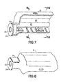
- a chamber 22 is of surrounded by the structure of the holder 5 and in general evenly formed in shape to the tank 7 record whatever the needs of the Tank environment.
- a generally cylindrical flange or nozzle 6 extends outward from the holder 5, around a structural seat 24 for the first coupling part 8 to build.
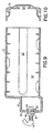
- the first coupling part 8 is shown in FIG. 9 as a so-called mother piece trained and takes the second Coupling part 9 of the tank 7 when the tank 7 in the chamber 22 is used.
- a T-shaped and like a Slit formed second form-locking part 23 is in the Holder 5 cast or embossed and opens to the Chamber 22 out with the correspondingly T-shaped first Positive locking part 16 of the tank 7 in a positive connection to be able to get there.
- the means by which the tank 7 in the Chamber 22 of the holder 5 engaged and secured can vary in appearance but it is important that the tank 7 can be set in a way that the Liquid connection of the tank 7 within the Fuel system 3 maintained. That kind of connection a second form-locking part 23 with a first Form-locking part 16 provides an effective fixing of the tank 7 in the holder 5.
- the engagement of the second clutch part 9th in the first coupling part 8 also ensures a Holding force.
- the first coupling part 8 is in an opening 25 mounted, which is formed in the seat 24 of the nozzle 6, and by means of a nut 26 which engages in the thread 20, securely attached in place.
- the engine 1 is by means of the distributor 13 to the Fuel system 3 connected as best in the Figures 2 and 3 is shown.
- the distributor 13 is in the essentially a steel pipe and surrounds an enlarged one Storage area 27 and a ventilation area 28, the are interconnected.
- the distributor 13 serves different purposes.
- the distributor 13 ensures a Vent the fuel system 3 at its highest open End. It contains one at its lower end first connection 29, which with the fuel line 11 in Connected, which leads to the inlet of the carburetor 12 to Feed fuel from the tank 7 to the carburetor 12.
- In one intermediate area is a third port 30 or Inflow area provided, which with the tank outlet 14 of the tank 7th communicates to the flow of fuel through the Allow storage area 27.
- An upper or second Connection 31 is in connection with a cleaning or Starter circuit that pumps fuel to the carburetor 12 allowed.
- the fuel is the distributor 13 due to the Gravity flows, and it is therefore necessary that the Manifold 13 and tank 7 are properly aligned to the Ensure the function of the fuel system 3.
- the Storage area 27 remains filled with fuel to sort Liquid seal for the fuel line 11 to the To produce carburetor 12. In this way, air bubbles prevented, which could lead to the performance of the Motors 1 drops, or it even switches off.
- the chamber 22 is designed to hold the tank 7 records, which has a general shape so that it with Motors 1 different models and different shapes can be used.
- the tank 7 forms a tight unit, when it is assembled with the second coupling part 9.
- the tank 7 is either through the second coupling part 9 or filled with fuel in another useful way.
- the Fuel is optimized for the engine in question by premixed oil, or other additives that are added improve exhaust emissions and increase engine performance.
- the tank 7 is attached to the holder 5 and on the fuel system 3 by snapping the first Coupling part 8 connected in the second coupling part 9, which conveniently connects and disconnects the tank 7 to or from the fuel system 3.
- the Complexity and the cost of the tank 7 are due to the Use of the distributor 13 minimized that Fuel system 3 vented and connected to the Manufactures fuel line 11 to the carburetor 12.
- the Distributor 13 also connects the fuel line 10 for the cleaning or starting circuit to the fuel system 3 ago.
- the storage area 27 is of a small size enlarged area of the passage of the distributor 13 is formed, that holds back a small amount of fuel. To this A constant sealing of the fuel line 11 is achieved created.
- a suitable fuel system 3 for Provided a sealed disposable tank 7 contains, which can be used without filling and mixing.
- the fuel itself can in terms of exhaust gases and Motor 1 performance can be optimized.
- By taking the tank 7 out is made from a recyclable material Environmental impact of the fuel system with reduced emissions of the engine 1 kept low.
Landscapes
- Engineering & Computer Science (AREA)
- Mechanical Engineering (AREA)
- General Engineering & Computer Science (AREA)
- Chemical & Material Sciences (AREA)
- Combustion & Propulsion (AREA)
- Cooling, Air Intake And Gas Exhaust, And Fuel Tank Arrangements In Propulsion Units (AREA)
Description
- Fig. 1
- einen Motor mit einem erfindungsgemäßen Kraftstoffsystem in perspektivischer Darstellung,
- Fig. 2
- einen Verteiler des Kraftstoffsystems aus Figur 1 in Seitenansicht,
- Fig. 3
- den Verteiler aus Figur 2 in einem vertikalen Längsschnitt,
- Fig. 4
- einen Tank des Kraftstoffsystems aus Figur 1 in perspektivischer Darstellung,
- Fig. 5
- den Tank aus Figur 4 in einem vertikalen Längsschnitt entlang der Linie 5-5 und in der Blickrichtung der dazugehörigen Pfeile in Figur 4,
- Fig. 6
- den Tank aus Figur 4 in einem vertikalen Querschnitt entlang der Linie 6-6 und in der Blickrichtung der dazugehörigen Pfeile in Figur 5,
- Fig. 7
- einen Halter des Kraftstoffsystems aus Figur 1 in perspektivischer Darstellung von einer Seite,
- Fig. 8
- den Halter aus Figur 7 in perspektivischer Darstellung von der anderen Seite,
- Fig. 9
- den Halter aus Figur 7 in einem vertikalen Längsschnitt entlang der Linie 9-9 und in der Blickrichtung der dazugehörigen Pfeile in Figur 7, und
- Fig. 10
- den Halter aus Figur 7 in einem vertikalen Querschnitt entlang der Linie 10-10 und in der Blickrichtung der dazugehörigen Pfeile in Figur 7.
Claims (12)
- Kraftstoffsystem (3) eines Verbrennungsmotors (1) mit einer Kraftstoffleitung (11) zur Abfuhr von Kraftstoff für Verbrennungszwecke und einem Tank (7), der mittels eines Halters (5) mittelbar oder unmittelbar an dem Verbrennungsmotor (1) befestigbar ist, wobei die Kraftstoffleitung (11) mit einem ersten Kupplungsteil (8) verbunden ist und der Tank (7) einen zweiten Kupplungsteil (9) aufweist, die dichtend miteinander verbindbar sind, und der Tank (7) mit einem ersten Formschlußteil (16) und der Halter (5) mit einem zweiten Formschlußteil (23) versehen ist, die lösbar miteinander in Verbindung bringbar sind, dadurch gekennzeichnet, daß ein Formschlußteil (16) in der Art eines hinausragenden Formflansches und der andere Formschlußteil (23) in der Art eines Schlitzes mit einem T-förmigen Querschnitt ausgebildet ist, der dem Querschnitt des Formflansches (16) im wesentlichen entspricht.
- Kraftstoffsystem nach Anspruch 1, dadurch gekennzeichnet, dass der Formflansch des ersten Formschlußteils (16) von dem Tank (7) hinausragt und der Schlitz in dem Halter (5) vorgesehen ist.
- Kraftstoffsystem nach Anspruch 1 oder 2, dadurch gekennzeichnet, daß der erste und/oder der zweite Kupplungsteil (8, 9) ein Sperrventil aufweisen.
- Kraftstoffsystem nach einem oder mehreren der vorherigen Ansprüche, dadurch gekennzeichnet, daß der Halter (5) mit einem Stutzen (6) versehen ist, in dem der erste Kupplungsteil (8) gehalten wird.
- Kraftstoffsystem nach einem oder mehreren der vorherigen Ansprüche, dadurch gekennzeichnet, daß der Tank (7) mit gebrauchsfertig gemischtem Kraftstoff gefüllt ist.
- Kraftstoffsystem nach einem oder mehreren der vorherigen Ansprüche, dadurch gekennzeichnet, daß der Tank (7) aus einem wiederverwertbaren Material besteht.
- Kraftstoffsystem nach einem oder mehreren der vorherigen Ansprüche, gekennzeichnet durch einen Verteiler (13) mit einem ersten Anschluß (29) für eine Kraftstoffleitung (11) zur Abgabe von Kraftstoff für den Verbrennungsvorgang, einem zweiten Anschluß (31) für eine Kraftstoffleitung (10) für eine Entlüftungs- und/oder Anlaßvorrichtung und einen dritten Anschluß (30) für die Verbindung mit dem Tank (7).
- Kraftstoffsystem nach Anspruch 7, dadurch gekennzeichnet, daß zwischen dem ersten und dem dritten Anschluß (29) und (30) ein Vorratsbereich (27) mit einem größeren Durchmesser vorgesehen ist.
- Kraftstoffsystem nach einem der Ansprüche 7 und 8, dadurch gekennzeichnet, daß der erste Anschluß (29) unterhalb des dritten Anschlusses (30) angeordnet ist.
- Kraftstoffsystem nach einem oder mehreren der Ansprüche 7 bis 9, dadurch gekennzeichnet, daß eine von dem Tank (7) getrennte Entlüftungsvorrichtung, insbesondere in dem Verteiler (13), vorgesehen ist.
- Kraftstoffsystem nach einem oder mehreren der Ansprüche 7 bis 10, dadurch gekennzeichnet, daß der durch den dritten Anschluß (30) ankommende Volumenstrom größer ist als der durch den ersten Anschluß (29) abfließende.
- Verwendung eines Kraftstoffsystems nach einem oder mehreren der Ansprüche 7 bis 11 für einen Verbrennungsmotor an Geräten der Grundstücks- und Gartenpflege, insbesondere Fadenmähern.
Applications Claiming Priority (2)
| Application Number | Priority Date | Filing Date | Title |
|---|---|---|---|
| US940210 | 1997-09-30 | ||
| US08/940,210 US5913296A (en) | 1997-09-30 | 1997-09-30 | Disposable modular fuel container for internal combustion engines |
Publications (2)
| Publication Number | Publication Date |
|---|---|
| EP0905373A1 EP0905373A1 (de) | 1999-03-31 |
| EP0905373B1 true EP0905373B1 (de) | 2002-12-04 |
Family
ID=25474424
Family Applications (1)
| Application Number | Title | Priority Date | Filing Date |
|---|---|---|---|
| EP98116785A Expired - Lifetime EP0905373B1 (de) | 1997-09-30 | 1998-09-05 | Kraftstoffsystem |
Country Status (4)
| Country | Link |
|---|---|
| US (1) | US5913296A (de) |
| EP (1) | EP0905373B1 (de) |
| JP (1) | JP3182400B2 (de) |
| DE (1) | DE59806509D1 (de) |
Families Citing this family (4)
| Publication number | Priority date | Publication date | Assignee | Title |
|---|---|---|---|---|
| CN1745015A (zh) * | 2002-11-30 | 2006-03-08 | 挪威船级社 | 船结构和船舶中的结构 |
| US20060117650A1 (en) * | 2004-12-03 | 2006-06-08 | Electrolux Home Products, Inc. | Single use two-cycle oil packets and method therefor |
| US20080184952A1 (en) * | 2005-06-08 | 2008-08-07 | Consumer Ready Products, Llc | Composition for powering engine |
| DE202010004275U1 (de) * | 2009-10-13 | 2011-02-24 | Makita Corp., Anjo | Einrichtung zur Kraftstoffzuleitung für einen Motor |
Family Cites Families (18)
| Publication number | Priority date | Publication date | Assignee | Title |
|---|---|---|---|---|
| US1691509A (en) * | 1927-04-07 | 1928-11-13 | Lister & Co Ltd R A | Tank for inflammable liquids |
| US1718603A (en) * | 1928-01-18 | 1929-06-25 | Arthur E Smith | Ampul |
| US2501470A (en) * | 1946-01-12 | 1950-03-21 | West Bend Aluminum Co | Outboard motor tank, engine, and support assembly |
| US2961014A (en) * | 1959-02-09 | 1960-11-22 | Joe S Appleton | Portable fuel supply |
| US3580423A (en) * | 1969-02-27 | 1971-05-25 | Realistic Co | Container closure and apparatus for opening same |
| US3613955A (en) * | 1969-07-15 | 1971-10-19 | Monsanto Co | Compartmentalized container package |
| US3731846A (en) * | 1971-07-16 | 1973-05-08 | W Turner | Fuel supply system for internal combustion engine powered portable tools and the like |
| DE2606185A1 (de) * | 1976-02-17 | 1977-08-18 | Farymann Diesel | Einrichtung zur brennstoffzufuhr von einem brennstoffbehaelter zu dem saugraum einer tiefer als der brennstoffbehaelter liegenden einspritzpumpe einer brennkraftmaschine |
| SE398627B (sv) * | 1976-04-28 | 1978-01-09 | Volvo Penta Ab | Anordning vid utombordsmotorer |
| US4445550B1 (en) * | 1982-08-20 | 1999-03-09 | Scholle Corp | Flexible walled container having membrane fitment for use with aseptic filling apparatus |
| EP0114585A3 (de) * | 1983-01-24 | 1985-01-09 | TEBALDI S.r.l. | Tragbarer Kraftstofftank für Aussenbordmotoren |
| IT1185850B (it) * | 1985-08-02 | 1987-11-18 | Zambon Spa | Tappo serbatoio contagocce per flaconi |
| US4648532A (en) * | 1986-05-09 | 1987-03-10 | Green Russell D | Mixing and discharge capsule |
| FR2618490A1 (fr) * | 1987-07-22 | 1989-01-27 | Rivapompe Sa | Dispositif de filtrage et de degazage d'un carburant d'alimentation pour moteur a combustion interne |
| US4901890A (en) * | 1988-06-24 | 1990-02-20 | Mivelaz Michael B | Watering system automatic additive dispenser kit |
| JPH0727378Y2 (ja) * | 1988-10-05 | 1995-06-21 | 株式会社共立 | 内燃機関 |
| US5701855A (en) * | 1996-10-04 | 1997-12-30 | Ryobi Limited | Cartridge fuel internal combustion engine |
| JPH10131809A (ja) * | 1996-10-30 | 1998-05-19 | Honda Motor Co Ltd | ガスエンジン及びガスエンジン作業機 |
-
1997
- 1997-09-30 US US08/940,210 patent/US5913296A/en not_active Expired - Fee Related
-
1998
- 1998-09-05 EP EP98116785A patent/EP0905373B1/de not_active Expired - Lifetime
- 1998-09-05 DE DE59806509T patent/DE59806509D1/de not_active Expired - Fee Related
- 1998-09-17 JP JP26275898A patent/JP3182400B2/ja not_active Expired - Fee Related
Also Published As
| Publication number | Publication date |
|---|---|
| JPH11159337A (ja) | 1999-06-15 |
| US5913296A (en) | 1999-06-22 |
| EP0905373A1 (de) | 1999-03-31 |
| JP3182400B2 (ja) | 2001-07-03 |
| DE59806509D1 (de) | 2003-01-16 |
Similar Documents
| Publication | Publication Date | Title |
|---|---|---|
| DE60224408T2 (de) | Fluidinjektor mit lüftungs-/proportionieröffnungen | |
| DE3320941A1 (de) | Brennkraftmaschine | |
| DE69316943T2 (de) | Tragbarer Bezinbehälter | |
| EP0812387B1 (de) | Einrichtung zum fördern von kraftstoff aus einem vorratstopf zur brennkraftmaschine eines kraftfahrzeuges | |
| DE19604288C1 (de) | Handgeführtes, tragbares Arbeitsgerät mit einem Verbrennungsmotor | |
| DE3827572A1 (de) | Vorrichtung zum foerdern von kraftstoff aus einem vorratstank zur brennkraftmaschine eines kraftfahrzeuges | |
| DE2736153A1 (de) | Filter- und mischeinrichtung zur vermischung von schmieroel und kraftstoff | |
| DE10259805A1 (de) | Bordeigene Vorrichtung zur Kraftstoffversorgung für ein Kraftfahrzeug | |
| DE4025225A1 (de) | Vergaser-oelpumpen-anordnung und verfahren fuer deren herstellung | |
| DE29812679U1 (de) | Druckausgleichssystem für einen Kraftstofftank eines Verbrennungsmotors, insbesondere für handgeführte, tragbare Arbeitsgeräte | |
| EP0905373A1 (de) | Kraftstoffsystem | |
| DE102008058498B4 (de) | Kraftstoffsystem eines handgeführten Arbeitsgerätes | |
| DE68910604T2 (de) | Kraftstoffversorgungsvorrichtung eines Motors. | |
| DE3815523C1 (de) | ||
| DE102004002654A1 (de) | Vorrichtung zur Füllstandsregulierung von Mehrkomponentenmaterialien | |
| DE4008609C1 (de) | ||
| DE29722869U1 (de) | Membranvergaser für ein tragbares, handgeführtes Arbeitsgerät | |
| DE1526691A1 (de) | Automatik-Vorrichtung fuer Vergaser | |
| EP3586625B1 (de) | Landwirtschaftliche feldspritze | |
| DE829257C (de) | Kreiselpumpe zum Aufruehren und Foerdern von Dickstoffen (Jauche, Schlamm usw.) aus Gruben | |
| DE2659067C3 (de) | Kreiskolben-Brennkraftmaschine | |
| DE958439C (de) | Zusatzvorrichtung fuer Vergaser fuer Verbrennungsmotore | |
| DE10316804A1 (de) | Kraftstoffabsaugeinrichtung für einen Vergaser | |
| DD298148A5 (de) | Vorrichtung in einer kraftstoffanlage fuer einen verbrennungsmotor | |
| DE10109207A1 (de) | Verbindungsstutzen zwischen einem Vergaser und einem Zylinder eines Verbrennungsmotors |
Legal Events
| Date | Code | Title | Description |
|---|---|---|---|
| PUAI | Public reference made under article 153(3) epc to a published international application that has entered the european phase |
Free format text: ORIGINAL CODE: 0009012 |
|
| AK | Designated contracting states |
Kind code of ref document: A1 Designated state(s): DE FR GB IT |
|
| AX | Request for extension of the european patent |
Free format text: AL;LT;LV;MK;RO;SI |
|
| 17P | Request for examination filed |
Effective date: 19990918 |
|
| AKX | Designation fees paid |
Free format text: DE FR GB IT |
|
| 17Q | First examination report despatched |
Effective date: 20010424 |
|
| GRAG | Despatch of communication of intention to grant |
Free format text: ORIGINAL CODE: EPIDOS AGRA |
|
| RAP1 | Party data changed (applicant data changed or rights of an application transferred) |
Owner name: TECHTRONIC INDUSTRIES CO., LTD. |
|
| GRAG | Despatch of communication of intention to grant |
Free format text: ORIGINAL CODE: EPIDOS AGRA |
|
| GRAH | Despatch of communication of intention to grant a patent |
Free format text: ORIGINAL CODE: EPIDOS IGRA |
|
| GRAH | Despatch of communication of intention to grant a patent |
Free format text: ORIGINAL CODE: EPIDOS IGRA |
|
| GRAA | (expected) grant |
Free format text: ORIGINAL CODE: 0009210 |
|
| AK | Designated contracting states |
Kind code of ref document: B1 Designated state(s): DE FR GB IT |
|
| REG | Reference to a national code |
Ref country code: GB Ref legal event code: FG4D Free format text: NOT ENGLISH |
|
| GBT | Gb: translation of ep patent filed (gb section 77(6)(a)/1977) |
Effective date: 20021204 |
|
| REF | Corresponds to: |
Ref document number: 59806509 Country of ref document: DE Date of ref document: 20030116 |
|
| ET | Fr: translation filed | ||
| PLBE | No opposition filed within time limit |
Free format text: ORIGINAL CODE: 0009261 |
|
| STAA | Information on the status of an ep patent application or granted ep patent |
Free format text: STATUS: NO OPPOSITION FILED WITHIN TIME LIMIT |
|
| 26N | No opposition filed |
Effective date: 20030905 |
|
| PGFP | Annual fee paid to national office [announced via postgrant information from national office to epo] |
Ref country code: IT Payment date: 20080925 Year of fee payment: 11 Ref country code: FR Payment date: 20080917 Year of fee payment: 11 |
|
| PGFP | Annual fee paid to national office [announced via postgrant information from national office to epo] |
Ref country code: GB Payment date: 20080922 Year of fee payment: 11 |
|
| PGFP | Annual fee paid to national office [announced via postgrant information from national office to epo] |
Ref country code: DE Payment date: 20081125 Year of fee payment: 11 |
|
| GBPC | Gb: european patent ceased through non-payment of renewal fee |
Effective date: 20090905 |
|
| REG | Reference to a national code |
Ref country code: FR Ref legal event code: ST Effective date: 20100531 |
|
| PG25 | Lapsed in a contracting state [announced via postgrant information from national office to epo] |
Ref country code: FR Free format text: LAPSE BECAUSE OF NON-PAYMENT OF DUE FEES Effective date: 20090930 Ref country code: DE Free format text: LAPSE BECAUSE OF NON-PAYMENT OF DUE FEES Effective date: 20100401 |
|
| PG25 | Lapsed in a contracting state [announced via postgrant information from national office to epo] |
Ref country code: GB Free format text: LAPSE BECAUSE OF NON-PAYMENT OF DUE FEES Effective date: 20090905 |
|
| PG25 | Lapsed in a contracting state [announced via postgrant information from national office to epo] |
Ref country code: IT Free format text: LAPSE BECAUSE OF NON-PAYMENT OF DUE FEES Effective date: 20090905 |