EP0905009A2 - Kotflügel für Fahrzeuge , insbesondere für eine Zugmaschine für Anhänger - Google Patents
Kotflügel für Fahrzeuge , insbesondere für eine Zugmaschine für Anhänger Download PDFInfo
- Publication number
- EP0905009A2 EP0905009A2 EP98610036A EP98610036A EP0905009A2 EP 0905009 A2 EP0905009 A2 EP 0905009A2 EP 98610036 A EP98610036 A EP 98610036A EP 98610036 A EP98610036 A EP 98610036A EP 0905009 A2 EP0905009 A2 EP 0905009A2
- Authority
- EP
- European Patent Office
- Prior art keywords
- guard
- recesses
- holder
- clamp
- slot
- Prior art date
- Legal status (The legal status is an assumption and is not a legal conclusion. Google has not performed a legal analysis and makes no representation as to the accuracy of the status listed.)
- Granted
Links
- 239000002184 metal Substances 0.000 claims description 4
- 229910001220 stainless steel Inorganic materials 0.000 claims 1
- 239000010935 stainless steel Substances 0.000 claims 1
- 239000000725 suspension Substances 0.000 description 5
- 238000000034 method Methods 0.000 description 4
- 210000002105 tongue Anatomy 0.000 description 4
- RTZKZFJDLAIYFH-UHFFFAOYSA-N Diethyl ether Chemical compound CCOCC RTZKZFJDLAIYFH-UHFFFAOYSA-N 0.000 description 2
- 239000000853 adhesive Substances 0.000 description 1
- 230000001070 adhesive effect Effects 0.000 description 1
- 230000000712 assembly Effects 0.000 description 1
- 238000000429 assembly Methods 0.000 description 1
- 238000010276 construction Methods 0.000 description 1
- 230000001419 dependent effect Effects 0.000 description 1
- 230000000694 effects Effects 0.000 description 1
- 239000007787 solid Substances 0.000 description 1
- 238000005507 spraying Methods 0.000 description 1
- XLYOFNOQVPJJNP-UHFFFAOYSA-N water Substances O XLYOFNOQVPJJNP-UHFFFAOYSA-N 0.000 description 1
Images

Classifications
-
- B—PERFORMING OPERATIONS; TRANSPORTING
- B62—LAND VEHICLES FOR TRAVELLING OTHERWISE THAN ON RAILS
- B62D—MOTOR VEHICLES; TRAILERS
- B62D25/00—Superstructure or monocoque structure sub-units; Parts or details thereof not otherwise provided for
- B62D25/08—Front or rear portions
- B62D25/16—Mud-guards or wings; Wheel cover panels
- B62D25/168—Mud guards for utility vehicles
Definitions
- the present invention concerns a mudguard for a wheeled vehicle, especially a rear guard for a tractor or motor forecarriage for the pulling of a trailer, said guard being configured in such a manner that two guard holders, which extend from the side of the chassis frame of the tractor or motor forecarrige, can be received in selectable positions on the outer side of the guard.
- Two guard holders in the form of tubes or other forms of profiles which are ether straight or bent in fashion are mounted on the side of the chassis frame of a tractor and extend laterally out to the side.
- the guard is mounted on the guard holders by means of various brackets.
- the guard holders retain the guards in a pre-determined position so that the relevant legislative demands are met, for example conceming water-splash from the wheels.
- the guard type and/or the vertical position of the guard must be changed, which makes it necessary to change the position of the guard holders, or use must be made of another guard holder of a configuration which allows for the changed positioning and shape of the guard.
- guard holders and/or guards of different configurations for each combination of tyre dimension and/or suspension type. This involves guard holders and guards of many variants and herewith related logistical, design and construction costs.
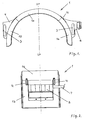
- the special characteristic of the guard according to the invention is that the guard has a first and a corresponding second guard holder part on opposing sides of a vertical symmetrical plane, which in the guard's position of use extends through the axis of a wheel which is to be guarded, that the guard holder parts each have a series of recesses which are arranged in a straight line parallel with the symmetrical plane, and that the recesses are configured to receive a guard holder arranged to suit the guard holder parts both parallel with the symmetrical plane (SP) and lengthwise with the guard holders.
- SP symmetrical plane
- the guard can easily be brought to an optimum horizontal height above the periphery of the wheel which is to be guarded, and the guard with guard holder parts can thereafter be displaced along the guard holders to a correct position at the side in relation to the wheel.
- the guard 1 is preferably made of plastic, and is configured in a known manner with a centre part 1a and two identical end parts 1b.
- the designation SP indicates the symmetrical plane which, in the guard's 1 position of use, extends vertically through the axis of a wheel which is to be guarded, so that the spraying of water from the wheel is limited.
- the centre part 1a is provided along the end edges with a slot 1d which can receive a protruding tongue 1e on the end parts 1b, said slots 1d and tongues 1e being staggered in such a manner that the surfaces of the centre part 1a and the end parts 1b are flush after the assembly.
- the end parts 1b are held in a fixed manner on the centre part 1a, for example by an adhesive'between the slots 1d and the tongues 1e, but the parts can also be separable by means of fishplates 1c which are screwed on the parts and extend across the assemblies as shown in fig. 2.
- Both of the end parts 1b are provided with guard holder parts 2 which are identical, but one of these guard holder parts 2 is designed for mounting on the foremost end part 1b of the guard 1 after having been provided with a casing 4, while the other guard holder part 2 is designed for mounting on that part of the guard 1 which faces rearwards to the driving direction after having been provided with a lamp housing 8.
- the guard holder parts 2 are made of plastic and are secured to the end parts 1b in a suitable manner, or are produced in one piece with the end parts 1b.
- each guard holder part 2 there are provided a series of recesses 5, each of which is in the form of a semi-circle with the same radius as the guard holder 7.
- the recesses 5 are arranged along a straight line and, in the guard's position of use, extend parallel with the symmetrical plane SP and are therefore vertical in the guard's position of use.
- the guard 1 When the guard holders 7 are mounted in a given position on the chassis frame of the tractor, the guard 1 can thus be moved up or down in relation to the wheel which is to be guarded.
- the recesses 5 are preferably configured from a strip of metal which is bent in the desired shape and is secured in the guard holder parts 2, for example by means of screws or similar securing means, as shown in fig. 3.
- the recesses 5 can also consist of plastic and be produced in one piece with a guard holder part.
- a clamp 6 which can be tightened over a guard holder 7 which has been selected to be received in one of the recesses 5, so that the guard 1 can be adjusted to the correct height in relation to a wheel.
- the clamp 6 is substantially semi-circular with the same radius as the guard holders 7.
- the clamp 6 has a lug which extends as a tangent to the semi-circle, and which has cut-outs on the sides in such a manner that when the plane of the lug is flush with the slot, the lug on the clamp 6 can be inserted in a narrow slot in the strip with the recesses 5, and can thereafter, after having been turned 90° in relation to the slot, with its cut-outs be engaged firmly with the sides of the slot.
- the clamp 6 has a tongue which extends more or less at right-angles to the lug and is provided with a hole for a screw, whereby the clamp 6 can be fastened firmly in relation to a given recess 5.
- a casing 4 which can cover the guard holder part 2, and a lamp housing 8 is mounted rearmost on the other guard holder part 2; said lamp housing is shown in fig. 3 and is otherwise of a commonly-known kind.
- the casing 4 and the lamp housing 8 are configured to enclose each their guard holder part 2, and each has a slot 3 which extends parallel with the recesses 5.
- the slots 3 have a breadth which is determined in accordance with the dimensions of the guard holders 7, which extend laterally out to the sides from the chassis frame of the tractor, said guard holders 7 being positioned at more or less the same horizontal height and with a predetermined mutual distance in the horizontal plane.
- the guard according to the invention is easy to mount without any troublesome measuring of the mounting holes for the guard holders, that it is easy to adjust to an optimum position in relation to the wheel to be guarded, and that the securing of the guard is solid and can withstand influences which can arise during the use of a truck.
Landscapes
- Engineering & Computer Science (AREA)
- Chemical & Material Sciences (AREA)
- Combustion & Propulsion (AREA)
- Transportation (AREA)
- Mechanical Engineering (AREA)
- Body Structure For Vehicles (AREA)
- Lighting Device Outwards From Vehicle And Optical Signal (AREA)
Applications Claiming Priority (2)
| Application Number | Priority Date | Filing Date | Title |
|---|---|---|---|
| DK106997 | 1997-09-18 | ||
| DK106997 | 1997-09-18 |
Publications (3)
| Publication Number | Publication Date |
|---|---|
| EP0905009A2 true EP0905009A2 (de) | 1999-03-31 |
| EP0905009A3 EP0905009A3 (de) | 2001-02-28 |
| EP0905009B1 EP0905009B1 (de) | 2003-08-27 |
Family
ID=8100644
Family Applications (1)
| Application Number | Title | Priority Date | Filing Date |
|---|---|---|---|
| EP19980610036 Expired - Lifetime EP0905009B1 (de) | 1997-09-18 | 1998-09-14 | Kotflügel für Fahrzeuge , insbesondere für eine Zugmaschine für Anhänger |
Country Status (1)
| Country | Link |
|---|---|
| EP (1) | EP0905009B1 (de) |
Cited By (2)
| Publication number | Priority date | Publication date | Assignee | Title |
|---|---|---|---|---|
| WO2012076198A1 (en) * | 2010-12-09 | 2012-06-14 | Agco International Gmbh | Wheel fender support |
| WO2017204715A1 (en) * | 2016-05-26 | 2017-11-30 | Scania Cv Ab | An attachment assembly for mounting a mudguard and a mudguard assembly |
Families Citing this family (2)
| Publication number | Priority date | Publication date | Assignee | Title |
|---|---|---|---|---|
| DE102006032289B4 (de) * | 2006-07-11 | 2013-07-11 | Wegu Gmbh & Co. Kg | Kotflügel für einen Lastkraftwagen oder Lastkraftwagenanhänger |
| DE102017105528B3 (de) | 2017-03-15 | 2018-09-06 | Wegu Gmbh Leichtbausysteme | LKW-Kotflügel |
Family Cites Families (3)
| Publication number | Priority date | Publication date | Assignee | Title |
|---|---|---|---|---|
| FR2556301B1 (fr) * | 1983-12-07 | 1989-04-28 | Fichet Jacques | Garde-boue de vehicule routier |
| DE8609090U1 (de) * | 1986-04-04 | 1987-07-30 | BÄWA Bätzold & Wagner GmbH & Co KG, 5608 Radevormwald | Haltevorrichtung für Kotflügel an Lastkraftwagen |
| DE9401381U1 (de) * | 1994-01-27 | 1994-04-07 | Köver GmbH & Co. KG Metall- und Kunststoffverarbeitung, 21614 Buxtehude | Kotflügelhalter |
-
1998
- 1998-09-14 EP EP19980610036 patent/EP0905009B1/de not_active Expired - Lifetime
Non-Patent Citations (1)
| Title |
|---|
| None |
Cited By (5)
| Publication number | Priority date | Publication date | Assignee | Title |
|---|---|---|---|---|
| WO2012076198A1 (en) * | 2010-12-09 | 2012-06-14 | Agco International Gmbh | Wheel fender support |
| WO2017204715A1 (en) * | 2016-05-26 | 2017-11-30 | Scania Cv Ab | An attachment assembly for mounting a mudguard and a mudguard assembly |
| KR20180134414A (ko) * | 2016-05-26 | 2018-12-18 | 스카니아 씨브이 악티에볼라그 | 머드가드를 장착하기 위한 부착 어셈블리 및 머드가드 어셈블리 |
| CN109153414A (zh) * | 2016-05-26 | 2019-01-04 | 斯堪尼亚商用车有限公司 | 用于安装挡泥件的附接组件和挡泥件组件 |
| CN109153414B (zh) * | 2016-05-26 | 2021-03-19 | 斯堪尼亚商用车有限公司 | 用于安装挡泥件的附接组件和挡泥件组件 |
Also Published As
| Publication number | Publication date |
|---|---|
| EP0905009A3 (de) | 2001-02-28 |
| EP0905009B1 (de) | 2003-08-27 |
Similar Documents
| Publication | Publication Date | Title |
|---|---|---|
| EP0223472B1 (de) | Spritzschutz | |
| EP1982901B1 (de) | Kotflügel mit einstellbarer Halterung | |
| US4671552A (en) | Grill guard for vehicle front end | |
| CA1283145C (en) | Vehicle quarter fender | |
| US5882054A (en) | Device for precise positioning of a vehicle body part relative to another body part | |
| US12122455B2 (en) | Vehicle protection system to secure a protective covering to an axle of a vehicle | |
| US6588781B2 (en) | Vehicle side step assembly | |
| US6431605B1 (en) | Conspicuity plate assembly for fender mounting | |
| EP3464032B1 (de) | Befestigungsanordnung zur montage eines kotflügels und kotflügelanordnung | |
| US4706980A (en) | Vehicle quarter fender and assembly for mounting the same | |
| US5630653A (en) | Wheel cover mounting bracket | |
| US20200070895A1 (en) | Vehicle front-end assembly | |
| US6357707B1 (en) | Mounting clamp | |
| JP4909183B2 (ja) | 走行車両のフェンダ装置 | |
| EP0905009B1 (de) | Kotflügel für Fahrzeuge , insbesondere für eine Zugmaschine für Anhänger | |
| US11214107B2 (en) | Vehicle front-end assembly | |
| US11167608B2 (en) | Vehicle front-end assembly | |
| CA3150455C (en) | Bumper with selectively attachable light bars | |
| US5335155A (en) | Tail light construction | |
| FR2813847B1 (fr) | Systeme de montage d'un garde-boue equipant une roue directrice d'un vehicule | |
| EP1186442A2 (de) | Rad für Spurbreitenveränderung mit Zentriervorrichtung mittels Dübeln | |
| CN215706822U (zh) | 一种前轮挡泥板及电动车 | |
| JP4055832B2 (ja) | スペアタイヤホルダー | |
| US6007144A (en) | Gap covering member for different types of pickup trucks | |
| CN214823649U (zh) | 一种防飞溅的车轮挡泥板组件 |
Legal Events
| Date | Code | Title | Description |
|---|---|---|---|
| PUAI | Public reference made under article 153(3) epc to a published international application that has entered the european phase |
Free format text: ORIGINAL CODE: 0009012 |
|
| AK | Designated contracting states |
Kind code of ref document: A2 Designated state(s): BE ES FI FR GB IT NL SE |
|
| AX | Request for extension of the european patent |
Free format text: AL;LT;LV;MK;RO;SI |
|
| PUAL | Search report despatched |
Free format text: ORIGINAL CODE: 0009013 |
|
| AK | Designated contracting states |
Kind code of ref document: A3 Designated state(s): AT BE CH CY DE DK ES FI FR GB GR IE IT LI LU MC NL PT SE |
|
| AX | Request for extension of the european patent |
Free format text: AL;LT;LV;MK;RO;SI |
|
| 17P | Request for examination filed |
Effective date: 20010828 |
|
| AKX | Designation fees paid |
Free format text: BE ES FI FR GB IT NL SE |
|
| REG | Reference to a national code |
Ref country code: DE Ref legal event code: 8566 |
|
| GRAH | Despatch of communication of intention to grant a patent |
Free format text: ORIGINAL CODE: EPIDOS IGRA |
|
| GRAS | Grant fee paid |
Free format text: ORIGINAL CODE: EPIDOSNIGR3 |
|
| GRAA | (expected) grant |
Free format text: ORIGINAL CODE: 0009210 |
|
| AK | Designated contracting states |
Designated state(s): BE ES FI FR GB IT NL SE |
|
| PG25 | Lapsed in a contracting state [announced via postgrant information from national office to epo] |
Ref country code: NL Free format text: LAPSE BECAUSE OF FAILURE TO SUBMIT A TRANSLATION OF THE DESCRIPTION OR TO PAY THE FEE WITHIN THE PRESCRIBED TIME-LIMIT Effective date: 20030827 Ref country code: IT Free format text: LAPSE BECAUSE OF FAILURE TO SUBMIT A TRANSLATION OF THE DESCRIPTION OR TO PAY THE FEE WITHIN THE PRESCRIBED TIME-LIMIT;WARNING: LAPSES OF ITALIAN PATENTS WITH EFFECTIVE DATE BEFORE 2007 MAY HAVE OCCURRED AT ANY TIME BEFORE 2007. THE CORRECT EFFECTIVE DATE MAY BE DIFFERENT FROM THE ONE RECORDED. Effective date: 20030827 Ref country code: FR Free format text: LAPSE BECAUSE OF FAILURE TO SUBMIT A TRANSLATION OF THE DESCRIPTION OR TO PAY THE FEE WITHIN THE PRESCRIBED TIME-LIMIT Effective date: 20030827 Ref country code: FI Free format text: LAPSE BECAUSE OF FAILURE TO SUBMIT A TRANSLATION OF THE DESCRIPTION OR TO PAY THE FEE WITHIN THE PRESCRIBED TIME-LIMIT Effective date: 20030827 Ref country code: BE Free format text: LAPSE BECAUSE OF FAILURE TO SUBMIT A TRANSLATION OF THE DESCRIPTION OR TO PAY THE FEE WITHIN THE PRESCRIBED TIME-LIMIT Effective date: 20030827 |
|
| REG | Reference to a national code |
Ref country code: GB Ref legal event code: FG4D |
|
| PG25 | Lapsed in a contracting state [announced via postgrant information from national office to epo] |
Ref country code: SE Free format text: LAPSE BECAUSE OF FAILURE TO SUBMIT A TRANSLATION OF THE DESCRIPTION OR TO PAY THE FEE WITHIN THE PRESCRIBED TIME-LIMIT Effective date: 20031127 Ref country code: GB Free format text: LAPSE BECAUSE OF NON-PAYMENT OF DUE FEES Effective date: 20031127 |
|
| PG25 | Lapsed in a contracting state [announced via postgrant information from national office to epo] |
Ref country code: ES Free format text: LAPSE BECAUSE OF FAILURE TO SUBMIT A TRANSLATION OF THE DESCRIPTION OR TO PAY THE FEE WITHIN THE PRESCRIBED TIME-LIMIT Effective date: 20031208 |
|
| NLV1 | Nl: lapsed or annulled due to failure to fulfill the requirements of art. 29p and 29m of the patents act | ||
| PLBE | No opposition filed within time limit |
Free format text: ORIGINAL CODE: 0009261 |
|
| STAA | Information on the status of an ep patent application or granted ep patent |
Free format text: STATUS: NO OPPOSITION FILED WITHIN TIME LIMIT |
|
| GBPC | Gb: european patent ceased through non-payment of renewal fee |
Effective date: 20031127 |
|
| 26N | No opposition filed |
Effective date: 20040528 |
|
| EN | Fr: translation not filed |