EP0904983B1 - Wischer für den Spiegel eines Kraftfahrzeuges - Google Patents
Wischer für den Spiegel eines Kraftfahrzeuges Download PDFInfo
- Publication number
- EP0904983B1 EP0904983B1 EP98203215A EP98203215A EP0904983B1 EP 0904983 B1 EP0904983 B1 EP 0904983B1 EP 98203215 A EP98203215 A EP 98203215A EP 98203215 A EP98203215 A EP 98203215A EP 0904983 B1 EP0904983 B1 EP 0904983B1
- Authority
- EP
- European Patent Office
- Prior art keywords
- wiper
- mirror
- drive
- section
- casing
- Prior art date
- Legal status (The legal status is an assumption and is not a legal conclusion. Google has not performed a legal analysis and makes no representation as to the accuracy of the status listed.)
- Expired - Lifetime
Links
- 238000006073 displacement reaction Methods 0.000 description 5
- 230000008878 coupling Effects 0.000 description 3
- 238000010168 coupling process Methods 0.000 description 3
- 238000005859 coupling reaction Methods 0.000 description 3
- 238000003780 insertion Methods 0.000 description 3
- 230000037431 insertion Effects 0.000 description 3
- 125000006850 spacer group Chemical group 0.000 description 3
- 238000010586 diagram Methods 0.000 description 2
- 230000000694 effects Effects 0.000 description 2
- 230000002787 reinforcement Effects 0.000 description 2
- 238000001514 detection method Methods 0.000 description 1
- 230000006866 deterioration Effects 0.000 description 1
- 239000011521 glass Substances 0.000 description 1
- 238000000465 moulding Methods 0.000 description 1
- 238000012856 packing Methods 0.000 description 1
- 229920005989 resin Polymers 0.000 description 1
- 239000011347 resin Substances 0.000 description 1
- 238000004904 shortening Methods 0.000 description 1
- 229920003002 synthetic resin Polymers 0.000 description 1
- 239000000057 synthetic resin Substances 0.000 description 1
Images


Classifications
-
- B—PERFORMING OPERATIONS; TRANSPORTING
- B60—VEHICLES IN GENERAL
- B60S—SERVICING, CLEANING, REPAIRING, SUPPORTING, LIFTING, OR MANOEUVRING OF VEHICLES, NOT OTHERWISE PROVIDED FOR
- B60S1/00—Cleaning of vehicles
- B60S1/02—Cleaning windscreens, windows or optical devices
- B60S1/04—Wipers or the like, e.g. scrapers
- B60S1/06—Wipers or the like, e.g. scrapers characterised by the drive
- B60S1/16—Means for transmitting drive
- B60S1/18—Means for transmitting drive mechanically
-
- B—PERFORMING OPERATIONS; TRANSPORTING
- B60—VEHICLES IN GENERAL
- B60R—VEHICLES, VEHICLE FITTINGS, OR VEHICLE PARTS, NOT OTHERWISE PROVIDED FOR
- B60R1/00—Optical viewing arrangements; Real-time viewing arrangements for drivers or passengers using optical image capturing systems, e.g. cameras or video systems specially adapted for use in or on vehicles
- B60R1/02—Rear-view mirror arrangements
- B60R1/06—Rear-view mirror arrangements mounted on vehicle exterior
- B60R1/0602—Rear-view mirror arrangements mounted on vehicle exterior comprising means for cleaning or deicing
-
- B—PERFORMING OPERATIONS; TRANSPORTING
- B60—VEHICLES IN GENERAL
- B60R—VEHICLES, VEHICLE FITTINGS, OR VEHICLE PARTS, NOT OTHERWISE PROVIDED FOR
- B60R1/00—Optical viewing arrangements; Real-time viewing arrangements for drivers or passengers using optical image capturing systems, e.g. cameras or video systems specially adapted for use in or on vehicles
- B60R1/02—Rear-view mirror arrangements
- B60R1/06—Rear-view mirror arrangements mounted on vehicle exterior
- B60R1/0605—Rear-view mirror arrangements mounted on vehicle exterior specially adapted for mounting on trucks, e.g. by C-shaped support means
- B60R1/0607—Rear-view mirror arrangements mounted on vehicle exterior specially adapted for mounting on trucks, e.g. by C-shaped support means with remote position control adjustment
- B60R1/0612—Rear-view mirror arrangements mounted on vehicle exterior specially adapted for mounting on trucks, e.g. by C-shaped support means with remote position control adjustment by electrically actuated means
-
- B—PERFORMING OPERATIONS; TRANSPORTING
- B60—VEHICLES IN GENERAL
- B60R—VEHICLES, VEHICLE FITTINGS, OR VEHICLE PARTS, NOT OTHERWISE PROVIDED FOR
- B60R1/00—Optical viewing arrangements; Real-time viewing arrangements for drivers or passengers using optical image capturing systems, e.g. cameras or video systems specially adapted for use in or on vehicles
- B60R1/02—Rear-view mirror arrangements
- B60R1/06—Rear-view mirror arrangements mounted on vehicle exterior
- B60R1/062—Rear-view mirror arrangements mounted on vehicle exterior with remote control for adjusting position
- B60R1/07—Rear-view mirror arrangements mounted on vehicle exterior with remote control for adjusting position by electrically powered actuators
- B60R1/072—Rear-view mirror arrangements mounted on vehicle exterior with remote control for adjusting position by electrically powered actuators for adjusting the mirror relative to its housing
-
- B—PERFORMING OPERATIONS; TRANSPORTING
- B60—VEHICLES IN GENERAL
- B60S—SERVICING, CLEANING, REPAIRING, SUPPORTING, LIFTING, OR MANOEUVRING OF VEHICLES, NOT OTHERWISE PROVIDED FOR
- B60S1/00—Cleaning of vehicles
- B60S1/02—Cleaning windscreens, windows or optical devices
- B60S1/04—Wipers or the like, e.g. scrapers
- B60S1/06—Wipers or the like, e.g. scrapers characterised by the drive
- B60S1/16—Means for transmitting drive
- B60S1/166—Means for transmitting drive characterised by the combination of a motor-reduction unit and a mechanism for converting rotary into oscillatory movement
-
- B—PERFORMING OPERATIONS; TRANSPORTING
- B60—VEHICLES IN GENERAL
- B60S—SERVICING, CLEANING, REPAIRING, SUPPORTING, LIFTING, OR MANOEUVRING OF VEHICLES, NOT OTHERWISE PROVIDED FOR
- B60S1/00—Cleaning of vehicles
- B60S1/02—Cleaning windscreens, windows or optical devices
- B60S1/04—Wipers or the like, e.g. scrapers
- B60S1/32—Wipers or the like, e.g. scrapers characterised by constructional features of wiper blade arms or blades
- B60S1/34—Wiper arms; Mountings therefor
- B60S1/3418—Wiper arms; Mountings therefor with means for additionally adjusting the wiper arm working position with respect to the surface to be wiped
-
- B—PERFORMING OPERATIONS; TRANSPORTING
- B60—VEHICLES IN GENERAL
- B60S—SERVICING, CLEANING, REPAIRING, SUPPORTING, LIFTING, OR MANOEUVRING OF VEHICLES, NOT OTHERWISE PROVIDED FOR
- B60S1/00—Cleaning of vehicles
- B60S1/02—Cleaning windscreens, windows or optical devices
- B60S1/04—Wipers or the like, e.g. scrapers
- B60S1/32—Wipers or the like, e.g. scrapers characterised by constructional features of wiper blade arms or blades
- B60S1/34—Wiper arms; Mountings therefor
- B60S1/342—Wiper arms; Mountings therefor with means for temporarily uncoupling the wiper arm from the drive
Definitions
- the present invention relates to wipers that are used in vehicular mirrors which can be electrically tilted, such as a door mirror, a side-view mirror, etc. as described in the preamble of claim 1 and disclosed in document JP-A-07 304 426.
- some of the vehicular door mirrors and side-view mirrors are provided with a wiper which wipe waterdrops attached to the surface to ensure visibility.
- Fig. 14 shows a side-view mirror 1 provided with such a wiper function.
- the side-view mirror 1 is equipped with a mirror main body 10, a wiper main body 20, and a link mechanism section 30 connecting this wiper main body 20 with the mirror main body 10.
- the mirror main body 10 is equipped with a synthetic resin housing 11, a reinforcement plate 12 fixed to the housing 11, and a mirror drive unit 13 fixed to the reinforcement plate 12. Furthermore, the mirror main body 10 is equipped with a wiper drive unit 14 fixed to the housing 11, rods 15 fixed to the mirror drive unit 13, a mirror base 16 connected to the mirror drive unit 13 through the rods 15, a mirror 17 held by the mirror base 16, holding plates 18 fixed to the housing 11 and clamping a stay 2 fixed to a vehicular body (not shown), and a cover 19 for the holding plate 18.
- the wiper main body 20 is equipped with a wiper arm 21, a primary lever 22 connected to the free end of the wiper arm 21, secondary levers 23 connected to both ends of the primary lever 22 so that they are pivotable, a vertebra 24 held over the secondary levers 23, and a wiper blade 25 pivotably held on the vertebra 24.
- the link mechanism section 30 is equipped with a first link member 31 mounted at one end thereof on the output shaft 14a of the wiper drive unit 14, a second link member 32 coupled at one end thereof to the other end of the first link member 31 through a shaft 32, a third link member 35 coupled at one end thereof to the other end of the second link member 33 through a shaft 34, and a wiper shaft 40 coupled to the other end of the third link member 35.
- the third link member 35 is provided with a cylinder member 35a rotatably inserted into a cylindrical portion 11a protruding from the housing 11.
- the wiper shaft 40 is equipped with a pair of shaft members 41 and 42 and a coupling member 43.
- the coupling member 43 couples one end of the inner shaft member 41 and one end of the outer shaft member 42 together, thereby making the intermediate portion of the wiper shaft 40 bendable and allowing rotation of the wiper shaft 40.
- the other end of the inner shaft member 41 (one end of the wiper shaft 40) is held in the cylinder member 35a so that it cannot rotate relative to the cylinder member 35a and can slide along the axial direction of the cylinder member 35a. Therefore, the rotary motion of the output shaft 14a is converted to reciprocal rotary motion by the link members 31, 33, and 35, and this reciprocal rotary motion is transferred to the wiper shaft 40.
- the other end of the outer shaft member 42 (the other end of the wiper shaft 40) passes through holes formed in the mirror base 16 and mirror 17 and is fixed to the base portion 21a of the wiper arm 21 by means of a nut 26.
- the range of rotation of the wiper shaft 40 depends upon the setting of the link mechanism section 30.
- the coupled position of the wiper arm 21 relative to the wiper shaft 40 is adjusted according to the range of rotation of the wiper shaft 40. With this, the wiping range of the wiper blade 25 relative to the mirror 17 is determined.
- the wiping range is set so that it is slightly narrower than the reciprocal rotary motion range of the wiper main body 20 by protruding the housing 11 from the surface of the mirror 17. Therefore, if the wiper blade 25 abuts on the housing 11, the reciprocal rotary motion range will be consistent with the wiping range. At this time, even if the reciprocal rotary motion range of the wiper main body 20 is wider than the wiping range, the difference will be slight and therefore there will be no possibility that deformation of the wiper arm 21, damage to the wiper motor within the wiper drive unit 14, etc., will occur. In other words, the wiping range is set so that it is within an allowable range in which deformation of the wiper arm 21 and damage to the wiper motor will not occur.
- the mirror drive unit 13 and the wiper drive unit 14 are provided independently of each other. Moreover, the wiper drive unit 14 is provided at a position away from the mirror drive unit 13. For this . reason, the output shaft 14a of the wiper drive unit 14 and the shaft 32 are at positions away from the wiper shaft 40.
- the present invention has been made in view of the aforementioned disadvantages. Accordingly, it is an object of the present invention to provide a wiper assembly for a vehicular mirror which is capable of housing drive components in a single drive section casing and also shortening link members.
- a wiper assembly for a vehicular mirror which comprises: a mirror casing for holding a mirror; wiper drive means housed in a drive section casing; wiper drive transfer means housed in the drive section casing for transferring rotation of the wiper drive means; a link mechanism section housed in the mirror casing for converting the rotation transferred by the wiper drive transfer means to reciprocating motion; a rotary shaft section housed in the mirror casing for converting the reciprocating motion converted by the link mechanism section to reciprocal rotary motion; a wiper main body for wiping a surface of the mirror by the reciprocal rotary motion converted by the rotary shaft section; and a mirror tilting unit housed in the drive section casing for tilting the mirror.
- reference numeral 50 denotes a mirror main body.
- the circumferential edge and back surface of this mirror main body 50 is covered with a housing 51.
- a bracket 52 and a connector 53 are fixed in vicinity to the housing 51.
- the bracket 52 is used to attach a side-view mirror B to the mirror attachment shaft or mirror attachment pivot of the vehicular body (not shown) in cooperation with a portion of the housing 51.
- the connector 53 is connected to a power supply.
- This bracket 52 and connector 53 are covered with a cover 54.
- a drive section casing 55 consisting of a pair of covers 55a and 55b is fixed.
- This drive section casing 55 holds a mirror casing 56 so that the mirror casing 56 is tiltable.
- the mirror casing 56 is equipped with a mirror holder 57 for holding a mirror 57a, a pair of bases 58 engaging with the mirror holder 57, and a cover 59.
- a wiper main body 60 is attached to the mirror casing 56.
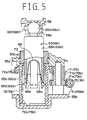
- a drive section C for tilting the mirror 57a and driving the wiper main body 60 is housed interiorly of the drive section casing 55.
- the drive section C is provided with a right-and-left motor 61 for tilting the mirror 57a in the right-and-left direction of the vehicular body, an up-and-down motor 62 for tilting the mirror 57a in the up-and-down direction of the vehicular body, a wiper motor 63 for driving the wiper main body 60, and a control circuit 64.
- the respective point ends of first to fourth rods 65 to 68 protrude from the drive section casing 55 and are coupled to the mirror casing 56.
- the first to the fourth rods 65 to 68 are equipped with spherical head portions 65a to 68a, cylindrical stem portions 65b to 68b, a plurality of leg portions 65c to 68c, and engagement protrusions 65d to 68d protruding outwardly of the two opposed leg portions 65c to 68c, respectively.
- Each rod is integrally formed by resin molding.
- a generally U-shaped spring 69 is inserted into the leg portion 65c (66c to 68c) to urge the leg portion 65c (66c to 68c) outward.
- the protruding portions 69a of the spring 69 engage with the engagement holes 65e (66e to 68e) of the leg portion 65c (66c to 68c), whereby the spring 69 is held by the leg portion 65c (66c to 68c).
- first to the fourth rods 65 to 68 are identical in shape with one another except that while the head portions 65a to 67a of the first to the third rods 65 to 67 are formed with a single protrusion (65f to 67f), the head portion 68a of the fourth rod 68 is formed with two protrusions 68f.
- a worm gear 70 is mounted on the output shaft 61a of the right-and-left motor 61. As shown in Fig. 3, this worm gear 70 meshes with the large-diameter gear 71a of a multi-stage gear 71.
- the small-diameter gear 71b of the multi-stage gear 71 meshes with the gear portion 72a of a cylindrical gear 72 which covers the proximal portion of the first rod 65.
- the inner wall surface of the cylindrical gear 72 is formed with a gear 72b, which in turn meshes with the engagement protrusion 65d of the first rod 65.
- the worm gear 70, multi-stage gear 71, and cylindrical gear 72 will rotate.
- the head portion 65a of the first rod 65 is connected by the protrusion 65f to the cylindrical engagement portion 58a of the base 58 so that it can roll and cannot rotate.
- the first rod 65 will be displaced according to the direction of rotation while being guided by the gear 72b, and consequently, the protrusion quantity of the first rod 65 from the drive section casing 65 will vary.
- the surface of the stem portion 65b of the first rod 65 is contacted by a packing 73 held on a cylindrical portion 55c formed in the cover 55a. With this, the drive section casing 55 is hermetically sealed.
- a worm gear 74 is mounted on the output shaft 62a of the up-and-down motor 62.
- the worm gear 74 meshes with the large-diameter gear 75a of a multi-stage gear 75.
- the small-diameter gear 75b of the multi-stage gear 75 meshes with the gear portion 76a of a cylindrical gear 76 which covers the proximal portion of the second rod 66.
- the engagement protrusion 66d of the second rod 66 meshes with the gear 76b of the cylindrical gear 76.
- the proximal portion of the third rod 67 is located within a cylindrical portion 55d formed in the cover 55b.
- the third rod 67 is displaced within the cylindrical portion 55d in correspondence to the displacements of the first and second rods 65 and 66.
- the cylindrical portion 55d is not formed with a gear similar to the above-mentioned gear 72b or 76b, the diameter of the cylindrical portion 55d is reduced so that the engagement protrusion 67d can elastically contact with the cylindrical portion 55d by the urging force of the leg portion 67c and spring 69.
- the third rod 67 can hold its position corresponding to the displacement based on the displacements of the first and second rods 65 and 66.
- a worm gear 77 is mounted on the output shaft 63a of the wiper motor 63.
- the worm gear 77 meshes with a first multi-stage gear 78, which in turn meshes with a second multi-stage gear 79.
- the second multi-stage gear 79 meshes with the large-diameter gear 80a of a third cylindrical multi-stage gear 80.
- the small-diameter gear 80b of the third multi-stage gear 80 meshes with the large-diameter gear 81a of a fourth multi-stage gear 81.
- the small-diameter gear 81b of the fourth multi-stage gear 81 meshes with a sensor gear 82.
- the bottom surface of the sensor gear 82 is provided with a plurality of protrusions (not shown), which are shifted from one another in radial and circumferential directions so that they can make contact with contacts 64a formed on a circuit board 64. With this arrangement, the revolution speed (or rotation quantity) of the sensor gear 82 is detected. Based on this result of detection, the drive of the wiper motor 63 is automatically stopped.
- the wiping of the mirror 57a does not need to be continued as in a wiper for a front windshield glass, for example. Therefore, at the time a wiping operation has been performed a predetermined number of times (e.g., thrice), the drive of the wiper motor 63 is automatically stopped.
- a predetermined number of times e.g., thrice
- the proximal portion of the fourth rod 68 engages with a slit 80c formed along the axial direction in the inner wall surface of the cylindrical multi-stage gear 80.
- the head portion 68a of the rod 68 is engaged by a transfer gear 83 provided within the mirror casing 56. If the engagement protrusions 68f of the head portion 68a of the fourth rod 68 engage with the slits 83a (Fig. 9) of this transfer gear 83, the fourth rod 68 cannot rotate relative to the transfer gear 83. Therefore, if the cylindrical multi-stage gear 80 rotates, the fourth rod 68 and transfer gear 83 will be rotated in interlock with the rotation of the multi-stage gear 80.
- the mirror casing 56 is provided with a link mechanism section D for converting the rotary motion of the wiper motor 63 to reciprocating motion and a rotary shaft section E connected to the link mechanism section D, as shown in Figs. 8 through 11.
- the link mechanism section D and rotary shaft section E are equipped with a driven gear 84 meshing with the transfer gear 83, a link arm 86 mounted at one end thereof on an eccentric shaft 85 provided in the driven gear 84, and a clutch plate 87 rotatably connected to the other end of the link arm 86. Furthermore, the link mechanism section D and rotary shaft section E are equipped with a plurality of balls 88 rollable on the surface of the clutch plate 87, a triangular holding clutch 89 for holding the balls 88 by recesses 89a, a coil spring 90 elastically contacting with the holding clutch 89, a cylindrical holding portion 91 inserting the coil spring 90 thereinto and also holding the holding clutch 89 so that the holding clutch cannot rotate, and a wiper shaft 93. The wiper shaft 93 is inserted through the cylindrical holding portion 91, holding clutch 89, and clutch plate 87 and is engaged by a washer 92 so that it is not pulled out from them.
- the driven gear 84 is rotatably supported on a supporting shaft 84a mounted in the mirror holder 57.
- the driven gear 84 is also formed with an insertion recess 84b into which one end of the eccentric shaft 85 is inserted.
- the clutch plate 87 is rotatable on the wiper shaft 93 and converts the reciprocating motion of the link arm 86 interlocking with the rotation of the driven gear 84 to reciprocal rotary motion.
- the clutch plate 87 is also formed with engagement holes 87a with which the balls 88 are always engaged by the urging force of the coil spring 90. Therefore, when an unexpected load exceeding the wiping range of the wiper main body 60 is exerted on the wiper main body 60, the balls 88 are disengaged from the engagement holes 87a. Therefore, an unexpected load is not transferred to components which leads from the clutch plate 87 to the wiper motor 63. This exhibits an effect of preventing damage to the wiper main body 60, damage to the wiper motor 63, and similar damage.
- the upper portion of the cylindrical holding portion 91 is formed with an external gear 91a.
- the cylindrical holding portion 91 holds the wiper shaft 93 so as to allow the relative rotation of the wiper shaft 93.
- the wiper main body 60 is coupled to the wiper shaft 93 through a screw 94.
- the wiper main body 60 is equipped with an arm head 95 covering the upper end of the cylindrical holding portion 91 and also having at its front surface a screw insertion portion 95a into which the screw 94 is inserted.
- the wiper main body 60 is equipped with a wiper arm 96 connected to the arm head 95, an arm piece 97 connected to the point end of the wiper arm 96, and a primary lever 98 coupled to the free end portion of the arm piece 97.
- the wiper main body 60 is equipped with secondary levers 99 pivotably coupled to both ends of the primary lever 98, a wiper blade 100 pivotably held on a vertebra (not shown) held over the secondary levers 99, and an arm position adjusting screw 101 inserted into a screw insertion portion 95b formed in the side wall surface of the arm head 95.
- the arm position adjusting screw 101 is formed with a worm gear 101a which meshes with the gear 91a of the cylindrical holding portion 91.
- the wiping range is offset, a screw driver is inserted into the head portion 101b of the arm position adjusting screw 101.
- the screw driver is rotated in a predetermined direction, the meshing position between the gear 91a and the worm gear 101a will be varied, and at the same time, the cylindrical holding portion 91, holding clutch 89, balls 88, and clutch plate 87 will be rotated.
- the wiping range of the wiper main body 60 can be finely adjusted.
- the fine adjustment to the wiping range by the arm position adjusting screw 101 can also be performed likewise even when the wiper main body 60 is attached to the wiper shaft 93 by the screw 94, so that the attachment of the wiper main body 60 can be readily performed.
- the clutch mechanism of the above-mentioned embodiment is constituted by the clutch plate 87 rotatably supported on the other end of the link arm 86, the balls 88 rollable on the surface of the clutch plate 87, and the triangular holding clutch 89 holding the balls 88 at the recesses 89a.
- the clutch mechanism may be formed as shown in Fig. 12. That is, a clutch plate 187 is rotatably supported on the other end of the link arm 86 and opposed to a generally triangular holding clutch 189.
- the triangular holding clutch 189 is formed with radial protrusions 189a which engage with slits 187a formed in the clutch plate 187.
- the protrusions 189a and slits 187a may be provided in the clutch plate 187 and the triangular holding clutch 189, respectively.
- the clutch plate 187 and triangular holding clutch 189 may have a combination of protrusions and slits. Even in these cases, the same effect as the aforementioned is obtainable.
- the wiping range to the mirror 57a can be made maximum. Also, even if there is a slight error when components are assembled, the essential wiping range will not vary, so the setting of the wiper operating angle and assembly operation can be made easy.
- the wiping range can be easily ensured by setting the wiper operating angle to an angle greater than an actual wiping range.
- a drive transfer member can be arranged in vicinity to the wiper shaft 93.
- the link arm 86 can be shortened. Moreover, since there is no need to provide the wiper motor on a side opposite to the wiper shaft 93 of the mirror 57a, the protrusion quantity of the rods 65 to 68 from the drive section casing 56 can be shortened, so that the thinning of the mirror body 50 is realizable.
Landscapes
- Engineering & Computer Science (AREA)
- Mechanical Engineering (AREA)
- Multimedia (AREA)
- Rear-View Mirror Devices That Are Mounted On The Exterior Of The Vehicle (AREA)
Claims (6)
- Wischeranordnung für einen Fahrzeugspiegel mit:einem Spiegelgehäuse (56) zum Halten eines Spiegels (57a),einer Wischer- Antriebseinrichtung (63, 64) aufgenommen in einem Antriebsabschnittsgehäuse (55);einer Wischerantriebs- Übertragungseinrichtung (78, 79, 80), untergebracht in dem Antriebsabschnittsgehäuse (55), um eine Drehung der Wischer-Antriebseinrichtung (63) zu übertragen;einem Verbindungsvorrichtungsabschnitt (D), untergebracht in dem Spiegelgehäuse (56) zum Umwandeln der durch die Wischerantriebs- Übertragungseinrichtung (78, 79, 80) übertragenen Drehung in eine hin- und hergehenden Bewegung;einem Drehwellenabschnitt (E), untergebracht in dem Spiegelgehäuse (56) zum Umwandeln der hin- und hergehenden Bewegung, umgewandelt durch den Verbindungsvorrichtungsabschnitt (D) in eine hin- und hergehende Drehbewegung;einem Wischerhauptkörper (60) zum Wischen einer Oberfläche des Spiegels (57a) durch die hin- und hergehende Drehbewegung, umgewandelt durch den Drehwellenabschnitt (E); dadurch gekennzeichnet, dass sie außerdem aufweisteine Spiegelneigungseinheit (61, 62), aufgenommen in dem Antriebsabschnittsgehäuse (55) zum Neigen des Spiegels (57a).
- Wischeranordnung nach Anspruch 1, außerdem mit:einer Einstelleinrichtung (101), vorgesehen in einem gekuppelten Abschnitt zwischen dem Wischerhauptkörper (60) und dem Drehwellenabschnitt (E) zum Einstellen einer relativen Position zwischen einem Drehbereich des Wischerhauptkörpers (60) und einem Drehbereich des Drehwellenabschnittes (E); undeiner einstellbaren Einrichtung (91a), untergebracht in dem Drehwellenabschnittes (E), wobei die einstellbare Einrichtung (91a) durch die Einstelleinrichtung (101) im Eingriff ergriffen ist.
- Wischeranordnung nach Anspruch 1, wobei die Wischerantriebs- Übertragungseinrichtung (78, 79, 80) mit einer drehbaren und variabel vorspringbaren Stange (68) ausgerüstet ist, wobei die von dem Antriebsabschnittsgehäuse (55) vorspringende Stange (68) auch mit dem Spiegelgehäuse (56) gekuppelt ist, und wobei die Stange (68) durch den Antrieb der Wischer- Antriebseinrichtung (63, 64) gedreht wird und auch der Antrieb der Wischer- Antriebseinrichtung (63, 64) zu dem Verbindungsvorrichtungsabschnitt (D) durch die Drehung der Stange (68) übertragen wird.
- Wischeranordnung nach Anspruch 1, außerdem mit einer Kupplungseinrichtung (87, 89) zum Lösen eines gekuppelten Zustandes zwischen dem Verbindungsvorrichtungsabschnitt (D) und dem Drehwellenabschnitt (E), wenn eine Belastung, die von dem Wischerhauptkörper (60) auf einen gekuppelten Abschnitt zwischen dem Verbindungsvorrichtungsabschnitt (D) und dem Drehwellenabschnitt (E) größer als eine vorbestimmte Belastung ist.
- Wischeranordnung nach Anspruch 4, wobei die Kupplungseinrichtung eine erste Platte (87) aufweist, vorgesehen auf einer Seite des Verbindungsvorrichtungsabschnittes (D), eine zweite Platte (89), vorgesehen auf einer Seite des Drehwellenabschnittes (E), und Kugeln (88), vorgesehen in einer der ersten oder zweiten Platte (87, 89) und mit der anderen Platte im Eingriff.
- Wischeranordnung nach Anspruch 4, wobei die Kupplungseinrichtung eine erste Platte (187) aufweist, vorgesehen auf einer Seite des Verbindungsvorrichtungsabschnittes (D), eine zweite Platte (189), vorgesehen auf einer Seite des Drehwellenabschnittes (E), und miteinander in Eingriff bringbare Vorsprünge (189a) und Ausnehmungen (187a), gebildet in der ersten und der zweiten Platte (187, 189).
Applications Claiming Priority (15)
| Application Number | Priority Date | Filing Date | Title |
|---|---|---|---|
| JP265559/97 | 1997-09-30 | ||
| JP26555897 | 1997-09-30 | ||
| JP26556097 | 1997-09-30 | ||
| JP26556197A JP3518278B2 (ja) | 1997-09-30 | 1997-09-30 | 車両ミラー用ワイパー |
| JP26555997 | 1997-09-30 | ||
| JP26556097 | 1997-09-30 | ||
| JP26556197 | 1997-09-30 | ||
| JP9265558A JPH1199912A (ja) | 1997-09-30 | 1997-09-30 | 車両外部電装品用ワイパー |
| JP265558/97 | 1997-09-30 | ||
| JP26555997A JP3482839B2 (ja) | 1997-09-30 | 1997-09-30 | 車両ミラー用ワイパー |
| JP265561/97 | 1997-09-30 | ||
| JP265560/97 | 1997-09-30 | ||
| JP5927798 | 1998-03-11 | ||
| JP10059277A JPH11165589A (ja) | 1997-09-30 | 1998-03-11 | 車両ミラー用ワイパー |
| JP59277/98 | 1998-03-11 |
Publications (3)
| Publication Number | Publication Date |
|---|---|
| EP0904983A2 EP0904983A2 (de) | 1999-03-31 |
| EP0904983A3 EP0904983A3 (de) | 2001-09-26 |
| EP0904983B1 true EP0904983B1 (de) | 2003-03-26 |
Family
ID=27523500
Family Applications (1)
| Application Number | Title | Priority Date | Filing Date |
|---|---|---|---|
| EP98203215A Expired - Lifetime EP0904983B1 (de) | 1997-09-30 | 1998-09-15 | Wischer für den Spiegel eines Kraftfahrzeuges |
Country Status (4)
| Country | Link |
|---|---|
| US (1) | US6058553A (de) |
| EP (1) | EP0904983B1 (de) |
| KR (1) | KR100288607B1 (de) |
| DE (1) | DE69812520T2 (de) |
Families Citing this family (18)
| Publication number | Priority date | Publication date | Assignee | Title |
|---|---|---|---|---|
| US6324718B1 (en) * | 1999-02-16 | 2001-12-04 | Subernia Y. Johnson | Side mounted retrofit wiper assembly |
| DE10134937A1 (de) * | 2001-07-18 | 2003-02-06 | Bosch Gmbh Robert | Getriebe-Antriebseinheit mit Drehzahlerfassung |
| JP4122734B2 (ja) * | 2001-07-23 | 2008-07-23 | 市光工業株式会社 | 自動車用リモートコントロール式ミラー装置 |
| DE10161975B4 (de) * | 2001-12-17 | 2005-10-13 | Em Kunststofftechnik Gmbh | Verstelleinheit, insbesondere für Kraftfahrzeug-Rückblickspiegel |
| US7370985B2 (en) * | 2002-12-30 | 2008-05-13 | Ian Boddy | Vehicular mirror with slip clutch for jack screw actuator |
| US7334906B2 (en) * | 2003-07-10 | 2008-02-26 | Ichikoh Industries, Ltd. | Outer mirror tilting apparatus |
| JP4319597B2 (ja) * | 2003-11-07 | 2009-08-26 | アスモ株式会社 | モータ装置、及びワイパモータ |
| KR101056175B1 (ko) * | 2003-11-07 | 2011-08-11 | 아스모 가부시키가이샤 | 출력샤프트 조립체, 모터장치 및 와이퍼 모터장치 |
| US7685670B2 (en) | 2003-11-07 | 2010-03-30 | Asmo Co., Ltd. | Motor apparatus and wiper motor apparatus |
| DE602004022003D1 (de) * | 2003-11-07 | 2009-08-27 | Asmo Co Ltd | Kupplungseinrichtung, Motor und Wischersystem |
| JP4217187B2 (ja) * | 2004-04-07 | 2009-01-28 | 株式会社村上開明堂 | ミラー位置検出装置 |
| US7669275B2 (en) * | 2004-11-16 | 2010-03-02 | Asmo Co., Ltd. | Clutch device and motor apparatus having the same |
| JP4408410B2 (ja) * | 2004-11-26 | 2010-02-03 | アスモ株式会社 | モータ装置及びワイパ装置 |
| US20070266515A1 (en) * | 2006-05-22 | 2007-11-22 | Chiang-Fen Lin | Wiper for an automobile rear-view mirror |
| DE102009014312A1 (de) * | 2009-03-25 | 2010-09-30 | Valeo Systèmes d'Essuyage | Elektromotorischer Hilfsantrieb, insbesondere Wischerantrieb |
| CN104129367B (zh) * | 2014-08-13 | 2015-12-30 | 余姚市利佛德汽车零部件有限公司 | 一种后视镜 |
| US20170297535A1 (en) * | 2016-04-15 | 2017-10-19 | GM Global Technology Operations LLC | Systems For Cleaning A Camera Mounted In A Side Mirror Or Other Vehicle Component |
| CN107499284A (zh) * | 2016-06-14 | 2017-12-22 | 通用汽车环球科技运作有限责任公司 | 用于清洁安装在侧镜或其它车辆部件中的摄像头的系统 |
Family Cites Families (6)
| Publication number | Priority date | Publication date | Assignee | Title |
|---|---|---|---|---|
| JPS6028702B2 (ja) * | 1979-07-31 | 1985-07-06 | 日産自動車株式会社 | ワイパ−付アウトサイドミラ− |
| IT8153115U1 (it) * | 1981-04-07 | 1982-10-07 | Vitaloni Spa | Specchio retrovisore esterno per autoveicoli |
| JPS59153636A (ja) * | 1983-02-18 | 1984-09-01 | Tokai Rika Co Ltd | ワイパ−付アウトサイドミラ− |
| US4870713A (en) * | 1988-07-21 | 1989-10-03 | Raynor George L | Self cleaning truck mirror |
| US5203090A (en) * | 1991-12-26 | 1993-04-20 | Bouska Bill R | Siding layout tool and method |
| JPH07304426A (ja) * | 1994-05-10 | 1995-11-21 | Ichikoh Ind Ltd | バックミラー用ワイパー |
-
1998
- 1998-09-09 KR KR1019980037077A patent/KR100288607B1/ko not_active Expired - Fee Related
- 1998-09-15 DE DE69812520T patent/DE69812520T2/de not_active Expired - Lifetime
- 1998-09-15 EP EP98203215A patent/EP0904983B1/de not_active Expired - Lifetime
- 1998-09-30 US US09/163,363 patent/US6058553A/en not_active Expired - Fee Related
Also Published As
| Publication number | Publication date |
|---|---|
| EP0904983A2 (de) | 1999-03-31 |
| DE69812520D1 (de) | 2003-04-30 |
| KR19990029644A (ko) | 1999-04-26 |
| US6058553A (en) | 2000-05-09 |
| EP0904983A3 (de) | 2001-09-26 |
| DE69812520T2 (de) | 2003-09-11 |
| KR100288607B1 (ko) | 2001-05-02 |
Similar Documents
| Publication | Publication Date | Title |
|---|---|---|
| EP0904983B1 (de) | Wischer für den Spiegel eines Kraftfahrzeuges | |
| EP0511203B1 (de) | Rückblickspiegel für kraftfahrzeug | |
| CN1318239C (zh) | 车辆用外反射镜 | |
| US6705660B2 (en) | Windshield wiper assembly | |
| JPH0681834U (ja) | 遠隔操作バックミラーのための記憶位置決め装置 | |
| US4403829A (en) | Angle adjusting arrangement for adjusting an element about two axes | |
| US7886400B2 (en) | Motor and wiper apparatus having the same | |
| US20040218297A1 (en) | Motorized retracting unit and motorized retractable rearview mirror | |
| US8234745B2 (en) | Motor device and wiper apparatus | |
| KR100316371B1 (ko) | 가압 대기형 윈드실드 와이퍼 장치 | |
| EP1468885B1 (de) | Scheibenwischermechanismus | |
| US4858268A (en) | Windshield wiper device for use in vehicles | |
| US4871246A (en) | Device for transmitting, without vibrations, movements from an electric control to a mirror-holder plate of a rearview mirror | |
| KR100637010B1 (ko) | 가역 기어 모터를 구비한 와이퍼 구동 메카니즘 | |
| GB2057627A (en) | Worm transmission mechanism for a periodically varying load | |
| AU2767592A (en) | Adjustable steering column assembly | |
| KR0173817B1 (ko) | 전조등의 광축조정장치 | |
| JP3482839B2 (ja) | 車両ミラー用ワイパー | |
| JPH1199912A (ja) | 車両外部電装品用ワイパー | |
| JP3518278B2 (ja) | 車両ミラー用ワイパー | |
| JPH11165589A (ja) | 車両ミラー用ワイパー | |
| JPH0536750Y2 (de) | ||
| EP0769436B1 (de) | Kraftfahrzeug-Scheibenwischer | |
| US5309599A (en) | Wiping device for windows of power vehicles | |
| KR101135102B1 (ko) | 유리 와이퍼 장치용 구동 장치 |
Legal Events
| Date | Code | Title | Description |
|---|---|---|---|
| PUAI | Public reference made under article 153(3) epc to a published international application that has entered the european phase |
Free format text: ORIGINAL CODE: 0009012 |
|
| AK | Designated contracting states |
Kind code of ref document: A2 Designated state(s): AT BE CH CY DE DK ES FI FR GB GR IE IT LI LU MC NL PT SE Kind code of ref document: A2 Designated state(s): DE FR GB SE |
|
| AX | Request for extension of the european patent |
Free format text: AL;LT;LV;MK;RO;SI |
|
| PUAL | Search report despatched |
Free format text: ORIGINAL CODE: 0009013 |
|
| AK | Designated contracting states |
Kind code of ref document: A3 Designated state(s): AT BE CH CY DE DK ES FI FR GB GR IE IT LI LU MC NL PT SE |
|
| AX | Request for extension of the european patent |
Free format text: AL;LT;LV;MK;RO;SI |
|
| RIC1 | Information provided on ipc code assigned before grant |
Free format text: 7B 60R 1/06 A, 7B 60R 1/072 B, 7B 60S 1/16 B, 7B 60S 1/18 B, 7B 60S 1/34 B |
|
| 17P | Request for examination filed |
Effective date: 20020315 |
|
| AKX | Designation fees paid |
Free format text: DE FR GB SE |
|
| GRAH | Despatch of communication of intention to grant a patent |
Free format text: ORIGINAL CODE: EPIDOS IGRA |
|
| GRAH | Despatch of communication of intention to grant a patent |
Free format text: ORIGINAL CODE: EPIDOS IGRA |
|
| GRAA | (expected) grant |
Free format text: ORIGINAL CODE: 0009210 |
|
| AK | Designated contracting states |
Designated state(s): DE FR GB SE |
|
| REG | Reference to a national code |
Ref country code: GB Ref legal event code: FG4D |
|
| REG | Reference to a national code |
Ref country code: SE Ref legal event code: TRGR |
|
| REF | Corresponds to: |
Ref document number: 69812520 Country of ref document: DE Date of ref document: 20030430 Kind code of ref document: P |
|
| ET | Fr: translation filed | ||
| PLBE | No opposition filed within time limit |
Free format text: ORIGINAL CODE: 0009261 |
|
| STAA | Information on the status of an ep patent application or granted ep patent |
Free format text: STATUS: NO OPPOSITION FILED WITHIN TIME LIMIT |
|
| 26N | No opposition filed |
Effective date: 20031230 |
|
| PGFP | Annual fee paid to national office [announced via postgrant information from national office to epo] |
Ref country code: FR Payment date: 20060908 Year of fee payment: 9 |
|
| PGFP | Annual fee paid to national office [announced via postgrant information from national office to epo] |
Ref country code: GB Payment date: 20060913 Year of fee payment: 9 |
|
| PGFP | Annual fee paid to national office [announced via postgrant information from national office to epo] |
Ref country code: SE Payment date: 20060906 Year of fee payment: 9 |
|
| PG25 | Lapsed in a contracting state [announced via postgrant information from national office to epo] |
Ref country code: SE Free format text: LAPSE BECAUSE OF NON-PAYMENT OF DUE FEES Effective date: 20070916 |
|
| EUG | Se: european patent has lapsed | ||
| GBPC | Gb: european patent ceased through non-payment of renewal fee |
Effective date: 20070915 |
|
| REG | Reference to a national code |
Ref country code: FR Ref legal event code: ST Effective date: 20080531 |
|
| PG25 | Lapsed in a contracting state [announced via postgrant information from national office to epo] |
Ref country code: FR Free format text: LAPSE BECAUSE OF NON-PAYMENT OF DUE FEES Effective date: 20071001 |
|
| PG25 | Lapsed in a contracting state [announced via postgrant information from national office to epo] |
Ref country code: GB Free format text: LAPSE BECAUSE OF NON-PAYMENT OF DUE FEES Effective date: 20070915 |
|
| PGFP | Annual fee paid to national office [announced via postgrant information from national office to epo] |
Ref country code: DE Payment date: 20110907 Year of fee payment: 14 |
|
| PG25 | Lapsed in a contracting state [announced via postgrant information from national office to epo] |
Ref country code: DE Free format text: LAPSE BECAUSE OF NON-PAYMENT OF DUE FEES Effective date: 20130403 |
|
| REG | Reference to a national code |
Ref country code: DE Ref legal event code: R119 Ref document number: 69812520 Country of ref document: DE Effective date: 20130403 |