EP0904959A2 - Radialer Luftreifen und Verfahren zu seiner Herstellung - Google Patents
Radialer Luftreifen und Verfahren zu seiner Herstellung Download PDFInfo
- Publication number
- EP0904959A2 EP0904959A2 EP98116884A EP98116884A EP0904959A2 EP 0904959 A2 EP0904959 A2 EP 0904959A2 EP 98116884 A EP98116884 A EP 98116884A EP 98116884 A EP98116884 A EP 98116884A EP 0904959 A2 EP0904959 A2 EP 0904959A2
- Authority
- EP
- European Patent Office
- Prior art keywords
- strip
- tire
- belt layer
- pieces
- strip pieces
- Prior art date
- Legal status (The legal status is an assumption and is not a legal conclusion. Google has not performed a legal analysis and makes no representation as to the accuracy of the status listed.)
- Ceased
Links
Images

Classifications
-
- B—PERFORMING OPERATIONS; TRANSPORTING
- B60—VEHICLES IN GENERAL
- B60C—VEHICLE TYRES; TYRE INFLATION; TYRE CHANGING; CONNECTING VALVES TO INFLATABLE ELASTIC BODIES IN GENERAL; DEVICES OR ARRANGEMENTS RELATED TO TYRES
- B60C9/00—Reinforcements or ply arrangement of pneumatic tyres
- B60C9/18—Structure or arrangement of belts or breakers, crown-reinforcing or cushioning layers
- B60C9/20—Structure or arrangement of belts or breakers, crown-reinforcing or cushioning layers built-up from rubberised plies each having all cords arranged substantially parallel
-
- B—PERFORMING OPERATIONS; TRANSPORTING
- B29—WORKING OF PLASTICS; WORKING OF SUBSTANCES IN A PLASTIC STATE IN GENERAL
- B29D—PRODUCING PARTICULAR ARTICLES FROM PLASTICS OR FROM SUBSTANCES IN A PLASTIC STATE
- B29D30/00—Producing pneumatic or solid tyres or parts thereof
- B29D30/06—Pneumatic tyres or parts thereof (e.g. produced by casting, moulding, compression moulding, injection moulding, centrifugal casting)
- B29D30/38—Textile inserts, e.g. cord or canvas layers, for tyres; Treatment of inserts prior to building the tyre
- B29D30/46—Cutting textile inserts to required shape
-
- Y—GENERAL TAGGING OF NEW TECHNOLOGICAL DEVELOPMENTS; GENERAL TAGGING OF CROSS-SECTIONAL TECHNOLOGIES SPANNING OVER SEVERAL SECTIONS OF THE IPC; TECHNICAL SUBJECTS COVERED BY FORMER USPC CROSS-REFERENCE ART COLLECTIONS [XRACs] AND DIGESTS
- Y10—TECHNICAL SUBJECTS COVERED BY FORMER USPC
- Y10S—TECHNICAL SUBJECTS COVERED BY FORMER USPC CROSS-REFERENCE ART COLLECTIONS [XRACs] AND DIGESTS
- Y10S156/00—Adhesive bonding and miscellaneous chemical manufacture
- Y10S156/906—Off-drum manufacture of tire fabric or ply
- Y10S156/907—Off-drum manufacture of tire fabric or ply including assembly of bias-cut fabric
-
- Y—GENERAL TAGGING OF NEW TECHNOLOGICAL DEVELOPMENTS; GENERAL TAGGING OF CROSS-SECTIONAL TECHNOLOGIES SPANNING OVER SEVERAL SECTIONS OF THE IPC; TECHNICAL SUBJECTS COVERED BY FORMER USPC CROSS-REFERENCE ART COLLECTIONS [XRACs] AND DIGESTS
- Y10—TECHNICAL SUBJECTS COVERED BY FORMER USPC
- Y10T—TECHNICAL SUBJECTS COVERED BY FORMER US CLASSIFICATION
- Y10T156/00—Adhesive bonding and miscellaneous chemical manufacture
- Y10T156/10—Methods of surface bonding and/or assembly therefor
- Y10T156/1052—Methods of surface bonding and/or assembly therefor with cutting, punching, tearing or severing
- Y10T156/1062—Prior to assembly
- Y10T156/1075—Prior to assembly of plural laminae from single stock and assembling to each other or to additional lamina
Definitions
- the present invention relates to a pneumatic radial tire and manufacturing method of the same, and more particularly to a pneumatic radial tire which enables many kinds productions in small quantities to be efficiently performed and manufacturing method of the same.
- a belt layer for a pneumatic radial tire is formed in a manner that a wide calender material calendered to impregnate a number of reinforcing cords with unvulcanized rubber is bias-cut to a width of a belt, the reinforcing cords having been pulled out from a creel stand and aligned with one another, a number of cut pieces obtained by the bias-cutting are joined together for forming a long belt sheet material where the cut ends thereof are left and right edges, and then this long sheet material is wound on a drum and placed in temporary stock.
- a belt member for one tire is obtained by pulling out the belt sheet material from the drum during belt layer formation and cutting the sheet material to a length equal to a circumference of the belt layer in a direction along the reinforcing cords.
- a belt member for one tire is different from another in width and length depending on a tire size.
- belt sheet materials different from one another must be stocked for respective tire specifications.
- a great many kinds of belt members were stocked, which created a problem of requiring wide stock space.
- the impossibility of utilizing a belt member for the other tire specifications leads to such problems of leaving end portions of belt sheet materials for respective tire specifications as waste and requiring more operations during a tire manufacturing process.
- the object of the present invention is to solve the above described problems of stock space for belt members for respective tire specifications and material waste, and also is to provide a pneumatic radial tire which enables production of many kinds in small quantities to be efficiently performed and manufacturing method of the same.
- a pneumatic radial tire of the present invention has a belt layer disposed radially outer to a carcass layer in a tread section of the tire, the belt layer being formed of strip pieces each comprising a plurality of reinforcing cords and having a predetermined width, the strip pieces being arranged at a predetermined angle relative to the circumferential direction of the tire, one round portion of the belt layer in the circumferential direction of the tire comprising an integral number of the strip pieces juxtaposed in a manner such that each two adjacent strip pieces butts against each other along their longitudinal edges.
- the strip pieces are obtained by cutting a strip material having a predetermined width to a predetermined length at a predetermined angle.
- the method manufacturing of a pneumatic radial tire of the present invention comprises the steps of feeding a strip material comprising a plurality of reinforcing cords and having a predetermined width from a standard measure feeding device which is adjustable in its feeding angle to a carrier conveyor, cutting said strip material to a predetermined size in sequence to form strip pieces while alternately moving the strip material and the carrier conveyor intermittently in synchronization with each other, transferring the strip pieces onto the carrier conveyor, forming a belt member having a length equal to a length L of a belt layer for one tire by butting the strip pieces against each other along their longitudinal edges, and using the belt member as the belt layer.
- a belt layer for one round of a tire is formed by inclining at a predetermined angle the integral number of predetermined width strip pieces, each of which is composed of a plurality of reinforcing cords, and by joining these strip pieces together in a manner such that two adjacent strip pieces butts against each other along their longitudinal edges.
- the predetermined width strip material is cut to a predetermined size in sequence at a predetermined inclined angle, the integral number of strip pieces obtained by cutting are butted against one another along their longitudinal edges and thereby the belt layer can be formed to have a length for one tire.
- Fig. 1 shown is an example of a pneumatic radial tire of the present invention, where reference numerals 1, 2 and 3 denote a tread section, a side wall section and a bead section respectively.
- a carcass layer 4 is disposed in the inner side of the tire, and both end portions 4a thereof are folded from the tire inner side to its outer side around bead cores 5 so as to hold bead fillers 6.
- Two belt layers 7A and 7B are provided in the outer peripheral side of the carcass layer 4.
- a reference numeral 8 denotes an inner liner layer disposed in the inner side of the tire.
- the belt layers 7A and 7B are formed for one round of a tire by inclining the integral number of predetermined width strip pieces S1, S2, S3,... at a predetermined angle relative to the circumferential direction T of the tire, each of which is composed of a plurality of reinforcing cords f, and then joining these strip pieces together in a manner such that two adjacent strip pieces butts against each other along their longitudinal edges. Between the belt layers, the reinforcing cords f cross each other with their inclinations to the tire circumferential direction T reversed to each other.
- an inclined angle of each of the strip pieces S1, S2, S3,..., to the tire circumferential direction T is ⁇ (° ) and the number of strip pieces S1, S2, S3,..., is N
- ⁇ sin -1 (N ⁇ A/L)
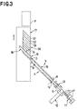
- the pneumatic radial tire constructed in the above manner employs an usual method for forming the inner liner layer, the carcass layer, the bead cores having bead fillers and a carcass band having side wall rubber by means of a band forming drum. But the belt layers are formed as shown in Fig. 3.
- FIG. 3 shown is a pneumatic radial tire manufacturing method of the present invention, where reference numeral 11 denotes the creel stand for feeding a plurality of reinforcing cords f, 12; a rubber coating device for coating the reinforcing cords f with unvulcanized rubber to form a strip material S, 13; a drawing device for drawing the strip material S in an arrow direction, 14; a festooner for temporarily holding the strip material S, 15; a standard measure feeding device for intermittently carrying the strip material S, 16; a bias cutter for obliquely cutting the strip material S, 17; a carrier conveyor for intermittently carrying strip pieces obtained by cutting of the bias cutter 16 toward a belt forming drum F side and 18; a splicer for butting the sides of the strip pieces against those of the others and joining the strip pieces together.
- reference numeral 11 denotes the creel stand for feeding a plurality of reinforcing cords f, 12; a rubber coating device for coating the reinforcing cord
- the standard measure feeding device 15 can be rotated and moved in both sides indicated by arrow directions X around a position O of the bias cutter 16 side.
- the standard measure feeding device 15 can adjust an angle for feeding the strip material S to the carrier conveyor 17.
- the standard measure feeding device 15 and the carrier conveyor 17 can alternately move the strip material S intermittently in synchronization with each other.
- the splicer 18 can change a direction of joining accompanied with the standard measure feeding device 15 rotated and moved so as to change the cutting angle ⁇ of the bias cutter 16.
- the splicer 18 can always perform splicing along the longitudinal edges of the strip pieces.
- Formation of a belt layer is carried out as follows. First, a plurality of reinforcing cords f fed from the creel stand 11 and aligned are coated with unvulcanized rubber by the rubber coating device 12 to continuously form a predetermined width strip material S. A predetermined amount of the strip material S is carried to the carrier conveyor 17 side only by a predetermined distance by the standard measure feeding device 15 via the drawing device 13 and the festooner 14. Then, the strip material S is cut to a predetermined size by the bias cutter 16 with a predetermined cutting angle ⁇ set with respect to the longitudinal direction (feeding direction) of the strip material S, which is equivalent to the moving direction of the standard measure feeding device.
- the cutting angle ⁇ is identical to the above inclined angle ⁇ and set such that N can be an integer in the above expression.
- A means a width of the strip material S which is equal to a width of the strip piece.
- a strip piece S1 obtained by the above predetermined-size cutting is transferred to the carrier conveyor 17 and then carried thereon by an amount equal to a length of its cut surface to the forming drum F side.
- the strip material S is carried again by a predetermined length by the standard measure feeding device 15.
- the strip material S carried to the carrier conveyor 17 side adjacently to the strip piece S1 is bias-cut by the bias cutter 16.
- the splicer 18 the strip pieces S1 and S2 are joined together by butting the side of one against that of the other.
- the joined strip pieces S1 and S2 are carried on the carrier conveyor 17 by length equal to that of their cut surfaces.
- a belt member 7A' is formed, which is composed of the integral number of strip pieces S1, S2, S3,..., of equal width, and has a length equal to the length L of the belt layer 7A for one tire.
- the belt member 7A' is wound on the belt forming drum F by one round to form an unvulcanized rubber belt layer 7A where the reinforcing cords f are inclined in one direction. Since a belt layer is directly formed without stocking any belt members, stock space is unnecessary. Also, since the belt layer 7A is formed by using the integral number of strip pieces S1, S2, S3,..., of equal width, the occurrence of material waste is prevented.
- Formation of the belt layer 7B of the outer side is also carried out by inclining the reinforcing cords f in the reverse direction of the above described direction for 7A, and similarly, a belt member which is composed of the integral number of strip pieces having equal width is formed. Then, the belt member is wound on the belt layer 7A around a belt forming drum F by one round, a belt layer 7B of unvulcanized rubber is formed with the reinforcing cords f inclined in the other direction. The belt member for the belt layer 7B is cut and placed on the carrier conveyor 17 by one tire length as the same with the belt layer 7A. When the belt layer 7B is wound around the drum, the belt drum is rotated in the opposite direction of that for the belt layer 7A, and the belt layer 7B is formed.
- tread rubber is wound on the belt layer by one round and then a belt tread rubber laminated body is formed.
- the carcass band is deformed to be troidal by a shaping drum, and the belt tread rubber laminated body is transferred to its outer periphery. Then, the belt tread rubber laminated body is stuck to the troidal carcass band without any space left to be formed into a green tire.
- the above described pneumatic radial tire can be provided.
- a feeding length of the strip material S sent by the standard measure feeding device 15 to the carrier conveyor 17 is changed.
- an angle ⁇ for cutting the strip material S by the bias cutter 16 is changed according to the changed length L such that N can be an integer in the above expression.
- Changing of the cutting angle ⁇ is carried out by rotating and moving the standard measure feeding device 15 around the position O and changing an angle for feeding the strip material S to the carrier conveyor 17. Since the splicer 18 is installed in the same frame as that for the standard measure feeding device, its arranging angle is changed accompanied with the angle change of the standard measure feeding device.
- a feeding length by the carrier conveyor 17 is also changed according to the above described angle change.
- Strip pieces obtained by cutting the strip material S after the specification change are then joined together, as in the above case, while butting the sides of one piece with those of the others in sequence and thereby a belt member composed of the integral number of strip pieces is formed.
- each changing of tire specifications was dealt with by replacing a drum having taken up a long belt sheet material against another.
- many kinds of tires having different sizes can be dealt with only by changing, as described above, a cutting angle ⁇ according to a change in tire specifications. Accordingly, efficient production of many kinds in small quantities can be performed without any necessity of securing stock space for respective tire specifications and without carrying out any large-scale setup changing work.
- the integral number of predetermined width strip pieces S1, S2, S3,..., each composed of a plurality of reinforcing cords f are inclined by a predetermined angle relative to the tire circumferential direction T, these strip pieces are joined together while both sides of one piece are butted against those of the others in sequence and thereby a belt layer for one tire is provided.
- a predetermined width strip material S composed of a plurality of reinforcing cords f is placed on the carrier conveyor 17 such that its feeding angle can be adjusted.
- the strip material S and the carrier conveyor 17 are alternately moved intermittently in synchronization with each other, and the strip material S is cut to a predetermined size in sequence to make strip pieces.
- the strip pieces are transferred to the carrier conveyor 17, and the sides of the strip pieces are butted against those of the others to form a belt member having a length equal to a length of a belt layer for one tire. Then, the belt member can be used as a belt layer for a tire.
- an angle ⁇ for cutting the strip material S to a predetermined size is set such that N can be an integer in the above expression.
- the number N of strip pieces can be set to 73.
- a length L of a belt layer is 1800mm and a width A of a strip material S is 20mm
- a cutting angle ⁇ is 24.3°
- the number N of strip pieces can be set to 37. Even if a tire size is changed, by similarly changing a cutting angle ⁇ , the number N of strip pieces can be set to an integer.
- Table 1 shows a case where a length L of a belt layer is 1800mm and a width A of a strip material S is 10mm.
- Table 2 shows a case where a length L of a belt layer is 1800mm and a width A of a strip material S is 20mm.
- Table 3 shows a case where a length L of a belt layer is 1800mm and a width A of a strip material S is 30mm.
- a width A of a strip material S should be set within a range of 5 to 60mm, preferably 10 to 30mm.
- a cutting angle ⁇ should be set within a range of 15 to 45° , preferably 20 to 30° .
- the above ranges of a width A of a strip material S and a cutting angle ⁇ can be respectively applied to a width A of a strip piece and an inclined angle ⁇ .
- the strip material S was provided by coating the reinforcing cords f supplied from the creel stand 11 with rubber by the rubber coating device 12. Instead, a long strip material S having a predetermined width formed and taken up by the drum beforehand may be also provided.
Landscapes
- Engineering & Computer Science (AREA)
- Mechanical Engineering (AREA)
- Textile Engineering (AREA)
- Tyre Moulding (AREA)
- Tires In General (AREA)
Applications Claiming Priority (3)
| Application Number | Priority Date | Filing Date | Title |
|---|---|---|---|
| JP261404/97 | 1997-09-26 | ||
| JP26140497 | 1997-09-26 | ||
| JP9261404A JPH1199564A (ja) | 1997-09-26 | 1997-09-26 | 空気入りラジアルタイヤ及びその製造方法 |
Publications (2)
| Publication Number | Publication Date |
|---|---|
| EP0904959A2 true EP0904959A2 (de) | 1999-03-31 |
| EP0904959A3 EP0904959A3 (de) | 2000-11-29 |
Family
ID=17361407
Family Applications (1)
| Application Number | Title | Priority Date | Filing Date |
|---|---|---|---|
| EP98116884A Ceased EP0904959A3 (de) | 1997-09-26 | 1998-09-07 | Radialer Luftreifen und Verfahren zu seiner Herstellung |
Country Status (3)
| Country | Link |
|---|---|
| US (1) | US6669798B1 (de) |
| EP (1) | EP0904959A3 (de) |
| JP (1) | JPH1199564A (de) |
Cited By (8)
| Publication number | Priority date | Publication date | Assignee | Title |
|---|---|---|---|---|
| EP1040908A3 (de) * | 1999-03-30 | 2001-05-02 | The Yokohama Rubber Co., Ltd. | Verfahren zum Zuführen von Gürtellagen |
| EP1211058A1 (de) * | 2000-11-29 | 2002-06-05 | PIRELLI PNEUMATICI Società per Azioni | Verfahren und Vorrichtung zur Herstellung einer Gürtelbandage eines Luftreifens |
| EP1065043A3 (de) * | 1999-06-28 | 2002-09-11 | The Yokohama Rubber Co., Ltd. | Verfahren und Vorrichtung zur Herstellung von bandförmigen Elementen |
| WO2003070453A1 (fr) * | 2002-02-22 | 2003-08-28 | Bridgestone Corporation | Procede de production d'element en caoutchouc mince, dispositif de calandrage de caoutchouc, et procede de calandrage de caoutchouc |
| WO2004056558A1 (en) * | 2002-12-23 | 2004-07-08 | Vmi Epe Holland B.V. | Device and method for producing a breaker ply |
| WO2004065110A1 (ja) * | 2003-01-22 | 2004-08-05 | Bridgestone Corporation | タイヤ補強層の形成装置 |
| US7172005B2 (en) | 2000-11-29 | 2007-02-06 | Pirelli Pneumatici S.P.A. | Apparatus for manufacturing a vehicle tire and a belt structure, belt package and crown structure of the tire |
| US9770859B2 (en) | 2014-12-18 | 2017-09-26 | The Goodyear Tire & Rubber Company | Apparatus for producing laminated fabric ply strips |
Families Citing this family (22)
| Publication number | Priority date | Publication date | Assignee | Title |
|---|---|---|---|---|
| JP4259698B2 (ja) * | 1999-10-12 | 2009-04-30 | 横浜ゴム株式会社 | ベルト部材の製造方法及びその装置 |
| JP4259704B2 (ja) * | 1999-12-07 | 2009-04-30 | 横浜ゴム株式会社 | タイヤ成形システム及び成形方法 |
| JP4894080B2 (ja) * | 2000-05-17 | 2012-03-07 | 横浜ゴム株式会社 | カーカス部材の製造方法及びその装置 |
| BR0112009B1 (pt) * | 2000-06-29 | 2011-06-14 | processo e planta para fabricar uma estrutura de cinta de um pneu cru. | |
| US7008495B2 (en) * | 2000-06-29 | 2006-03-07 | Pirelli Pneumatici S.P.A. | Method and plant for manufacturing a belt structure, a belt package, and a crown structure for a vehicle tire |
| JP4653377B2 (ja) * | 2002-10-07 | 2011-03-16 | 住友ゴム工業株式会社 | ストリップ片接合体の製造方法、及びそれに用いるストリップ片接合体の製造装置 |
| JP4346436B2 (ja) * | 2003-12-25 | 2009-10-21 | 横浜ゴム株式会社 | 空気入りタイヤ及びその製造方法 |
| JP4500075B2 (ja) * | 2004-03-22 | 2010-07-14 | 住友ゴム工業株式会社 | 空気入りタイヤ |
| WO2006106562A1 (ja) * | 2005-03-29 | 2006-10-12 | Toyo Tire & Rubber Co., Ltd. | タイヤ用ベルトの製造方法及び装置 |
| JP4532550B2 (ja) * | 2005-07-15 | 2010-08-25 | 東洋ゴム工業株式会社 | ベルト部材の製造方法 |
| DE112006003710T5 (de) | 2006-01-30 | 2008-12-11 | Toyo Tire & Rubber Co., Ltd. | Verfahren und Vorrichtung zum Anheften und Aufbauen eines Gürtelelements |
| DE112006003747T5 (de) | 2006-02-15 | 2008-12-24 | Toyo Tire & Rubber Co., Ltd. | Verfahren und Vorrichtung zum Befestigen von Gürtelkantenbandagen |
| DE112006003858B4 (de) | 2006-04-21 | 2020-06-04 | Toyo Tire & Rubber Co., Ltd. | Verfahren und Vorrichtung zum Verbinden von bandartigem Material |
| BRPI0721788B1 (pt) * | 2007-06-29 | 2018-07-03 | Pirelli Tyre S.P.A. | Processo e aparelho para a fabricação de pneus para rodas de veículos |
| US20100175812A1 (en) * | 2007-08-21 | 2010-07-15 | Toyo Tire & Rubber Co., Ltd. | Method of and apparatus for manufacturing a belt member |
| US8535465B2 (en) * | 2007-11-30 | 2013-09-17 | Pirelli Tyre S.P.A. | Process and apparatus for manufacturing tyres for vehicle wheels |
| WO2010073055A1 (en) * | 2008-12-22 | 2010-07-01 | Pirelli Tyre S.P.A. | Tyre for two -wheeled vehicle and process for manufacturing the same |
| EP2516142B1 (de) * | 2009-12-22 | 2015-04-08 | Pirelli Tyre S.p.A. | Verfahren und anlage zur herstellung verschiedenen arten von rohreifen für fahrzeugräder |
| JP6648771B2 (ja) | 2018-02-16 | 2020-02-14 | 横浜ゴム株式会社 | タイヤの製造方法 |
| FR3088566B3 (fr) * | 2018-11-16 | 2020-11-13 | Michelin & Cie | Systeme de coupe de bandelettes par couteaux helicoidaux et procede de coupe correspondant |
| JP2023038118A (ja) * | 2021-09-06 | 2023-03-16 | 株式会社ブリヂストン | タイヤ及びタイヤの製造方法 |
| KR102785932B1 (ko) * | 2021-10-27 | 2025-03-25 | 금호타이어 주식회사 | 공기입 타이어 |
Family Cites Families (8)
| Publication number | Priority date | Publication date | Assignee | Title |
|---|---|---|---|---|
| US2295542A (en) * | 1938-07-06 | 1942-09-15 | Gen Tire & Rubber Co | Band building drum |
| GB1039608A (en) * | 1962-05-11 | 1966-08-17 | Du Pont | Improvements in or relating to pneumatic tyre manufacture |
| US3694283A (en) * | 1966-07-13 | 1972-09-26 | Goodrich Co B F | Wire overhead |
| US3802982A (en) * | 1970-01-06 | 1974-04-09 | Steelastic Co | Reinforced tire fabric and method and apparatus for making same |
| US3682222A (en) * | 1970-01-06 | 1972-08-08 | Steelastic Co | Pneumatic tire having helical reinforcing filaments |
| US3803965A (en) * | 1972-05-24 | 1974-04-16 | Steelastic Co | Apparatus for producing reinforced fabric |
| LU77915A1 (de) * | 1976-08-27 | 1977-11-14 | ||
| JPS5462285A (en) * | 1977-10-28 | 1979-05-19 | Bridgestone Corp | Reinforcing material for rubber and its preparation |
-
1997
- 1997-09-26 JP JP9261404A patent/JPH1199564A/ja active Pending
-
1998
- 1998-08-27 US US09/141,316 patent/US6669798B1/en not_active Expired - Fee Related
- 1998-09-07 EP EP98116884A patent/EP0904959A3/de not_active Ceased
Cited By (11)
| Publication number | Priority date | Publication date | Assignee | Title |
|---|---|---|---|---|
| EP1040908A3 (de) * | 1999-03-30 | 2001-05-02 | The Yokohama Rubber Co., Ltd. | Verfahren zum Zuführen von Gürtellagen |
| EP1419877A3 (de) * | 1999-03-30 | 2004-05-26 | The Yokohama Rubber Co., Ltd. | Verfahren zum Zuführen von Gürtellagen |
| KR100653110B1 (ko) * | 1999-03-30 | 2006-12-04 | 요코하마 고무 가부시키가이샤 | 벨트재 공급 방법 |
| EP1065043A3 (de) * | 1999-06-28 | 2002-09-11 | The Yokohama Rubber Co., Ltd. | Verfahren und Vorrichtung zur Herstellung von bandförmigen Elementen |
| EP1211058A1 (de) * | 2000-11-29 | 2002-06-05 | PIRELLI PNEUMATICI Società per Azioni | Verfahren und Vorrichtung zur Herstellung einer Gürtelbandage eines Luftreifens |
| US7172005B2 (en) | 2000-11-29 | 2007-02-06 | Pirelli Pneumatici S.P.A. | Apparatus for manufacturing a vehicle tire and a belt structure, belt package and crown structure of the tire |
| WO2003070453A1 (fr) * | 2002-02-22 | 2003-08-28 | Bridgestone Corporation | Procede de production d'element en caoutchouc mince, dispositif de calandrage de caoutchouc, et procede de calandrage de caoutchouc |
| WO2004056558A1 (en) * | 2002-12-23 | 2004-07-08 | Vmi Epe Holland B.V. | Device and method for producing a breaker ply |
| WO2004065110A1 (ja) * | 2003-01-22 | 2004-08-05 | Bridgestone Corporation | タイヤ補強層の形成装置 |
| US7487814B2 (en) | 2003-01-22 | 2009-02-10 | Bridgestone Corporation | Device of forming tire reinforcing layer |
| US9770859B2 (en) | 2014-12-18 | 2017-09-26 | The Goodyear Tire & Rubber Company | Apparatus for producing laminated fabric ply strips |
Also Published As
| Publication number | Publication date |
|---|---|
| EP0904959A3 (de) | 2000-11-29 |
| JPH1199564A (ja) | 1999-04-13 |
| US6669798B1 (en) | 2003-12-30 |
Similar Documents
| Publication | Publication Date | Title |
|---|---|---|
| EP0904959A2 (de) | Radialer Luftreifen und Verfahren zu seiner Herstellung | |
| RU2331518C2 (ru) | Способ и устройство для сборки шин для колес транспортных средств | |
| US5328532A (en) | Method of forming ply member | |
| JP4523601B2 (ja) | タイヤの成型方法及び成型設備 | |
| EP0246497A2 (de) | Verfahren zum Herstellen von Radialreifenkarkassenrohlingen für Fahrzeuge | |
| CN102762361B (zh) | 用于构造用于车辆车轮的生轮胎的处理和设备 | |
| US10800123B2 (en) | Process and apparatus for manufacturing tyres | |
| US20180001584A1 (en) | Process for building tyres and tyre obtained thereby | |
| KR102033973B1 (ko) | 타이어의 벨트 및 트레드를 제조하기 위한 드럼 | |
| CN100480067C (zh) | 充气轮胎及其制造方法 | |
| PL180193B1 (pl) | S posób wytwarzania laminatu stanowiacego element skladowy opony, zwlaszcza do ksztaltowania osnowy korpusu radialnej opony pneumatyczneji urzadzenie do wytwarzania laminatu stanowiacego element skladowy opony, zwlaszcza do ksztaltowania osnowy korpusu radialnej opony pneumatycznej PL PL PL PL PL PL PL | |
| EP1652658B1 (de) | Verfahren und Vorrichtung zur Herstellung einer Reifeneinlage oder einer anderen Verstärkungslage mittels streifen | |
| KR100913650B1 (ko) | 타이어 조립 방법 | |
| JP5243448B2 (ja) | 異なる幅を有するストリップの付与によるタイヤの製造方法 | |
| EP1555113A1 (de) | Verfahren und vorrichtung zur herstellung einer cordverstärkungslage für reifen | |
| JP4134030B2 (ja) | タイヤ構成部材の製造方法および空気入りタイヤ | |
| US8029632B2 (en) | Method for producing a belt package for a pneumatic vehicle tire | |
| JP4402415B2 (ja) | タイヤ用コード補強層の形成方法およびコード補強層形成装置 | |
| JP4383813B2 (ja) | 空気入りタイヤの製造方法 |
Legal Events
| Date | Code | Title | Description |
|---|---|---|---|
| PUAI | Public reference made under article 153(3) epc to a published international application that has entered the european phase |
Free format text: ORIGINAL CODE: 0009012 |
|
| AK | Designated contracting states |
Kind code of ref document: A2 Designated state(s): DE FR GB IT NL |
|
| AX | Request for extension of the european patent |
Free format text: AL;LT;LV;MK;RO;SI |
|
| PUAL | Search report despatched |
Free format text: ORIGINAL CODE: 0009013 |
|
| AK | Designated contracting states |
Kind code of ref document: A3 Designated state(s): AT BE CH CY DE DK ES FI FR GB GR IE IT LI LU MC NL PT SE |
|
| AX | Request for extension of the european patent |
Free format text: AL;LT;LV;MK;RO;SI |
|
| 17P | Request for examination filed |
Effective date: 20010214 |
|
| AKX | Designation fees paid |
Free format text: DE FR GB IT NL |
|
| 17Q | First examination report despatched |
Effective date: 20020619 |
|
| STAA | Information on the status of an ep patent application or granted ep patent |
Free format text: STATUS: THE APPLICATION HAS BEEN REFUSED |
|
| 18R | Application refused |
Effective date: 20040112 |