EP0904944A2 - Imprimante et méthode pour former de tailles multiples d'éléments d'image sur matériau photosensible - Google Patents
Imprimante et méthode pour former de tailles multiples d'éléments d'image sur matériau photosensible Download PDFInfo
- Publication number
- EP0904944A2 EP0904944A2 EP98203094A EP98203094A EP0904944A2 EP 0904944 A2 EP0904944 A2 EP 0904944A2 EP 98203094 A EP98203094 A EP 98203094A EP 98203094 A EP98203094 A EP 98203094A EP 0904944 A2 EP0904944 A2 EP 0904944A2
- Authority
- EP
- European Patent Office
- Prior art keywords
- aperture
- photosensitive media
- light beam
- light source
- image pixel
- Prior art date
- Legal status (The legal status is an assumption and is not a legal conclusion. Google has not performed a legal analysis and makes no representation as to the accuracy of the status listed.)
- Withdrawn
Links
Images


Classifications
-
- B—PERFORMING OPERATIONS; TRANSPORTING
- B41—PRINTING; LINING MACHINES; TYPEWRITERS; STAMPS
- B41J—TYPEWRITERS; SELECTIVE PRINTING MECHANISMS, i.e. MECHANISMS PRINTING OTHERWISE THAN FROM A FORME; CORRECTION OF TYPOGRAPHICAL ERRORS
- B41J19/00—Character- or line-spacing mechanisms
- B41J19/18—Character-spacing or back-spacing mechanisms; Carriage return or release devices therefor
- B41J19/20—Positive-feed character-spacing mechanisms
-
- B—PERFORMING OPERATIONS; TRANSPORTING
- B41—PRINTING; LINING MACHINES; TYPEWRITERS; STAMPS
- B41J—TYPEWRITERS; SELECTIVE PRINTING MECHANISMS, i.e. MECHANISMS PRINTING OTHERWISE THAN FROM A FORME; CORRECTION OF TYPOGRAPHICAL ERRORS
- B41J2/00—Typewriters or selective printing mechanisms characterised by the printing or marking process for which they are designed
- B41J2/435—Typewriters or selective printing mechanisms characterised by the printing or marking process for which they are designed characterised by selective application of radiation to a printing material or impression-transfer material
- B41J2/465—Typewriters or selective printing mechanisms characterised by the printing or marking process for which they are designed characterised by selective application of radiation to a printing material or impression-transfer material using masks, e.g. light-switching masks
Definitions
- This invention generally relates to printer apparatus and methods and more particularly relates to a printer apparatus and method of forming multiple image pixel sizes on photosensitive media.
- image pixels are formed on photosensitive media by means of optical energy (for example, a light beam).
- optical energy for example, a light beam
- One source of this optical energy may be a LED ( L ight E mitting D iode) housed in the print head, which may also house a focusing lens for focusing the optical energy onto the phtosensitive media.
- a carriage carrying the print head translates linearly along one dimension of the photosensitive media as the photosensitive media is held momentarily stationary beneath the print head, whereupon the print head prints one or more lines of image data on the photosensitive media. After one sweep of the carriage, the photosensitive media is advanced a predetermined distance and another sweep is performed to print another line of image data on the photosensitive media. By modulating the image data in synchronization with translation speed of the photosensitive media, a complete raster image is eventually printed or exposed onto the photosensitive media.
- a typical non-contact LED ( L ight E mitting D iode) array image printer is disclosed in US-A-4,837,589 titled "Non-Contact LED-Array Image Printer”.
- This patent discloses an LED array mounted on a substrate bearing an interface control circuit which receives video data through a ribbon cable.
- the LED array is imaged by a lens onto an exposure plane on a platen parallel to the direction of scanning.
- a photosensitive medium is driven in registration in forward and reverse directions biased against the exposure platen which defines the exposure plane.
- this device it appears that one limitation of this device is that it produces only one size of pixel. Therefore, in order to produce images of multiple pixel resolutions, it is necessary to write pixels of smaller size multiple times to produce larger pixels. This results in lowered printing speed.
- an object of the present invention is to provide an apparatus and method of forming multiple image pixel sizes on photosensitive media, which apparatus and method avoid the need to write smaller pixels multiple times to produce pixels of larger size.
- the present invention resides in a printer for forming multiple image pixel sizes on a photosensitive media, characterized by: a light source for projecting a light beam onto the photosensitive media to form the multiple image pixel sizes on the photosensitive media; and an aperture system interposed between said light source and the photosensitive media for adjustably sizing the light beam, said aperture system including an adjustable aperture plate for receiving the light beam therethrough, said aperture plate being adjustable for variably masking a predetermined portion of the light beam, so that the multiple image pixel sizes are formed on the photosensitive media as the predetermined portion of the light beam is masked.
- the printer comprises a light source for projecting a light beam onto the photosensitive media to form the image pixel on the photosensitive media.
- An aperture system is interposed between the light source and the photosensitive media for adjustably sizing the light beam, the aperture system comprising an aperture plate having a plurality of optical apertures for receiving the light beam therethrough.
- the aperture plate is adjustable for variably masking a predetermined portion of the light beam, so that the image pixel obtains a predetermined size as the predetermined portion of the light beam is masked.
- the aperture system also includes a guide member having parallel oppositely-faced grooves therein.
- the aperture plate which slidably engages the grooves, has a first aperture of a first size and a second aperture of a second size spaced-apart from the first aperture.
- the aperture plate is slidable in the grooves from a first position thereof for allowing the light beam to be received through the first aperture.
- a predetermined first image pixel size is formed on the photosensitive media.
- the aperture plate is also slidable to a second position thereof for allowing the light beam to be received through the second aperture.
- a predetermined second image pixel size is formed on the photosensitive media.
- An actuator is engageable with the aperture plate for moving the aperture plate, so that the desired aperture size is selected.
- a carriage interconnecting the light source and the aperture system is also provided for carrying the light source and the aperture system relative to the photosensitive media for forming the image pixels on the photosensitive media.
- a controller-motor mechanism is connected to the carriage for controllably translating the carriage, so that the carriage controllably carries the light source and the aperture system relative to the photosensitive media.
- the light source may be an LED ( L ight E mitting D iode) with a fiber-optic cable interposed between the LED and the photosensitive media for conducting the light beam from the LED to the photosensitive media with minimal energy loss.
- a feature of the present invention is the provision of an aperture system interposed between the light source and the photosensitive media for adjustably sizing the light beam by masking a predetermined portion of the light beam, so that the light beam forms an image pixel of predetermined size.
- An advantage of the present invention is image pixel sizes may be automatically changed without requiring additional motors.
- Another advantage of the present invention is that use thereof reduces printing time.
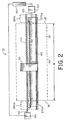
- printer apparatus for forming an image pixel 20 on a photosensitive media 30 in a manner that automatically avoids the need to write smaller pixels multiple times to produce pixels of larger size.
- photosensitive media 30 which has a marginal edge 35, a first side edge 37, a second side edge 38 and also a width "W", may be photosensitive paper or transparency.
- printer 10 comprises a print head 40, which is capable of being actuated to form image pixels 20 of various predetermined sizes on photosensitive media 30.
- Print head 40 includes a pair of coaxially aligned holes 45 therethrough (only one of which is shown), for reasons disclosed hereinbelow.
- print head 40 is attached to a carriage 50 that carries print head 40 relative to photosensitive media 30.
- carriage 50 traverses photosensitive media 30 so as to carry print head 40 in a first direction parallel with respect to marginal edge 35.
- Carriage 50 includes a first bore 52 therethrough lined with internal threads (not shown) and further includes a smooth second bore 55, for reasons disclosed hereinbelow.
- a support member or platen 60 is disposed near print head 40 for supporting photosensitive media 30 at a location adjacent print head 40.
- Platen 60 supports print head 40 in a manner such that photosensitive media 30 is interposed between print head 40 and platen 60 and such that photosensitive media 30 drapes platen 60, as shown.
- platen 60 and print head 40 define a gap 70 therebetween of predetermined width for accommodating photosensitive media 30 as photosensitive media 30 traverses through gap 70 in the manner disclosed more fully hereinbelow.
- nip roller 80 positioned adjacent platen 60 and anteriorly of print head 40 is an elongate photosensitive media nip roller 80. Nip roller 80 is disposed parallel to marginal edge 35.
- Nip roller 80 engages photosensitive media 30 for biasing photosensitive media 30 against platen 60 as photosensitive media 30 traverses through gap 70.
- a photosensitive media translation member such as a rotatable roller 90.
- Roller 90 is capable of intimately, engaging photosensitive media 30 for translating photosensitive media 30 through gap 70 in a direction perpendicular to the first direction traversed by carriage 50.
- a reversible first motor 100 engages an end portion of roller 90, such as by means of a first axle 105, so that photosensitive media 30 translates through gap 70 as first motor 100 rotates roller 90.
- First motor 100 is reversible for either advancing or retracting photosensitive media 30 through gap 70.
- a rotatable lead screw 110 disposed parallel to marginal edge 35 has exterior threads 140 thereon for threadably engaging the interior threads (not shown) lining first bore 52.
- a reversible second motor 130 engages an end portion of lead screw 110, such as by means of a second axle 120, so that carriage 50 translates along lead screw 110 as lead screw 110 rotates. Second motor 130 is reversible for reciprocatingly translating carriage 50 along lead screw 110 as lead screw 110 rotates in either a clock-wise or counter clock-wise direction. In this manner, carriage 50 and print head 40 translate parallel to marginal edge 35 of photosensitive media 30.
- Carriage 50 is itself slidably supported by a smooth elongate support rod 140 disposed parallel to marginal edge 35 and which matingly extends through smooth second bore 55. Thus, carriage 50 slides along support rod 140 and is supported thereby as carriage 50 translates parallel to marginal edge 35.
- a controller which may be a computer 160, is connected to carriage 50 for controlling movement of carriage 50, so that carriage 50 controllably translates print head 40 relative to photosensitive media 30.
- computer 160 is connected to first motor 100 and second motor 120 for controlling operation of first motor 100 and second motor 120, so that print head 40 is controllably carried by carriage 50.
- print head 40 comprises a light source, such as an LED ( L ight E mitting D iode) 170, for projecting a light beam 180 onto photosensitive media 30 to form image pixel 20 on photosensitive media 30.
- a light source such as an LED ( L ight E mitting D iode) 170
- the light source is a LED
- any suitable light source may be used, such as a laser.
- the light source is suitably modulated, by means (not shown) well known in the art, which modulation means synchronizes modulation of the light source to a raster image data source (also not shown). Such modulation results in the desired exposure of the raster image onto photosensitive media 30.
- an adjustable optical system is associated with LED 170 for adjustably sizing light beam 180.
- optical system 190 comprises an aperture system 200 disposed in print head 40 and interposed between LED 170 and photosensitive media 30.
- Aperture system 200 in turn includes a guide member 210 having a pair of parallel oppositely-facing grooves 220 therein for slidably receiving an aperture plate 230.
- Guide member 210 defines a opening 235 facing photosensitive media 30, for reasons disclosed hereinbelow.
- Aperture plate 230 has a first aperture 240 of a first size and a second aperture 250 of a second size spaced-apart from first aperture 240, but colinearly-aligned therewith along width "W" of photosensitive media 30.
- aperture plate 230 is slidable in grooves 220 from a first position thereof (see Fig. 3) for allowing light beam 180 to be received through first aperture 240 to a second position thereof (see Fig. 5) for allowing light beam 180 to be received through second aperture 250.
- first aperture 240 or second aperture 250 it will also pass through opening 235 to be intercepted by photosensitive media 30.
- Second image pixel size 260b is shown of larger size than first image pixel size 260a because second aperture 250 is larger than first aperture 240.
- an actuator assembly such as an elongate first actuator pin 270a and a colinearly aligned elongate second actuator pin 270b are provided for sliding aperture plate 230 in grooves 220.
- first actuator pin 270a is disposed a predetermined distance beyond the previously mentioned first side edge 37 of photosensitive media 30 and second actuator pin 270b is disposed a predetermined distance beyond the previously mentioned second side edge 38.
- Both first actuator pin 270a and second actuator pin 270b are sized to be matingly received through holes 45 in print head 40.
- first actuator pin 270a will engage aperture plate 230 to slide aperture plate 230 in grooves 220 to the second position thereof.
- second aperture 250 is aligned with light beam 180 for allowing light beam 180 to be received through second aperture 250.
- the size of the image pixel to be formed on photosensitive media 30 changes to image pixel size 260b because light beam 180 now passes through second aperture 250 rather than through first aperture 240.
- first actuator pin 270b will engage aperture plate 230 to slide aperture plate 230 in grooves 220 to the first position thereof.
- first aperture 240 is aligned with light beam 180 for allowing light beam 180 to be received through first aperture 240.
- the size of the image pixel to be formed on photosensitive media 30 changes to image pixel size 260a because light beam 180 now passes through first aperture 240 rather than through second aperture 250. It is appreciated that translating carriage 50 to first and second resolution changing locations 280a/280b beyond first and second side edges 37 and 38, respectively, avoids undesirable exposures on photosensitive media 30 during changing of image pixel resolutions.
- a light transmission conduit such as a fiber-optic cable 290
- a fiber-optic cable 290 may be interposed between LED 170 and aperture plate 230 for conducting and homogenizing light beam 180.
- Homogenizing light beam 180 tends to "scramble" the spatial intensity pattern of LED 170.
- fiber-optic cable 290 provides light beam 180 with an evenly illuminated radiance pattern as light beam 180 exits fiber optic cable 290.
- This feature of the present invention provides a uniform and well-defined image pixel 20.
- aperture system 200 may include a plurality of stops, such as posts 300, disposed adjacent guide member 210 and engageable with aperture plate 230, for terminating translation of aperture plate 230 as aperture plate 230 slides in grooves 220.
- lens 310 connected to print head 40 and interposed between aperture plate 230 and photosensitive media 30 is provided for focusing light beam 180 onto photosensitive media 30 in order to obtain a sharper and better defined image pixel 20.
- lens 310 may be selected to provide a 1:1 magnification ratio or other magnification ratio, as desired.
- an advantage of the present invention is image pixel resolutions or sizes may be automatically changed without requiring additional motors. This is so because carriage 50 is merely translated beyond first side edge 37 or second side edge 38 for engaging aperture plate 230 with first and second actuator pins 270a/270b, when desired.
- Another advantage of the present invention is that use thereof reduces printing time by avoiding the need to write smaller pixels multiple times to produce pixels of larger size. This so because aperture plate 230 is merely slid from one position thereof to another position thereof to allow light beam 180 to travel through a different size aperture.
- any suitable light source may be used to expose image pixels 20 on photosensitive media 30.
- a multiplicity of aperture sizes may be used to obtain a multiplicity of image pixel sizes.
- alternative means for sliding aperture plate 230 may be used, such as solenoids or motors dedicated to this purpose. However, use of solenoids or motors are not preferred because of increased costs due to purchase and assembly of such additional components.
Landscapes
- Printers Or Recording Devices Using Electromagnetic And Radiation Means (AREA)
- Projection-Type Copiers In General (AREA)
Applications Claiming Priority (2)
| Application Number | Priority Date | Filing Date | Title |
|---|---|---|---|
| US08/940,065 US6163332A (en) | 1997-09-29 | 1997-09-29 | Printer and method of forming multiple image pixel sizes on photosensitive media |
| US940065 | 1997-09-29 |
Publications (2)
| Publication Number | Publication Date |
|---|---|
| EP0904944A2 true EP0904944A2 (fr) | 1999-03-31 |
| EP0904944A3 EP0904944A3 (fr) | 1999-06-09 |
Family
ID=25474163
Family Applications (1)
| Application Number | Title | Priority Date | Filing Date |
|---|---|---|---|
| EP98203094A Withdrawn EP0904944A3 (fr) | 1997-09-29 | 1998-09-16 | Imprimante et méthode pour former de tailles multiples d'éléments d'image sur matériau photosensible |
Country Status (3)
| Country | Link |
|---|---|
| US (1) | US6163332A (fr) |
| EP (1) | EP0904944A3 (fr) |
| JP (1) | JPH11115244A (fr) |
Cited By (2)
| Publication number | Priority date | Publication date | Assignee | Title |
|---|---|---|---|---|
| EP2351648A2 (fr) * | 2008-10-14 | 2011-08-03 | Inktec Co., Ltd. | Système d'impression |
| CN104129170A (zh) * | 2014-08-15 | 2014-11-05 | 江苏申凯包装高新技术股份有限公司 | 可移动的打码装置 |
Families Citing this family (1)
| Publication number | Priority date | Publication date | Assignee | Title |
|---|---|---|---|---|
| US20050093965A1 (en) | 2003-11-04 | 2005-05-05 | Eastman Kodak Company | Multichannel printhead for photosensitive media |
Citations (1)
| Publication number | Priority date | Publication date | Assignee | Title |
|---|---|---|---|---|
| US4837589A (en) | 1987-10-23 | 1989-06-06 | Itek Graphix Corp. | Non-contact led-array image printer |
Family Cites Families (10)
| Publication number | Priority date | Publication date | Assignee | Title |
|---|---|---|---|---|
| FR2463433A1 (fr) * | 1979-08-14 | 1981-02-20 | Cit Alcatel | Dispositif de reproduction d'une image a densite variable de teinte |
| US4474422A (en) * | 1979-11-13 | 1984-10-02 | Canon Kabushiki Kaisha | Optical scanning apparatus having an array of light sources |
| US4841316A (en) * | 1988-02-17 | 1989-06-20 | The Gerber Scientific Instrument Company | Photohead system for positioning an aperture wheel and method of making an aperture disc |
| US5168288A (en) * | 1989-12-18 | 1992-12-01 | Eastman Kodak Company | Thermal a scan laser printer |
| US5434600A (en) * | 1990-06-25 | 1995-07-18 | Schoonscan, Inc. | Illumination module for bandwise imaging device |
| US5119113A (en) * | 1990-10-11 | 1992-06-02 | International Business Machines Corporation | Spot-defined exposure system for a laser printer |
| DE69222718T2 (de) * | 1991-08-23 | 1998-05-07 | Eastman Kodak Co | Laserdiodeträger mit Autofokusvorrichtung |
| US5311255A (en) * | 1993-05-04 | 1994-05-10 | Eastman Kodak Company | Real-time diagnostic system for detecting non-linear movement of an imaging member using optical fibers |
| US5745152A (en) * | 1994-10-31 | 1998-04-28 | Hewlett Packard Company | Multiple beam laser scanner using lasers with different aperture sizes |
| AU1065897A (en) * | 1995-12-05 | 1997-06-27 | Dicon A/S | A method and an apparatus for illuminating points on a photosensitive medium |
-
1997
- 1997-09-29 US US08/940,065 patent/US6163332A/en not_active Expired - Fee Related
-
1998
- 1998-08-18 JP JP23196498A patent/JPH11115244A/ja active Pending
- 1998-09-16 EP EP98203094A patent/EP0904944A3/fr not_active Withdrawn
Patent Citations (1)
| Publication number | Priority date | Publication date | Assignee | Title |
|---|---|---|---|---|
| US4837589A (en) | 1987-10-23 | 1989-06-06 | Itek Graphix Corp. | Non-contact led-array image printer |
Cited By (3)
| Publication number | Priority date | Publication date | Assignee | Title |
|---|---|---|---|---|
| EP2351648A2 (fr) * | 2008-10-14 | 2011-08-03 | Inktec Co., Ltd. | Système d'impression |
| EP2351648A4 (fr) * | 2008-10-14 | 2012-08-15 | Inktec Co Ltd | Système d'impression |
| CN104129170A (zh) * | 2014-08-15 | 2014-11-05 | 江苏申凯包装高新技术股份有限公司 | 可移动的打码装置 |
Also Published As
| Publication number | Publication date |
|---|---|
| EP0904944A3 (fr) | 1999-06-09 |
| US6163332A (en) | 2000-12-19 |
| JPH11115244A (ja) | 1999-04-27 |
Similar Documents
| Publication | Publication Date | Title |
|---|---|---|
| JP2930717B2 (ja) | サーマルプリンタ | |
| JP2990007B2 (ja) | 直接印刷タイプのポジリソグラフィック印刷プレートとこのプレートを形成する方法 | |
| EP1892576B1 (fr) | Dispositif d'éclairage destiné à la fabrication d'écrans de sérigraphie | |
| US7484827B2 (en) | Image forming method and apparatus, and a recording medium storing a program for performing an image forming method | |
| US6252241B1 (en) | Rotational scanning image recording system having both a large format and high resolution | |
| US6437849B1 (en) | Method and apparatus for printing on a photosensitive material using a liquid crystal display | |
| US5684620A (en) | High resolution imaging system and method of imaging using the same | |
| US6163332A (en) | Printer and method of forming multiple image pixel sizes on photosensitive media | |
| US5973717A (en) | Adjustable lead screw for changing resolution and for station-to-station, machine-to-machine, or swath-to-swath corrections | |
| US7164507B2 (en) | Image input terminal | |
| DE19728200C2 (de) | Abbildungssystem | |
| JP2813353B2 (ja) | 電子画像プリント装置 | |
| DE19728232A1 (de) | Verfahren und Vorrichtung zum Dehnen eines optischen Strahls in einem Abbildungssystem | |
| US4975714A (en) | Focusing mechanism for linescan imaging | |
| CN110892334B (zh) | 用于光敏聚合物印刷版的直接固化的系统和过程 | |
| US5146241A (en) | Automatic cut-out for auto-focus device | |
| DE602005004038T2 (de) | Druckgerät und verfahren | |
| US6222612B1 (en) | Process and device for the output of electronic image signals, and a photographic copier | |
| US5812175A (en) | Laser thermal printer with reversible imaging drum rotation for printing mirror images | |
| JPH0687097B2 (ja) | 受動的な反射面追跡型レーザ・ラスタ・スキャナ | |
| US20040041078A1 (en) | System and method for calibrating an imaging system during imaging | |
| US5633672A (en) | Real-time calibration of processless writer | |
| US5663554A (en) | Weak lens focus adjusting mechanism based upon thickness of scanned material and imagesetter using same | |
| US6264593B1 (en) | Punch assembly having a positive punch retraction mechanism for an internal drum imagesetter | |
| US6034713A (en) | Image processor having magnetically attached print head |
Legal Events
| Date | Code | Title | Description |
|---|---|---|---|
| PUAI | Public reference made under article 153(3) epc to a published international application that has entered the european phase |
Free format text: ORIGINAL CODE: 0009012 |
|
| AK | Designated contracting states |
Kind code of ref document: A2 Designated state(s): AT BE CH CY DE DK ES FI FR GB GR IE IT LI LU MC NL PT SE |
|
| AX | Request for extension of the european patent |
Free format text: AL;LT;LV;MK;RO;SI |
|
| PUAL | Search report despatched |
Free format text: ORIGINAL CODE: 0009013 |
|
| AK | Designated contracting states |
Kind code of ref document: A3 Designated state(s): AT BE CH CY DE DK ES FI FR GB GR IE IT LI LU MC NL PT SE |
|
| AX | Request for extension of the european patent |
Free format text: AL;LT;LV;MK;RO;SI |
|
| AKX | Designation fees paid | ||
| REG | Reference to a national code |
Ref country code: DE Ref legal event code: 8566 |
|
| STAA | Information on the status of an ep patent application or granted ep patent |
Free format text: STATUS: THE APPLICATION IS DEEMED TO BE WITHDRAWN |
|
| 18D | Application deemed to be withdrawn |
Effective date: 19991210 |