EP0904944A2 - Printer and method of forming multiple image pixel sizes on photosensitive media - Google Patents
Printer and method of forming multiple image pixel sizes on photosensitive media Download PDFInfo
- Publication number
- EP0904944A2 EP0904944A2 EP98203094A EP98203094A EP0904944A2 EP 0904944 A2 EP0904944 A2 EP 0904944A2 EP 98203094 A EP98203094 A EP 98203094A EP 98203094 A EP98203094 A EP 98203094A EP 0904944 A2 EP0904944 A2 EP 0904944A2
- Authority
- EP
- European Patent Office
- Prior art keywords
- aperture
- photosensitive media
- light beam
- light source
- image pixel
- Prior art date
- Legal status (The legal status is an assumption and is not a legal conclusion. Google has not performed a legal analysis and makes no representation as to the accuracy of the status listed.)
- Withdrawn
Links
- 238000000034 method Methods 0.000 title claims abstract description 14
- 238000004513 sizing Methods 0.000 claims abstract description 7
- 230000000873 masking effect Effects 0.000 claims abstract description 6
- 230000007723 transport mechanism Effects 0.000 abstract 2
- 230000032258 transport Effects 0.000 abstract 1
- 230000003287 optical effect Effects 0.000 description 7
- 230000002441 reversible effect Effects 0.000 description 5
- 238000013467 fragmentation Methods 0.000 description 4
- 238000006062 fragmentation reaction Methods 0.000 description 4
- 230000005540 biological transmission Effects 0.000 description 1
- 239000000835 fiber Substances 0.000 description 1
- 238000003384 imaging method Methods 0.000 description 1
- 238000012986 modification Methods 0.000 description 1
- 230000004048 modification Effects 0.000 description 1
- 239000000758 substrate Substances 0.000 description 1
Images


Classifications
-
- B—PERFORMING OPERATIONS; TRANSPORTING
- B41—PRINTING; LINING MACHINES; TYPEWRITERS; STAMPS
- B41J—TYPEWRITERS; SELECTIVE PRINTING MECHANISMS, i.e. MECHANISMS PRINTING OTHERWISE THAN FROM A FORME; CORRECTION OF TYPOGRAPHICAL ERRORS
- B41J19/00—Character- or line-spacing mechanisms
- B41J19/18—Character-spacing or back-spacing mechanisms; Carriage return or release devices therefor
- B41J19/20—Positive-feed character-spacing mechanisms
-
- B—PERFORMING OPERATIONS; TRANSPORTING
- B41—PRINTING; LINING MACHINES; TYPEWRITERS; STAMPS
- B41J—TYPEWRITERS; SELECTIVE PRINTING MECHANISMS, i.e. MECHANISMS PRINTING OTHERWISE THAN FROM A FORME; CORRECTION OF TYPOGRAPHICAL ERRORS
- B41J2/00—Typewriters or selective printing mechanisms characterised by the printing or marking process for which they are designed
- B41J2/435—Typewriters or selective printing mechanisms characterised by the printing or marking process for which they are designed characterised by selective application of radiation to a printing material or impression-transfer material
- B41J2/465—Typewriters or selective printing mechanisms characterised by the printing or marking process for which they are designed characterised by selective application of radiation to a printing material or impression-transfer material using masks, e.g. light-switching masks
Definitions
- This invention generally relates to printer apparatus and methods and more particularly relates to a printer apparatus and method of forming multiple image pixel sizes on photosensitive media.
- image pixels are formed on photosensitive media by means of optical energy (for example, a light beam).
- optical energy for example, a light beam
- One source of this optical energy may be a LED ( L ight E mitting D iode) housed in the print head, which may also house a focusing lens for focusing the optical energy onto the phtosensitive media.
- a carriage carrying the print head translates linearly along one dimension of the photosensitive media as the photosensitive media is held momentarily stationary beneath the print head, whereupon the print head prints one or more lines of image data on the photosensitive media. After one sweep of the carriage, the photosensitive media is advanced a predetermined distance and another sweep is performed to print another line of image data on the photosensitive media. By modulating the image data in synchronization with translation speed of the photosensitive media, a complete raster image is eventually printed or exposed onto the photosensitive media.
- a typical non-contact LED ( L ight E mitting D iode) array image printer is disclosed in US-A-4,837,589 titled "Non-Contact LED-Array Image Printer”.
- This patent discloses an LED array mounted on a substrate bearing an interface control circuit which receives video data through a ribbon cable.
- the LED array is imaged by a lens onto an exposure plane on a platen parallel to the direction of scanning.
- a photosensitive medium is driven in registration in forward and reverse directions biased against the exposure platen which defines the exposure plane.
- this device it appears that one limitation of this device is that it produces only one size of pixel. Therefore, in order to produce images of multiple pixel resolutions, it is necessary to write pixels of smaller size multiple times to produce larger pixels. This results in lowered printing speed.
- an object of the present invention is to provide an apparatus and method of forming multiple image pixel sizes on photosensitive media, which apparatus and method avoid the need to write smaller pixels multiple times to produce pixels of larger size.
- the present invention resides in a printer for forming multiple image pixel sizes on a photosensitive media, characterized by: a light source for projecting a light beam onto the photosensitive media to form the multiple image pixel sizes on the photosensitive media; and an aperture system interposed between said light source and the photosensitive media for adjustably sizing the light beam, said aperture system including an adjustable aperture plate for receiving the light beam therethrough, said aperture plate being adjustable for variably masking a predetermined portion of the light beam, so that the multiple image pixel sizes are formed on the photosensitive media as the predetermined portion of the light beam is masked.
- the printer comprises a light source for projecting a light beam onto the photosensitive media to form the image pixel on the photosensitive media.
- An aperture system is interposed between the light source and the photosensitive media for adjustably sizing the light beam, the aperture system comprising an aperture plate having a plurality of optical apertures for receiving the light beam therethrough.
- the aperture plate is adjustable for variably masking a predetermined portion of the light beam, so that the image pixel obtains a predetermined size as the predetermined portion of the light beam is masked.
- the aperture system also includes a guide member having parallel oppositely-faced grooves therein.
- the aperture plate which slidably engages the grooves, has a first aperture of a first size and a second aperture of a second size spaced-apart from the first aperture.
- the aperture plate is slidable in the grooves from a first position thereof for allowing the light beam to be received through the first aperture.
- a predetermined first image pixel size is formed on the photosensitive media.
- the aperture plate is also slidable to a second position thereof for allowing the light beam to be received through the second aperture.
- a predetermined second image pixel size is formed on the photosensitive media.
- An actuator is engageable with the aperture plate for moving the aperture plate, so that the desired aperture size is selected.
- a carriage interconnecting the light source and the aperture system is also provided for carrying the light source and the aperture system relative to the photosensitive media for forming the image pixels on the photosensitive media.
- a controller-motor mechanism is connected to the carriage for controllably translating the carriage, so that the carriage controllably carries the light source and the aperture system relative to the photosensitive media.
- the light source may be an LED ( L ight E mitting D iode) with a fiber-optic cable interposed between the LED and the photosensitive media for conducting the light beam from the LED to the photosensitive media with minimal energy loss.
- a feature of the present invention is the provision of an aperture system interposed between the light source and the photosensitive media for adjustably sizing the light beam by masking a predetermined portion of the light beam, so that the light beam forms an image pixel of predetermined size.
- An advantage of the present invention is image pixel sizes may be automatically changed without requiring additional motors.
- Another advantage of the present invention is that use thereof reduces printing time.
- printer apparatus for forming an image pixel 20 on a photosensitive media 30 in a manner that automatically avoids the need to write smaller pixels multiple times to produce pixels of larger size.
- photosensitive media 30 which has a marginal edge 35, a first side edge 37, a second side edge 38 and also a width "W", may be photosensitive paper or transparency.
- printer 10 comprises a print head 40, which is capable of being actuated to form image pixels 20 of various predetermined sizes on photosensitive media 30.
- Print head 40 includes a pair of coaxially aligned holes 45 therethrough (only one of which is shown), for reasons disclosed hereinbelow.
- print head 40 is attached to a carriage 50 that carries print head 40 relative to photosensitive media 30.
- carriage 50 traverses photosensitive media 30 so as to carry print head 40 in a first direction parallel with respect to marginal edge 35.
- Carriage 50 includes a first bore 52 therethrough lined with internal threads (not shown) and further includes a smooth second bore 55, for reasons disclosed hereinbelow.
- a support member or platen 60 is disposed near print head 40 for supporting photosensitive media 30 at a location adjacent print head 40.
- Platen 60 supports print head 40 in a manner such that photosensitive media 30 is interposed between print head 40 and platen 60 and such that photosensitive media 30 drapes platen 60, as shown.
- platen 60 and print head 40 define a gap 70 therebetween of predetermined width for accommodating photosensitive media 30 as photosensitive media 30 traverses through gap 70 in the manner disclosed more fully hereinbelow.
- nip roller 80 positioned adjacent platen 60 and anteriorly of print head 40 is an elongate photosensitive media nip roller 80. Nip roller 80 is disposed parallel to marginal edge 35.
- Nip roller 80 engages photosensitive media 30 for biasing photosensitive media 30 against platen 60 as photosensitive media 30 traverses through gap 70.
- a photosensitive media translation member such as a rotatable roller 90.
- Roller 90 is capable of intimately, engaging photosensitive media 30 for translating photosensitive media 30 through gap 70 in a direction perpendicular to the first direction traversed by carriage 50.
- a reversible first motor 100 engages an end portion of roller 90, such as by means of a first axle 105, so that photosensitive media 30 translates through gap 70 as first motor 100 rotates roller 90.
- First motor 100 is reversible for either advancing or retracting photosensitive media 30 through gap 70.
- a rotatable lead screw 110 disposed parallel to marginal edge 35 has exterior threads 140 thereon for threadably engaging the interior threads (not shown) lining first bore 52.
- a reversible second motor 130 engages an end portion of lead screw 110, such as by means of a second axle 120, so that carriage 50 translates along lead screw 110 as lead screw 110 rotates. Second motor 130 is reversible for reciprocatingly translating carriage 50 along lead screw 110 as lead screw 110 rotates in either a clock-wise or counter clock-wise direction. In this manner, carriage 50 and print head 40 translate parallel to marginal edge 35 of photosensitive media 30.
- Carriage 50 is itself slidably supported by a smooth elongate support rod 140 disposed parallel to marginal edge 35 and which matingly extends through smooth second bore 55. Thus, carriage 50 slides along support rod 140 and is supported thereby as carriage 50 translates parallel to marginal edge 35.
- a controller which may be a computer 160, is connected to carriage 50 for controlling movement of carriage 50, so that carriage 50 controllably translates print head 40 relative to photosensitive media 30.
- computer 160 is connected to first motor 100 and second motor 120 for controlling operation of first motor 100 and second motor 120, so that print head 40 is controllably carried by carriage 50.
- print head 40 comprises a light source, such as an LED ( L ight E mitting D iode) 170, for projecting a light beam 180 onto photosensitive media 30 to form image pixel 20 on photosensitive media 30.
- a light source such as an LED ( L ight E mitting D iode) 170
- the light source is a LED
- any suitable light source may be used, such as a laser.
- the light source is suitably modulated, by means (not shown) well known in the art, which modulation means synchronizes modulation of the light source to a raster image data source (also not shown). Such modulation results in the desired exposure of the raster image onto photosensitive media 30.
- an adjustable optical system is associated with LED 170 for adjustably sizing light beam 180.
- optical system 190 comprises an aperture system 200 disposed in print head 40 and interposed between LED 170 and photosensitive media 30.
- Aperture system 200 in turn includes a guide member 210 having a pair of parallel oppositely-facing grooves 220 therein for slidably receiving an aperture plate 230.
- Guide member 210 defines a opening 235 facing photosensitive media 30, for reasons disclosed hereinbelow.
- Aperture plate 230 has a first aperture 240 of a first size and a second aperture 250 of a second size spaced-apart from first aperture 240, but colinearly-aligned therewith along width "W" of photosensitive media 30.
- aperture plate 230 is slidable in grooves 220 from a first position thereof (see Fig. 3) for allowing light beam 180 to be received through first aperture 240 to a second position thereof (see Fig. 5) for allowing light beam 180 to be received through second aperture 250.
- first aperture 240 or second aperture 250 it will also pass through opening 235 to be intercepted by photosensitive media 30.
- Second image pixel size 260b is shown of larger size than first image pixel size 260a because second aperture 250 is larger than first aperture 240.
- an actuator assembly such as an elongate first actuator pin 270a and a colinearly aligned elongate second actuator pin 270b are provided for sliding aperture plate 230 in grooves 220.
- first actuator pin 270a is disposed a predetermined distance beyond the previously mentioned first side edge 37 of photosensitive media 30 and second actuator pin 270b is disposed a predetermined distance beyond the previously mentioned second side edge 38.
- Both first actuator pin 270a and second actuator pin 270b are sized to be matingly received through holes 45 in print head 40.
- first actuator pin 270a will engage aperture plate 230 to slide aperture plate 230 in grooves 220 to the second position thereof.
- second aperture 250 is aligned with light beam 180 for allowing light beam 180 to be received through second aperture 250.
- the size of the image pixel to be formed on photosensitive media 30 changes to image pixel size 260b because light beam 180 now passes through second aperture 250 rather than through first aperture 240.
- first actuator pin 270b will engage aperture plate 230 to slide aperture plate 230 in grooves 220 to the first position thereof.
- first aperture 240 is aligned with light beam 180 for allowing light beam 180 to be received through first aperture 240.
- the size of the image pixel to be formed on photosensitive media 30 changes to image pixel size 260a because light beam 180 now passes through first aperture 240 rather than through second aperture 250. It is appreciated that translating carriage 50 to first and second resolution changing locations 280a/280b beyond first and second side edges 37 and 38, respectively, avoids undesirable exposures on photosensitive media 30 during changing of image pixel resolutions.
- a light transmission conduit such as a fiber-optic cable 290
- a fiber-optic cable 290 may be interposed between LED 170 and aperture plate 230 for conducting and homogenizing light beam 180.
- Homogenizing light beam 180 tends to "scramble" the spatial intensity pattern of LED 170.
- fiber-optic cable 290 provides light beam 180 with an evenly illuminated radiance pattern as light beam 180 exits fiber optic cable 290.
- This feature of the present invention provides a uniform and well-defined image pixel 20.
- aperture system 200 may include a plurality of stops, such as posts 300, disposed adjacent guide member 210 and engageable with aperture plate 230, for terminating translation of aperture plate 230 as aperture plate 230 slides in grooves 220.
- lens 310 connected to print head 40 and interposed between aperture plate 230 and photosensitive media 30 is provided for focusing light beam 180 onto photosensitive media 30 in order to obtain a sharper and better defined image pixel 20.
- lens 310 may be selected to provide a 1:1 magnification ratio or other magnification ratio, as desired.
- an advantage of the present invention is image pixel resolutions or sizes may be automatically changed without requiring additional motors. This is so because carriage 50 is merely translated beyond first side edge 37 or second side edge 38 for engaging aperture plate 230 with first and second actuator pins 270a/270b, when desired.
- Another advantage of the present invention is that use thereof reduces printing time by avoiding the need to write smaller pixels multiple times to produce pixels of larger size. This so because aperture plate 230 is merely slid from one position thereof to another position thereof to allow light beam 180 to travel through a different size aperture.
- any suitable light source may be used to expose image pixels 20 on photosensitive media 30.
- a multiplicity of aperture sizes may be used to obtain a multiplicity of image pixel sizes.
- alternative means for sliding aperture plate 230 may be used, such as solenoids or motors dedicated to this purpose. However, use of solenoids or motors are not preferred because of increased costs due to purchase and assembly of such additional components.
Landscapes
- Printers Or Recording Devices Using Electromagnetic And Radiation Means (AREA)
- Projection-Type Copiers In General (AREA)
Abstract
Description
- This invention generally relates to printer apparatus and methods and more particularly relates to a printer apparatus and method of forming multiple image pixel sizes on photosensitive media.
- In some prior art printers, image pixels are formed on photosensitive media by means of optical energy (for example, a light beam). One source of this optical energy may be a LED (Light Emitting Diode) housed in the print head, which may also house a focusing lens for focusing the optical energy onto the phtosensitive media. A carriage carrying the print head translates linearly along one dimension of the photosensitive media as the photosensitive media is held momentarily stationary beneath the print head, whereupon the print head prints one or more lines of image data on the photosensitive media. After one sweep of the carriage, the photosensitive media is advanced a predetermined distance and another sweep is performed to print another line of image data on the photosensitive media. By modulating the image data in synchronization with translation speed of the photosensitive media, a complete raster image is eventually printed or exposed onto the photosensitive media.
- A typical non-contact LED (Light Emitting Diode) array image printer is disclosed in US-A-4,837,589 titled "Non-Contact LED-Array Image Printer". This patent discloses an LED array mounted on a substrate bearing an interface control circuit which receives video data through a ribbon cable. The LED array is imaged by a lens onto an exposure plane on a platen parallel to the direction of scanning. A photosensitive medium is driven in registration in forward and reverse directions biased against the exposure platen which defines the exposure plane. However, it appears that one limitation of this device is that it produces only one size of pixel. Therefore, in order to produce images of multiple pixel resolutions, it is necessary to write pixels of smaller size multiple times to produce larger pixels. This results in lowered printing speed.
- Therefore, an object of the present invention is to provide an apparatus and method of forming multiple image pixel sizes on photosensitive media, which apparatus and method avoid the need to write smaller pixels multiple times to produce pixels of larger size.
- The present invention resides in a printer for forming multiple image pixel sizes on a photosensitive media, characterized by: a light source for projecting a light beam onto the photosensitive media to form the multiple image pixel sizes on the photosensitive media; and an aperture system interposed between said light source and the photosensitive media for adjustably sizing the light beam, said aperture system including an adjustable aperture plate for receiving the light beam therethrough, said aperture plate being adjustable for variably masking a predetermined portion of the light beam, so that the multiple image pixel sizes are formed on the photosensitive media as the predetermined portion of the light beam is masked.
- According to one aspect of the invention the printer comprises a light source for projecting a light beam onto the photosensitive media to form the image pixel on the photosensitive media. An aperture system is interposed between the light source and the photosensitive media for adjustably sizing the light beam, the aperture system comprising an aperture plate having a plurality of optical apertures for receiving the light beam therethrough. The aperture plate is adjustable for variably masking a predetermined portion of the light beam, so that the image pixel obtains a predetermined size as the predetermined portion of the light beam is masked. More specifically, the aperture system also includes a guide member having parallel oppositely-faced grooves therein. The aperture plate, which slidably engages the grooves, has a first aperture of a first size and a second aperture of a second size spaced-apart from the first aperture. The aperture plate is slidable in the grooves from a first position thereof for allowing the light beam to be received through the first aperture. As the light beam is received through the first aperture, a predetermined first image pixel size is formed on the photosensitive media. The aperture plate is also slidable to a second position thereof for allowing the light beam to be received through the second aperture. As the light beam is received through the second aperture, a predetermined second image pixel size is formed on the photosensitive media. An actuator is engageable with the aperture plate for moving the aperture plate, so that the desired aperture size is selected. Moreover, a carriage interconnecting the light source and the aperture system is also provided for carrying the light source and the aperture system relative to the photosensitive media for forming the image pixels on the photosensitive media. In addition, a controller-motor mechanism is connected to the carriage for controllably translating the carriage, so that the carriage controllably carries the light source and the aperture system relative to the photosensitive media. The light source may be an LED (Light Emitting Diode) with a fiber-optic cable interposed between the LED and the photosensitive media for conducting the light beam from the LED to the photosensitive media with minimal energy loss.
- A feature of the present invention is the provision of an aperture system interposed between the light source and the photosensitive media for adjustably sizing the light beam by masking a predetermined portion of the light beam, so that the light beam forms an image pixel of predetermined size.
- An advantage of the present invention is image pixel sizes may be automatically changed without requiring additional motors.
- Another advantage of the present invention is that use thereof reduces printing time.
- These and other objects, features and advantages of the present invention will become apparent to those skilled in the art upon a reading of the following detailed description when taken in conjunction with the drawings wherein there is shown and described illustrative embodiments of the invention.
- While the specification concludes with claims particularly pointing-out and distinctly claiming the subject matter of the present invention, it is believed the invention will be better understood from the following description when taken in conjunction with the accompanying drawings wherein:
- Figure 1 is a view in perspective of a printer apparatus, with parts removed for clarity;
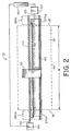
- Figure 2 is a plan view of the printer apparatus;
- Figure 3 is a fragmentation view in perspective of a print head belonging to the printer apparatus, the print head shown forming an image pixel of a first predetermined size on a photosensitive media;
- Figure 4 is a fragmentation view in perspective of the print head disposed in a first resolution changing location beyond a first side edge of the photosensitive media prior to being translated to the photosensitive media in order to form an image pixel of a second predetermined size;
- Figure 5 is fragmentation view in perspective of the print head forming the image pixel of the second predetermined size on the photosensitive media; and
- Figure 6 is a fragmentation view in perspective of the print head disposed in a second resolution changing location beyond a second side edge of the photosensitive media prior to being translated to the photosensitive media in order to form the image pixel of the first predetermined size.
-
- The present description will be directed in particular to elements forming part of, or cooperating more directly with, apparatus in accordance with the present invention. It is to be understood that elements not specifically shown or described may take various forms well known to those skilled in the art.
- Therefore, referring to Figs. 1, 2 and 3, there is shown a printer apparatus, generally referred to as 10, for forming an
image pixel 20 on aphotosensitive media 30 in a manner that automatically avoids the need to write smaller pixels multiple times to produce pixels of larger size. In this regard,photosensitive media 30, which has amarginal edge 35, afirst side edge 37, asecond side edge 38 and also a width "W", may be photosensitive paper or transparency. As described more fully hereinbelow,printer 10 comprises aprint head 40, which is capable of being actuated to formimage pixels 20 of various predetermined sizes onphotosensitive media 30.Print head 40 includes a pair of coaxially alignedholes 45 therethrough (only one of which is shown), for reasons disclosed hereinbelow. In addition,print head 40 is attached to acarriage 50 that carriesprint head 40 relative tophotosensitive media 30. As described more fully hereinbelow,carriage 50 traversesphotosensitive media 30 so as to carryprint head 40 in a first direction parallel with respect tomarginal edge 35. Carriage 50 includes afirst bore 52 therethrough lined with internal threads (not shown) and further includes a smoothsecond bore 55, for reasons disclosed hereinbelow. - Referring again to Figs. 1, 2 and 3, a support member or
platen 60 is disposed nearprint head 40 for supportingphotosensitive media 30 at a locationadjacent print head 40.Platen 60 supportsprint head 40 in a manner such thatphotosensitive media 30 is interposed betweenprint head 40 andplaten 60 and such thatphotosensitive media 30drapes platen 60, as shown. In this regard,platen 60 andprint head 40 define agap 70 therebetween of predetermined width for accommodatingphotosensitive media 30 asphotosensitive media 30 traverses throughgap 70 in the manner disclosed more fully hereinbelow. In addition, positionedadjacent platen 60 and anteriorly ofprint head 40 is an elongate photosensitivemedia nip roller 80.Nip roller 80 is disposed parallel tomarginal edge 35. Niproller 80 engagesphotosensitive media 30 for biasingphotosensitive media 30 againstplaten 60 asphotosensitive media 30 traverses throughgap 70. Moreover, also disposedadjacent platen 60 is a photosensitive media translation member, such as a rotatable roller 90. Roller 90 is capable of intimately, engagingphotosensitive media 30 for translatingphotosensitive media 30 throughgap 70 in a direction perpendicular to the first direction traversed bycarriage 50. More specifically, a reversiblefirst motor 100 engages an end portion of roller 90, such as by means of afirst axle 105, so thatphotosensitive media 30 translates throughgap 70 asfirst motor 100 rotates roller 90.First motor 100 is reversible for either advancing or retractingphotosensitive media 30 throughgap 70. In addition, arotatable lead screw 110 disposed parallel tomarginal edge 35 hasexterior threads 140 thereon for threadably engaging the interior threads (not shown) lining firstbore 52. A reversiblesecond motor 130 engages an end portion oflead screw 110, such as by means of asecond axle 120, so thatcarriage 50 translates alonglead screw 110 aslead screw 110 rotates.Second motor 130 is reversible for reciprocatingly translatingcarriage 50 alonglead screw 110 aslead screw 110 rotates in either a clock-wise or counter clock-wise direction. In this manner,carriage 50 andprint head 40 translate parallel tomarginal edge 35 ofphotosensitive media 30.Carriage 50 is itself slidably supported by a smoothelongate support rod 140 disposed parallel tomarginal edge 35 and which matingly extends through smoothsecond bore 55. Thus,carriage 50 slides alongsupport rod 140 and is supported thereby ascarriage 50 translates parallel tomarginal edge 35. In addition, a controller, which may be acomputer 160, is connected tocarriage 50 for controlling movement ofcarriage 50, so thatcarriage 50 controllably translatesprint head 40 relative tophotosensitive media 30. In this regard,computer 160 is connected tofirst motor 100 andsecond motor 120 for controlling operation offirst motor 100 andsecond motor 120, so thatprint head 40 is controllably carried bycarriage 50. - Referring now to Figs. 3, 4 and 5,
print head 40 comprises a light source, such as an LED (Light Emitting Diode) 170, for projecting alight beam 180 ontophotosensitive media 30 to formimage pixel 20 onphotosensitive media 30. Although in the preferred embodiment of the present invention, the light source is a LED, any suitable light source may be used, such as a laser. The light source is suitably modulated, by means (not shown) well known in the art, which modulation means synchronizes modulation of the light source to a raster image data source (also not shown). Such modulation results in the desired exposure of the raster image ontophotosensitive media 30. - Referring again to Figs. 3, 4 and 5, an adjustable optical system, generally referred to as 190, is associated with
LED 170 for adjustably sizinglight beam 180. More specifically,optical system 190 comprises anaperture system 200 disposed inprint head 40 and interposed betweenLED 170 andphotosensitive media 30.Aperture system 200 in turn includes aguide member 210 having a pair of parallel oppositely-facinggrooves 220 therein for slidably receiving anaperture plate 230.Guide member 210 defines aopening 235 facingphotosensitive media 30, for reasons disclosed hereinbelow.Aperture plate 230 has afirst aperture 240 of a first size and asecond aperture 250 of a second size spaced-apart fromfirst aperture 240, but colinearly-aligned therewith along width "W" ofphotosensitive media 30. As described more fully hereinbelow,aperture plate 230 is slidable ingrooves 220 from a first position thereof (see Fig. 3) for allowinglight beam 180 to be received throughfirst aperture 240 to a second position thereof (see Fig. 5) for allowinglight beam 180 to be received throughsecond aperture 250. Of course, aslight beam 180 passes through eitherfirst aperture 240 orsecond aperture 250, it will also pass through opening 235 to be intercepted byphotosensitive media 30. It is appreciated from the description hereinabove that, aslight beam 180 is received throughfirst aperture 240 andopening 235,light beam 180 will predetermine a firstimage pixel size 260a (see Fig. 3) and aslight beam 180 is received throughsecond aperture 250 andopening 235,light beam 180 will predetermine a second image pixel size 260b different than firstimage pixel size 260a (see Fig. 5). Second image pixel size 260b is shown of larger size than firstimage pixel size 260a becausesecond aperture 250 is larger thanfirst aperture 240. - Referring to Figs. 2, 4 and 6, an actuator assembly, such as an elongate
first actuator pin 270a and a colinearly aligned elongatesecond actuator pin 270b are provided for slidingaperture plate 230 ingrooves 220. For reasons described in more detail presently,first actuator pin 270a is disposed a predetermined distance beyond the previously mentionedfirst side edge 37 ofphotosensitive media 30 andsecond actuator pin 270b is disposed a predetermined distance beyond the previously mentionedsecond side edge 38. Bothfirst actuator pin 270a andsecond actuator pin 270b are sized to be matingly received throughholes 45 inprint head 40. Thus, aslead screw 110 translatescarriage 50 to a firstresolution changing location 280a beyondfirst side edge 37,first actuator pin 270a will engageaperture plate 230 to slideaperture plate 230 ingrooves 220 to the second position thereof. When the second position ofaperture plate 230 is reached,second aperture 250 is aligned withlight beam 180 for allowinglight beam 180 to be received throughsecond aperture 250. In this manner, the size of the image pixel to be formed onphotosensitive media 30 changes to image pixel size 260b becauselight beam 180 now passes throughsecond aperture 250 rather than throughfirst aperture 240. Moreover, aslead screw 110 translatescarriage 50 to a secondresolution changing location 280b beyondsecond side edge 38,second actuator pin 270b will engageaperture plate 230 to slideaperture plate 230 ingrooves 220 to the first position thereof. When the first position ofaperture plate 230 is reached,first aperture 240 is aligned withlight beam 180 for allowinglight beam 180 to be received throughfirst aperture 240. In this manner, the size of the image pixel to be formed onphotosensitive media 30 changes to imagepixel size 260a becauselight beam 180 now passes throughfirst aperture 240 rather than throughsecond aperture 250. It is appreciated that translatingcarriage 50 to first and secondresolution changing locations 280a/280b beyond first and second side edges 37 and 38, respectively, avoids undesirable exposures onphotosensitive media 30 during changing of image pixel resolutions. This is so becauselight beam 180 is not intercepted byphotosensitive media 30 whencarriage 50 is disposed in either firstresolution changing location 280a or secondresolution changing location 280b. Moreover, it is appreciated that once a resolution (that is, image pixel size) is selected for imaging onphotosensitive media 30, it is not necessary to translatecarriage 50 beyond first and second side edges 37/38. That is,carriage 50 is controlled such that an entire raster image comprising a multiplicity ofimage pixels 20 may be exposed ontophotosensitive media 30 at the selected resolution withoutcarriage 50 translating beyond width "W". - Referring to Figs. 3, 4, 5 and 6, a light transmission conduit, such as a fiber-
optic cable 290, may be interposed betweenLED 170 andaperture plate 230 for conducting and homogenizinglight beam 180. Homogenizinglight beam 180 tends to "scramble" the spatial intensity pattern ofLED 170. Thus, fiber-optic cable 290 provideslight beam 180 with an evenly illuminated radiance pattern aslight beam 180 exitsfiber optic cable 290. This feature of the present invention provides a uniform and well-definedimage pixel 20. In addition,aperture system 200 may include a plurality of stops, such asposts 300, disposedadjacent guide member 210 and engageable withaperture plate 230, for terminating translation ofaperture plate 230 asaperture plate 230 slides ingrooves 220. This feature of the present invention ensures thataperture plate 230 will always remain ingrooves 220. Moreover, an opticallytransparent lens 310 connected to printhead 40 and interposed betweenaperture plate 230 andphotosensitive media 30 is provided for focusinglight beam 180 ontophotosensitive media 30 in order to obtain a sharper and better definedimage pixel 20. In addition,lens 310 may be selected to provide a 1:1 magnification ratio or other magnification ratio, as desired. - It is understood from the teachings herein that an advantage of the present invention is image pixel resolutions or sizes may be automatically changed without requiring additional motors. This is so because
carriage 50 is merely translated beyondfirst side edge 37 orsecond side edge 38 for engagingaperture plate 230 with first andsecond actuator pins 270a/270b, when desired. Another advantage of the present invention is that use thereof reduces printing time by avoiding the need to write smaller pixels multiple times to produce pixels of larger size. This so becauseaperture plate 230 is merely slid from one position thereof to another position thereof to allowlight beam 180 to travel through a different size aperture. - The invention has been described in detail with particular reference to certain preferred embodiments thereof, but it will be understood that variations and modifications can be effected within the spirit and scope of the invention. For example, any suitable light source may be used to expose
image pixels 20 onphotosensitive media 30. As another example, a multiplicity of aperture sizes may be used to obtain a multiplicity of image pixel sizes. As yet another example, alternative means for slidingaperture plate 230 may be used, such as solenoids or motors dedicated to this purpose. However, use of solenoids or motors are not preferred because of increased costs due to purchase and assembly of such additional components. - Therefore, what is provided are an apparatus and method of forming multiple image pixel sizes on photosensitive media, which apparatus and method avoid the need to write smaller pixels multiple times to produce pixels of larger size.
-
- 10
- printer apparatus
- 20
- image pixel
- 30
- photosensitive media
- 35
- marginal edge
- 37
- first side edge
- 38
- second side edge
- 40
- print head
- 45
- hole
- 50
- carriage
- 52
- first bore
- 55
- second bore
- 60
- platen
- 70
- gap
- 80
- photosensitive media nip roller
- 90
- roller
- 100
- first motor
- 105
- first axle
- 110
- lead screw
- 120
- second axle
- 130
- second motor
- 140
- support rod
- 160
- computer
- 170
- LED
- 180
- light beam
- 190
- optical system
- 200
- aperture system
- 210
- guide member
- 220
- grooves
- 230
- aperture plate
- 235
- opening
- 240
- first aperture
- 250
- second aperture
- 260a
- first image pixel size
- 260b
- second image pixel size
- 270a
- first actuator pin
- 270b
- second actuator pin
- 280a
- first resolution changing location
- 280b
- second resolution changing location
- 290
- fiber-optic cable
- 300
- posts
- 310
- lens
Claims (12)
- A printer for forming multiple image pixel sizes on a photosensitive media (30), characterized by:(a) a light source (170) for projecting a light beam (180) onto the photosensitive media to form the multiple image pixel sizes on the photosensitive media; and(b) an aperture system (200) interposed between said light source and the photosensitive media for adjustably sizing the light beam, said aperture system including an adjustable aperture plate (230) for receiving the light beam therethrough, said aperture plate being adjustable for variably masking a predetermined portion of the light beam, so that the multiple image pixel sizes are formed on the photosensitive media as the predetermined portion of the light beam is masked.
- The printer of claim 1, further characterized by an actuator (270a/b) engageable with said aperture system for actuating said aperture system, so that said aperture plate is adjusted thereby.
- The printer of claim 1, further characterized by a carriage (50) interconnecting said light source and said aperture system for carrying said light source and said aperture system relative to the photosensitive media.
- The printer of claim 1, further characterized by a controller (160) connected to said carriage for controlling said carriage, so that said carriage controllably carries said light source and said aperture system relative to the photosensitive media.
- The printer of claim 1, wherein said light source is a light emitting diode.
- The printer of claim 1, further characterized by a fiber-optic conduit (290) interposed between said light source and the photosensitive media for conducting the light beam from said light source to the photosensitive media.
- A method of providing a printer capable of forming multiple image pixel sizes on a photosensitive media (30), characterized by the steps of:(a) providing a light source (170) for projecting a light beam (180) onto the photosensitive media to form the multiple image pixel sizes on the photosensitive media; and(b) providing an aperture system (200) interposed between the light source and the photosensitive media for adjustably sizing the light beam, the aperture system including an adjustable aperture plate (230) for receiving the light beam therethrough, the aperture plate being adjustable for variably masking a predetermined portion of the light beam, so that the multiple image pixel sizes form as the predetermined portion of the light beam is masked.
- The method of claim 7, further characterized by the step of providing an actuator (270a/b) engageable with the aperture system for actuating the aperture system, so that the aperture plate is adjusted thereby.
- The method of claim 7, further characterized by the step of providing a carriage (50) interconnecting the light source and the aperture system for carrying the light source and the aperture system relative to the photosensitive media.
- The method of claim 9, further characterized by the step of providing a controller (160) connected to the carriage for controlling the carriage, so that the carriage controllably carries the light source and the aperture system relative to the photosensitive media.
- The method of claim 7, wherein the step of providing a light source is characterized by the step of providing a light emitting diode.
- The method of claim 7, further characterized by the step of providing a fiber-optic conduit (290) interposed between the light source and the photosensitive media for conducting the light beam from the light source to the photosensitive media.
Applications Claiming Priority (2)
| Application Number | Priority Date | Filing Date | Title |
|---|---|---|---|
| US08/940,065 US6163332A (en) | 1997-09-29 | 1997-09-29 | Printer and method of forming multiple image pixel sizes on photosensitive media |
| US940065 | 1997-09-29 |
Publications (2)
| Publication Number | Publication Date |
|---|---|
| EP0904944A2 true EP0904944A2 (en) | 1999-03-31 |
| EP0904944A3 EP0904944A3 (en) | 1999-06-09 |
Family
ID=25474163
Family Applications (1)
| Application Number | Title | Priority Date | Filing Date |
|---|---|---|---|
| EP98203094A Withdrawn EP0904944A3 (en) | 1997-09-29 | 1998-09-16 | Printer and method of forming multiple image pixel sizes on photosensitive media |
Country Status (3)
| Country | Link |
|---|---|
| US (1) | US6163332A (en) |
| EP (1) | EP0904944A3 (en) |
| JP (1) | JPH11115244A (en) |
Cited By (2)
| Publication number | Priority date | Publication date | Assignee | Title |
|---|---|---|---|---|
| EP2351648A4 (en) * | 2008-10-14 | 2012-08-15 | Inktec Co Ltd | PRESSURE SYSTEM |
| CN104129170A (en) * | 2014-08-15 | 2014-11-05 | 江苏申凯包装高新技术股份有限公司 | Movable code printing device |
Families Citing this family (1)
| Publication number | Priority date | Publication date | Assignee | Title |
|---|---|---|---|---|
| US20050093965A1 (en) * | 2003-11-04 | 2005-05-05 | Eastman Kodak Company | Multichannel printhead for photosensitive media |
Citations (1)
| Publication number | Priority date | Publication date | Assignee | Title |
|---|---|---|---|---|
| US4837589A (en) | 1987-10-23 | 1989-06-06 | Itek Graphix Corp. | Non-contact led-array image printer |
Family Cites Families (10)
| Publication number | Priority date | Publication date | Assignee | Title |
|---|---|---|---|---|
| FR2463433A1 (en) * | 1979-08-14 | 1981-02-20 | Cit Alcatel | DEVICE FOR REPRODUCING A VARIABLE DENSITY IMAGE OF HUE |
| US4474422A (en) * | 1979-11-13 | 1984-10-02 | Canon Kabushiki Kaisha | Optical scanning apparatus having an array of light sources |
| US4841316A (en) * | 1988-02-17 | 1989-06-20 | The Gerber Scientific Instrument Company | Photohead system for positioning an aperture wheel and method of making an aperture disc |
| US5168288A (en) * | 1989-12-18 | 1992-12-01 | Eastman Kodak Company | Thermal a scan laser printer |
| US5434600A (en) * | 1990-06-25 | 1995-07-18 | Schoonscan, Inc. | Illumination module for bandwise imaging device |
| US5119113A (en) * | 1990-10-11 | 1992-06-02 | International Business Machines Corporation | Spot-defined exposure system for a laser printer |
| EP0529561B1 (en) * | 1991-08-23 | 1997-10-15 | Eastman Kodak Company | Laser diode mount and auto-focus means |
| US5311255A (en) * | 1993-05-04 | 1994-05-10 | Eastman Kodak Company | Real-time diagnostic system for detecting non-linear movement of an imaging member using optical fibers |
| US5745152A (en) * | 1994-10-31 | 1998-04-28 | Hewlett Packard Company | Multiple beam laser scanner using lasers with different aperture sizes |
| WO1997021151A1 (en) * | 1995-12-05 | 1997-06-12 | Dicon A/S | A method and an apparatus for illuminating points on a photosensitive medium |
-
1997
- 1997-09-29 US US08/940,065 patent/US6163332A/en not_active Expired - Fee Related
-
1998
- 1998-08-18 JP JP23196498A patent/JPH11115244A/en active Pending
- 1998-09-16 EP EP98203094A patent/EP0904944A3/en not_active Withdrawn
Patent Citations (1)
| Publication number | Priority date | Publication date | Assignee | Title |
|---|---|---|---|---|
| US4837589A (en) | 1987-10-23 | 1989-06-06 | Itek Graphix Corp. | Non-contact led-array image printer |
Cited By (2)
| Publication number | Priority date | Publication date | Assignee | Title |
|---|---|---|---|---|
| EP2351648A4 (en) * | 2008-10-14 | 2012-08-15 | Inktec Co Ltd | PRESSURE SYSTEM |
| CN104129170A (en) * | 2014-08-15 | 2014-11-05 | 江苏申凯包装高新技术股份有限公司 | Movable code printing device |
Also Published As
| Publication number | Publication date |
|---|---|
| EP0904944A3 (en) | 1999-06-09 |
| JPH11115244A (en) | 1999-04-27 |
| US6163332A (en) | 2000-12-19 |
Similar Documents
| Publication | Publication Date | Title |
|---|---|---|
| EP1892576B1 (en) | Exposure device for producing printing screen | |
| DE69214350T2 (en) | Image scanning device, the paper feed steps of which are carried out by actuating a jacket curve drum on the axis of a paper roll by means of a scanning carriage | |
| JP2813353B2 (en) | Electronic image printing device | |
| US6252241B1 (en) | Rotational scanning image recording system having both a large format and high resolution | |
| DE69122993T2 (en) | Input and output scanner | |
| DE69119487T2 (en) | Portable copier | |
| DE69207115T2 (en) | FOCUSING FASTENING | |
| EP0928696A1 (en) | High resolution imaging system and method of imaging using the same | |
| DE69124430T2 (en) | Scanner with means for registering templates and copy sheets | |
| US6163332A (en) | Printer and method of forming multiple image pixel sizes on photosensitive media | |
| KR20180028934A (en) | Pattern exposure device, exposure head, and pattern exposure method | |
| US5973717A (en) | Adjustable lead screw for changing resolution and for station-to-station, machine-to-machine, or swath-to-swath corrections | |
| DE69033247T2 (en) | Optical structure and operating method of the exposure module of a printing system | |
| US7484827B2 (en) | Image forming method and apparatus, and a recording medium storing a program for performing an image forming method | |
| US7164507B2 (en) | Image input terminal | |
| DE19728200C2 (en) | Imaging system | |
| US4975714A (en) | Focusing mechanism for linescan imaging | |
| US5146241A (en) | Automatic cut-out for auto-focus device | |
| US6222612B1 (en) | Process and device for the output of electronic image signals, and a photographic copier | |
| US5812175A (en) | Laser thermal printer with reversible imaging drum rotation for printing mirror images | |
| US7262878B2 (en) | System and method for calibrating an imaging system during imaging | |
| CN110892334B (en) | Systems and processes for direct curing of photopolymer printing plates | |
| DE602005004038T2 (en) | PRESSURE EQUIPMENT AND METHOD | |
| JPH0687097B2 (en) | Passive reflective surface tracking laser raster scanner | |
| US5633672A (en) | Real-time calibration of processless writer |
Legal Events
| Date | Code | Title | Description |
|---|---|---|---|
| PUAI | Public reference made under article 153(3) epc to a published international application that has entered the european phase |
Free format text: ORIGINAL CODE: 0009012 |
|
| AK | Designated contracting states |
Kind code of ref document: A2 Designated state(s): AT BE CH CY DE DK ES FI FR GB GR IE IT LI LU MC NL PT SE |
|
| AX | Request for extension of the european patent |
Free format text: AL;LT;LV;MK;RO;SI |
|
| PUAL | Search report despatched |
Free format text: ORIGINAL CODE: 0009013 |
|
| AK | Designated contracting states |
Kind code of ref document: A3 Designated state(s): AT BE CH CY DE DK ES FI FR GB GR IE IT LI LU MC NL PT SE |
|
| AX | Request for extension of the european patent |
Free format text: AL;LT;LV;MK;RO;SI |
|
| AKX | Designation fees paid | ||
| REG | Reference to a national code |
Ref country code: DE Ref legal event code: 8566 |
|
| STAA | Information on the status of an ep patent application or granted ep patent |
Free format text: STATUS: THE APPLICATION IS DEEMED TO BE WITHDRAWN |
|
| 18D | Application deemed to be withdrawn |
Effective date: 19991210 |