EP0904875A1 - Structure de moule pour moulage par injection d'un alliage en métal léger et procédé de moulage par injection d'un aliage en métal léger en utilisant la dite structure - Google Patents
Structure de moule pour moulage par injection d'un alliage en métal léger et procédé de moulage par injection d'un aliage en métal léger en utilisant la dite structure Download PDFInfo
- Publication number
- EP0904875A1 EP0904875A1 EP98118392A EP98118392A EP0904875A1 EP 0904875 A1 EP0904875 A1 EP 0904875A1 EP 98118392 A EP98118392 A EP 98118392A EP 98118392 A EP98118392 A EP 98118392A EP 0904875 A1 EP0904875 A1 EP 0904875A1
- Authority
- EP
- European Patent Office
- Prior art keywords
- gate
- cavity
- mold
- light alloy
- less
- Prior art date
- Legal status (The legal status is an assumption and is not a legal conclusion. Google has not performed a legal analysis and makes no representation as to the accuracy of the status listed.)
- Granted
Links
- 238000000034 method Methods 0.000 title claims abstract description 37
- 238000001746 injection moulding Methods 0.000 title claims abstract description 25
- 229910001234 light alloy Inorganic materials 0.000 title claims abstract description 25
- 229910052751 metal Inorganic materials 0.000 claims abstract description 30
- 239000002184 metal Substances 0.000 claims abstract description 30
- 238000000465 moulding Methods 0.000 claims abstract description 20
- 239000007790 solid phase Substances 0.000 claims abstract description 13
- 239000007791 liquid phase Substances 0.000 claims abstract description 6
- 239000007787 solid Substances 0.000 claims description 41
- 239000000956 alloy Substances 0.000 claims description 35
- 229910045601 alloy Inorganic materials 0.000 claims description 32
- 238000005242 forging Methods 0.000 claims description 15
- FYYHWMGAXLPEAU-UHFFFAOYSA-N Magnesium Chemical compound [Mg] FYYHWMGAXLPEAU-UHFFFAOYSA-N 0.000 claims description 7
- 229910052749 magnesium Inorganic materials 0.000 claims description 7
- 239000011777 magnesium Substances 0.000 claims description 7
- 239000000155 melt Substances 0.000 abstract description 15
- 230000007547 defect Effects 0.000 abstract description 14
- 238000002844 melting Methods 0.000 abstract 1
- 230000008018 melting Effects 0.000 abstract 1
- 239000000047 product Substances 0.000 description 33
- 239000000463 material Substances 0.000 description 23
- 238000002347 injection Methods 0.000 description 15
- 239000007924 injection Substances 0.000 description 15
- 238000005266 casting Methods 0.000 description 10
- 229910052782 aluminium Inorganic materials 0.000 description 5
- XAGFODPZIPBFFR-UHFFFAOYSA-N aluminium Chemical compound [Al] XAGFODPZIPBFFR-UHFFFAOYSA-N 0.000 description 5
- 229910000861 Mg alloy Inorganic materials 0.000 description 4
- 239000000203 mixture Substances 0.000 description 4
- 230000008569 process Effects 0.000 description 4
- 238000007711 solidification Methods 0.000 description 4
- 230000008023 solidification Effects 0.000 description 4
- 230000008859 change Effects 0.000 description 3
- 238000010438 heat treatment Methods 0.000 description 3
- 239000011148 porous material Substances 0.000 description 3
- 229920006395 saturated elastomer Polymers 0.000 description 3
- 230000000052 comparative effect Effects 0.000 description 2
- 238000001816 cooling Methods 0.000 description 2
- 239000013078 crystal Substances 0.000 description 2
- 238000010586 diagram Methods 0.000 description 2
- 238000004512 die casting Methods 0.000 description 2
- 238000012423 maintenance Methods 0.000 description 2
- 239000012768 molten material Substances 0.000 description 2
- 239000008188 pellet Substances 0.000 description 2
- 238000003483 aging Methods 0.000 description 1
- 230000032683 aging Effects 0.000 description 1
- 238000005275 alloying Methods 0.000 description 1
- 238000010009 beating Methods 0.000 description 1
- 238000005452 bending Methods 0.000 description 1
- 230000008901 benefit Effects 0.000 description 1
- 238000005520 cutting process Methods 0.000 description 1
- 230000003247 decreasing effect Effects 0.000 description 1
- 230000001419 dependent effect Effects 0.000 description 1
- 230000000694 effects Effects 0.000 description 1
- 230000002708 enhancing effect Effects 0.000 description 1
- 239000012467 final product Substances 0.000 description 1
- 230000005484 gravity Effects 0.000 description 1
- 238000010191 image analysis Methods 0.000 description 1
- 238000011835 investigation Methods 0.000 description 1
- 238000004519 manufacturing process Methods 0.000 description 1
- 239000011159 matrix material Substances 0.000 description 1
- 230000007246 mechanism Effects 0.000 description 1
- 230000035515 penetration Effects 0.000 description 1
- 239000000843 powder Substances 0.000 description 1
- 238000003825 pressing Methods 0.000 description 1
- 230000009467 reduction Effects 0.000 description 1
- 238000005096 rolling process Methods 0.000 description 1
- 238000000926 separation method Methods 0.000 description 1
- 239000000243 solution Substances 0.000 description 1
- 238000005507 spraying Methods 0.000 description 1
- 230000035882 stress Effects 0.000 description 1
Images


Classifications
-
- B—PERFORMING OPERATIONS; TRANSPORTING
- B22—CASTING; POWDER METALLURGY
- B22C—FOUNDRY MOULDING
- B22C9/00—Moulds or cores; Moulding processes
- B22C9/08—Features with respect to supply of molten metal, e.g. ingates, circular gates, skim gates
-
- B—PERFORMING OPERATIONS; TRANSPORTING
- B22—CASTING; POWDER METALLURGY
- B22D—CASTING OF METALS; CASTING OF OTHER SUBSTANCES BY THE SAME PROCESSES OR DEVICES
- B22D17/00—Pressure die casting or injection die casting, i.e. casting in which the metal is forced into a mould under high pressure
- B22D17/007—Semi-solid pressure die casting
Definitions
- the present invention relates to a die structure for injection molding of a light alloy free from casting defects, and a method for injection molding using the same.
- these light alloys show greatly thermal shrinkage during casting or molding, and this allows the fluidity to be lowered unless the casting temperature is raised in the gravity casting. Consequently, any perfect, sound cast free of cavity defect is not obtained.
- the high casting temperature of the melt can show the coarse-grained microstructure in the cast alloy because of low cooling rate in the cooling step of the casting process, then resulting in reduced workabilty of the material.
- a desirably fine-grained structure can be obtained by die casting the alloy.
- the molten metal is injected at a high pressure in a spraying state into a cavity of the mold, a great number of small voids or pores are left in the die cast due to a contained gas, and reduce mechanical strength of the cast so that any cast material having high properties can not be obtained.
- the strength is drastically lowered in this die casting process.
- An object of the present invention is to provide a mold structure for injection molding a molten light alloy, capable of producing it with a fine-grained structure free from gas defects, then improving mechanical property of the light alloy cast material.
- Another object of the present invention is to provide a method for injection molding a molten light alloy capable of producing it with a fine structure free from gas defects, then improving mechanical property of the light alloy cast material, then improve mechanical property of the light alloy cast.
- the present invention provides a mold for injecting and a method for obtaining fine-grained microstructure free from casting defects such as blow holes or shrinkage voids in the alloy during injection molding.
- the molten metal is injected into the internal cavity of the die in a laminar flow state in the injection molding method, and a fine structure free from gas defects can be obtained.
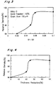
- the present invention provides a mold structure for injection molding into an interior cavity portion through a gate a light molten alloy which is in a semi-molten state where a solid phase and a liquid phase of the alloy coexist or in a full molten state remaining at a temperature just above the liquidus point of the alloy, wherein a ratio S1/S2 of a sectional area S1 of the gate with respect to a maximum sectional area S2 of the internal cavity perpendicular to the molten metal flowing direction is set to be not less than 0.06.
- the gate sectional area larger than such special value to the maximum sectional area of the internal cavity portion in the direction perpendicular to the metal flowing, or poured, direction toward the cavity, the molten alloy can become in the laminar flow state in the cavity. As a result, no generation of such gas defects as blow holes or shrinkage voids is substantially observed in the injection-molded product produced.
- the lower limit of the areal ratio S1/S2 should be 0.06. If the areal ratio S1/S2 is less than 0.06, as shown in Fig. 3, the relative density of the product is drastically lowered because the generation rate of such gas defects increases.
- the upper limit of the areal ratio S1/S2 of the mold preferably may be 0.50. If the ratio S1/S2 is more than 0.5, the relative density of the molded material would be on almost the same level as that of the conventional die cast, causing an advantage of using such semi-melt injection molding method to disappear.
- the melt filled in the corresponding thick portion of the cavity is apt to be finally solidified to produce shrinkage cavities or voids in the portion.
- the core pins cause the semi-molten alloy which is solidifying to flow plastically, resulting in crushing of the shrinkage cavities in the product.
- the semi-melt injection molding is preferably performed at the solid fraction which may be prepared to be not less than 10%.
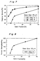
- the average solid grain size is liable to become small and the creep characteristics at high temperature are liable to be lowered as shown in Fig. 6.
- injection molding must be performed under the condition that not only the solid fraction is not less than 5%, but also the average crystal grain size in the solid phase contained in the melt is not less than 50 ⁇ m.
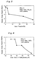
- the relative density of the injection-molded material of the present invention can be improved by optionally being pressed or forged.
- the draft (a ratio of difference of the initial thickness and the deformed thickness of the material with respect to the initial thickness) due to pressing or forging should be set to not less than 25%. The reason is that the relative density, as shown in Fig. 4, is rapidly increased from the draft of 20% and is saturated at 25%.
- the method of the present invention is preferably applied to magnesium based alloy containing 4 to 9.5% by weight of aluminum as a main alloying component, as the light alloy.
- aluminum content is smaller than 4% by weight, an enhancement in mechanical strength is not expected.
- a content exceeding 9.5% by weight can significantly lower workability (by limiting upsetting rate).
- the light alloy obtained by the present method is preferably subjected to heat treatment for Temper T6 (composed of a solution treating followed by an artificial aging or a single age hardening treatment) for further improving the mechanical strength.
- the present invention can provide the molded material of a light alloy free from gas defects by injection molding process, so that such molded material, even if it may have a rough shape, can be forged into a final product having excellent mechanical strength and precise dimensions.
- a magnesium based alloy is injection-molded by using a semi-melt injection molding machine, as shown in Figs. 1A and 1B.
- a cylinder 31 is provided with a screw 32 therein, a high-speed injection mechanism 33 at the rear end and a mold 4 at the front end.
- the mold 4 comprises two separable half-molds 4a and 4b having each plans in contact with each other, in which each concave to form at least a cavity 40 for molding is shaped.
- a plurality of heaters 35 are arranged around the cylinder 31 in fixed intervals along the cylinder axis, which thereby heat and melt the alloy material in order while the material is being charged through a hopper 36 provided at the inlet end of the cylinder 31.
- the molten material which is heated at a predetermined temperature in the cylinder 31, is pressurized by pushing the screw rotor 32 inside the cylinder 31 toward the front end and then injected into the cavity in the mold 4, to solidify the solid body to be shaped to the inversive inner profile of the cavity 40.
- the injection-molded rough-surfaced product 1 is removed after the half-molds 4a and 4b are separated as shown in Fig. 1B, and then placed and forged between upper and lower forging dies 91 and 92 as shown in Figs. 1C and 1D.
- the product 1 is separated between the forging dies 91 and 92 as shown in Fig. 1E to obtain a forged product 2 as shown in Fig. 1F.
- the forged product 2 is machined for finishing and then subjected to heat treatment to temper T6.
- the Alloys A to C were used as magnesium based alloy, and as such molding machine, Model JLM-450E manufactured by Nippon Seikosho Co. may be used under the conditions as for example shown in Table 2.
- Composition of Magnesium Alloy (wt%) Al Zn Mn Fe Cu Ni Mg Alloy A 7.2 0.7 0.17 0.002 0.001 0.008
- Bal Alloy B 6.2 0.9 0.24 0.003 0.001 0.008
- Bal Alloy C 9.2 0.7 0.22 0.004 0.002 0.008 Bal Condition of Injection Molding Injection pressure 80 Mpa Injection speed 2 m/s Mold temperature 180°C
- the mechanically cut pellets of the magnesium alloy C having the composition as shown in the Table 1, are charged into the hopper 36 of the above injector.
- the powder is heated at a temperature adjusted such that pellets begin to be gradually molten when moved at the position of about 1/4 of the whole length in the interior of the cylinder from the hopper and to reach the desired solid fraction in the state of solid liquid phases mixture at the position of about 1/2 of the whole length from the hopper.
- the melt to the solid fraction of about 10% prior to injecting it was injected into the mold so as to obtain the average solid grain size of about 50 ⁇ m in the molded alloy.
- a sample of a shape of 16 cm in diameter and 22.5 mm in length, having the relative density of 96% was made of the injection-molded material of the above alloy C and forged at the temperature of 300°C to different forging draft percentages.
- a relation between the forging draft and the relative density of the product is shown in Fig. 4.
- the relative density increases with an increase in forging draft.
- the relative density is 99% at the forging draft of 25%, and is saturated with the higher draft.
- the injection-molded materials were prepared by injection-molding the above alloy C under the conditions that the average solid grain size is fixed to 50 ⁇ m and the solid fraction is changed, using a mold of the area ratio S1/S2 of 0.1. Creep characteristics of the resulting injection molded materials was examined at 125°C under 50 MPa. The solid fraction was determined by measuring the area proportion in the microstructure of the molded product, using image analysis.
- the injection-molded materials were prepared by injection-molding the same alloy C under the conditions that the average solid fraction was fixed constant and the average crystal grain size ( ⁇ m) of the solid phase in the melt was changed, using a mold having the areal ratio S1/S2 of 0.1.
- Fig. 6 shows the obtained relation between the average solid fraction and steady creep rate, in which steady creep the rate is decreased with an increase in solid grain size.
- the excellent high-temperature creep characteristics are obtained at the solid fraction of not less than 5%.
- Example 1 In the same manner as described in Example 1 except for using alloys A and B as specified in Table 1, injection molding was performed and the relation between the solid fraction and the relative density of the alloys A and B was studied wherein the grain size of the solid phase was adjusted to 10%.
- the Alloy B is apt to show poorer run as a melt in a cavity of the mold and apt to be lower in density as a solids than the Alloy A, on the same conditions of molding with respect to both the Alloys,
- the Alloy C was injection molded using the mold having the areal ratio S1/S of 0.2, at the solid fraction of 10% in the same manner as described in Example 1.
- Example 3 the cavity of the mold was evacuated for 5 seconds before injection and the injection pressure was maintained to the melt filled in the cavity at 80 MPa until solidification of the melt has finished.
- Example 4 evacuation was not performed and the injection pressure was maintained at 80 MPa until solidification has finished.
- a filter 44f having pores whose diameter is smaller than that of the solid grain size of the solid phase in the molten light alloy, may be provided in the mold, allowing the molten metal not to be transferred to the evacuation path 44p of the mold.
- the position of the gate in the mold such that the distance between the side wall of the cavity initially is in contact with the molten metal and the gate is elongated as far as possible, and to contrive the mold design of reducing the speed of the molten metal when the mold side wall is contacted therewith.
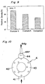
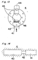
- a ring-shaped product to be molded preferably at least two gates 42 and 42 are provided separately around the rim of the ring, as shown in Fig. 12, thereby to adjust the injecting speed of the molten metal from the gates to not less than 30 m/second and to supply the molten metal flow along the tangent line to the center of the ring.
- a porous material 46 is arranged on the side wall of the cavity to be in earliest contact with the injected molten metal, thereby making it possible to reduce the metal flow speed when the mold side wall is contacted with the molten metal. Also, it is preferable to enhance the solid fraction in the melt at the portion which the molten metal reaches the latest.
- the temperature of the melt may be controlled in the respective heating zones by heaters 35 around the injection cylinder 31, thereby to change the solid fraction in the molten alloy longitudinally along the cylinder 31, as shown in fig. 1A.
- the cavity of the mold may have a form of rectangular hexahedron.
- the gate 42 connected with the runner 41 is preferably provided at the end portion of the cavity 40 elongated in the longitudinal direction, as shown in Fig. 14, to elongate the distance between the side wall of the cavity 40 to be in contact with the earliest molten metal as long as possible.
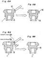
- a pealed or broken defect is apt to occur at the root portion of the gate 12 of the product 1 at the time of separation of the runner 11 by cutting it at the gate, as shown in Figs. 15A and 15B.
- a two-stage gate structure as shown in Fig. 16A, wherein the area of the gate 12a (for example, section of the gate; 4 mm in width, 2.0 mm in thickness) on the cavity side (product side) is larger than that of the gate 12b (for example, section of the gate; 4 mm in width, 1.7 mm in thickness) which is on the runner side and away by o.1 mm from the cavity.
- the gate 12a for example, section of the gate; 4 mm in width, 2.0 mm in thickness
- the gate 12b for example, section of the gate; 4 mm in width, 1.7 mm in thickness
- the product is separated at the smaller (thinner) gate 12b from the runner 11 by bending the runner, and the remaining portion of the runner, or the gate 12a, on the product surface is then ground to be removed; consequently, the smooth surface at the portion of the product can be easily obtained, without forming such a pealed defect due to the gate, as shown in Fig. 16B.
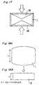
- a pair of non-deformed regions 18 and 18 are formed in the material 1 under the center upper and lower surfaces which are pressed opposite to each other, as shown in Fig. 17, and shrinkage cavities in the region thereof is possible to be left without being crushed.
- an injection-molded product 1 may be molded in advance into a barrel-shaped cross section, in which the central upper and lower surfaces to be pressed are expanded as shown in Fig. 18A, and then such injection-molded product 1 may be forged so as to deform the portions under the convexed barrel surfaces with higher draft.
- a forged product 2 having a rectangular cross section is formed by forging, as shown in Fig. 18B.
Landscapes
- Engineering & Computer Science (AREA)
- Mechanical Engineering (AREA)
- Moulds For Moulding Plastics Or The Like (AREA)
- Forging (AREA)
- Injection Moulding Of Plastics Or The Like (AREA)
Applications Claiming Priority (3)
| Application Number | Priority Date | Filing Date | Title |
|---|---|---|---|
| JP263893/97 | 1997-09-29 | ||
| JP26389397 | 1997-09-29 | ||
| JP26389397A JP3416036B2 (ja) | 1997-09-29 | 1997-09-29 | マグネシウム合金射出成形用金型構造及び該金型構造を用いたマグネシウム合金部品の成形方法 |
Publications (2)
| Publication Number | Publication Date |
|---|---|
| EP0904875A1 true EP0904875A1 (fr) | 1999-03-31 |
| EP0904875B1 EP0904875B1 (fr) | 2002-11-06 |
Family
ID=17395727
Family Applications (1)
| Application Number | Title | Priority Date | Filing Date |
|---|---|---|---|
| EP98118392A Expired - Lifetime EP0904875B1 (fr) | 1997-09-29 | 1998-09-29 | Procédé de moulage par injection d'un aliage en métal léger |
Country Status (5)
| Country | Link |
|---|---|
| US (1) | US6334478B2 (fr) |
| EP (1) | EP0904875B1 (fr) |
| JP (1) | JP3416036B2 (fr) |
| DE (1) | DE69809166T2 (fr) |
| ES (1) | ES2186959T3 (fr) |
Cited By (3)
| Publication number | Priority date | Publication date | Assignee | Title |
|---|---|---|---|---|
| DE10033165C1 (de) * | 2000-07-07 | 2002-02-07 | Hengst Walter Gmbh & Co Kg | Vorrichtung und Verfahren zum Schmelzen und Fördern von Material |
| EP2400353A1 (fr) * | 2010-06-22 | 2011-12-28 | The Swatch Group Research and Development Ltd. | Aiguille de pièce d'horlogerie |
| CN107790668A (zh) * | 2017-09-01 | 2018-03-13 | 东风精密铸造安徽有限公司 | 一种半固态金属触变注射成型设备 |
Families Citing this family (9)
| Publication number | Priority date | Publication date | Assignee | Title |
|---|---|---|---|---|
| GB2354471A (en) * | 1999-09-24 | 2001-03-28 | Univ Brunel | Producung semisolid metal slurries and shaped components therefrom |
| JP3837104B2 (ja) * | 2002-08-22 | 2006-10-25 | 日精樹脂工業株式会社 | カーボンナノ材と金属材料の複合成形方法及び複合金属製品 |
| DE10319630A1 (de) * | 2003-05-02 | 2004-11-18 | Bayerische Motoren Werke Ag | Verfahren zur Herstellung eines Bauteils aus einem Magnesiumkern mit einer Aluminiumummantelung |
| US20060054295A1 (en) * | 2004-07-12 | 2006-03-16 | Grassi John R | Method of forming a part with a globular microstructure |
| KR20050093719A (ko) * | 2005-04-27 | 2005-09-23 | 갑산메탈 주식회사 | 반고체 단조법 |
| DE102012100458A1 (de) * | 2012-01-20 | 2013-07-25 | Martinrea Honsel Germany Gmbh | Verfahren zur Herstellung eines mit mindestens einem Hohlraum versehenen Leichtmetall-Bauteils |
| DE102013103672A1 (de) | 2013-04-11 | 2014-10-30 | Fraunhofer-Gesellschaft zur Förderung der angewandten Forschung e.V. | Poren-Druckguss |
| CN104959578B (zh) * | 2015-06-30 | 2017-01-11 | 昆明理工大学 | 一种复合式制备半固态浆料的装置 |
| JP7202477B2 (ja) * | 2019-09-30 | 2023-01-11 | 本田技研工業株式会社 | 内燃機関用ピストンの製造方法および製造装置 |
Citations (4)
| Publication number | Priority date | Publication date | Assignee | Title |
|---|---|---|---|---|
| US5040589A (en) * | 1989-02-10 | 1991-08-20 | The Dow Chemical Company | Method and apparatus for the injection molding of metal alloys |
| EP0572683A1 (fr) * | 1992-01-13 | 1993-12-08 | Honda Giken Kogyo Kabushiki Kaisha | Procede de moulage de pieces en alliage d'aluminium et pieces ainsi produites |
| EP0665299A1 (fr) * | 1993-12-17 | 1995-08-02 | Mazda Motor Corporation | Matériau de moulage en alliage de magnésium pour traitement plastique, pièces fabriquées avec cet alliage et procédé de fabrication |
| EP0718059A1 (fr) * | 1994-12-22 | 1996-06-26 | Alusuisse-Lonza Services AG | Décrotteur d'oxyde |
Family Cites Families (1)
| Publication number | Priority date | Publication date | Assignee | Title |
|---|---|---|---|---|
| DE3942686C2 (de) * | 1988-12-23 | 1998-07-09 | Ngk Insulators Ltd | Verfahren zum Spritzgießen von Keramik |
-
1997
- 1997-09-29 JP JP26389397A patent/JP3416036B2/ja not_active Expired - Fee Related
-
1998
- 1998-09-29 US US09/161,833 patent/US6334478B2/en not_active Expired - Fee Related
- 1998-09-29 ES ES98118392T patent/ES2186959T3/es not_active Expired - Lifetime
- 1998-09-29 DE DE69809166T patent/DE69809166T2/de not_active Expired - Fee Related
- 1998-09-29 EP EP98118392A patent/EP0904875B1/fr not_active Expired - Lifetime
Patent Citations (4)
| Publication number | Priority date | Publication date | Assignee | Title |
|---|---|---|---|---|
| US5040589A (en) * | 1989-02-10 | 1991-08-20 | The Dow Chemical Company | Method and apparatus for the injection molding of metal alloys |
| EP0572683A1 (fr) * | 1992-01-13 | 1993-12-08 | Honda Giken Kogyo Kabushiki Kaisha | Procede de moulage de pieces en alliage d'aluminium et pieces ainsi produites |
| EP0665299A1 (fr) * | 1993-12-17 | 1995-08-02 | Mazda Motor Corporation | Matériau de moulage en alliage de magnésium pour traitement plastique, pièces fabriquées avec cet alliage et procédé de fabrication |
| EP0718059A1 (fr) * | 1994-12-22 | 1996-06-26 | Alusuisse-Lonza Services AG | Décrotteur d'oxyde |
Cited By (7)
| Publication number | Priority date | Publication date | Assignee | Title |
|---|---|---|---|---|
| DE10033165C1 (de) * | 2000-07-07 | 2002-02-07 | Hengst Walter Gmbh & Co Kg | Vorrichtung und Verfahren zum Schmelzen und Fördern von Material |
| US7066726B2 (en) | 2000-07-07 | 2006-06-27 | Hengst Gmbh & Co. Kg | Device and method for melting and conveying material |
| EP2400353A1 (fr) * | 2010-06-22 | 2011-12-28 | The Swatch Group Research and Development Ltd. | Aiguille de pièce d'horlogerie |
| WO2011161077A1 (fr) * | 2010-06-22 | 2011-12-29 | The Swatch Group Research And Development Ltd | Aiguille de piece d'horlogerie |
| CN103097967A (zh) * | 2010-06-22 | 2013-05-08 | 斯沃奇集团研究和开发有限公司 | 钟表指针 |
| US9329572B2 (en) | 2010-06-22 | 2016-05-03 | The Swatch Group Research And Development Ltd. | Timepiece hand |
| CN107790668A (zh) * | 2017-09-01 | 2018-03-13 | 东风精密铸造安徽有限公司 | 一种半固态金属触变注射成型设备 |
Also Published As
| Publication number | Publication date |
|---|---|
| JP3416036B2 (ja) | 2003-06-16 |
| EP0904875B1 (fr) | 2002-11-06 |
| US6334478B2 (en) | 2002-01-01 |
| DE69809166T2 (de) | 2003-06-12 |
| ES2186959T3 (es) | 2003-05-16 |
| JPH11104799A (ja) | 1999-04-20 |
| US20010013402A1 (en) | 2001-08-16 |
| DE69809166D1 (de) | 2002-12-12 |
Similar Documents
| Publication | Publication Date | Title |
|---|---|---|
| KR100646718B1 (ko) | 다이 주조 니켈-기제 초합금 제품 | |
| DE69823966T2 (de) | Verfahren und vorrichtung zur herstellung von metallischen gläsern | |
| EP0867246B1 (fr) | Procédé et dispositif de moulage par injection de métaux à l'état semi-liquide | |
| EP0904875B1 (fr) | Procédé de moulage par injection d'un aliage en métal léger | |
| US6079477A (en) | Semi-solid metal forming process | |
| EP0905266B1 (fr) | Procédé de fabrication de produits en alliage léger avec moulage par injection à l'état semi-solide | |
| EP0968781B1 (fr) | Procédé et dispositif de moulage par injection de métaux à l'état semi-liquide | |
| US6502624B1 (en) | Multiproperty metal forming process | |
| US4709461A (en) | Method of forming dense ingots having a fine equiaxed grain structure | |
| Gjestland et al. | Advancements in high pressure die casting of magnesium | |
| CA2227828C (fr) | Procede de formation d'un metal semi-solide | |
| US6818080B2 (en) | Method for manufacturing shaped light metal article | |
| EP1153151B1 (fr) | Pieces moulees sous pression en superalliage | |
| KR100338925B1 (ko) | 세미 솔리드 금형 | |
| KR100856097B1 (ko) | 용탕단조 및 열간성형에 의한 제조방법 | |
| DE3817688A1 (de) | Kokillengussverfahren, insbesondere fuer metalle, sowie vorrichtung und giessform zur verwendung bei diesem verfahren | |
| JPH09241784A (ja) | ダイカスト品 | |
| JPH0288735A (ja) | 延性と耐摩耗性を兼ね備えた複合材料、その製造方法およびその用途 | |
| US20030145918A1 (en) | Method for manufacturing plastic worked article | |
| JPH05245610A (ja) | 高強度構造部材の製造方法 | |
| JPH05245609A (ja) | 急冷凝固合金粉末を用いた高強度構造部材の製造方法 |
Legal Events
| Date | Code | Title | Description |
|---|---|---|---|
| PUAI | Public reference made under article 153(3) epc to a published international application that has entered the european phase |
Free format text: ORIGINAL CODE: 0009012 |
|
| AK | Designated contracting states |
Kind code of ref document: A1 Designated state(s): DE ES FR GB IT |
|
| AX | Request for extension of the european patent |
Free format text: AL;LT;LV;MK;RO;SI |
|
| 17P | Request for examination filed |
Effective date: 19990916 |
|
| AKX | Designation fees paid |
Free format text: DE ES FR GB IT |
|
| 17Q | First examination report despatched |
Effective date: 20010220 |
|
| GRAG | Despatch of communication of intention to grant |
Free format text: ORIGINAL CODE: EPIDOS AGRA |
|
| RTI1 | Title (correction) |
Free format text: METHOD OF INJECTION MOLDING A LIGHT ALLOY |
|
| GRAG | Despatch of communication of intention to grant |
Free format text: ORIGINAL CODE: EPIDOS AGRA |
|
| GRAH | Despatch of communication of intention to grant a patent |
Free format text: ORIGINAL CODE: EPIDOS IGRA |
|
| GRAH | Despatch of communication of intention to grant a patent |
Free format text: ORIGINAL CODE: EPIDOS IGRA |
|
| GRAA | (expected) grant |
Free format text: ORIGINAL CODE: 0009210 |
|
| AK | Designated contracting states |
Kind code of ref document: B1 Designated state(s): DE ES FR GB IT |
|
| REG | Reference to a national code |
Ref country code: GB Ref legal event code: FG4D |
|
| REF | Corresponds to: |
Ref document number: 69809166 Country of ref document: DE Date of ref document: 20021212 |
|
| REG | Reference to a national code |
Ref country code: ES Ref legal event code: FG2A Ref document number: 2186959 Country of ref document: ES Kind code of ref document: T3 |
|
| ET | Fr: translation filed | ||
| PGFP | Annual fee paid to national office [announced via postgrant information from national office to epo] |
Ref country code: FR Payment date: 20030909 Year of fee payment: 6 |
|
| PLBE | No opposition filed within time limit |
Free format text: ORIGINAL CODE: 0009261 |
|
| STAA | Information on the status of an ep patent application or granted ep patent |
Free format text: STATUS: NO OPPOSITION FILED WITHIN TIME LIMIT |
|
| PGFP | Annual fee paid to national office [announced via postgrant information from national office to epo] |
Ref country code: GB Payment date: 20030924 Year of fee payment: 6 |
|
| PGFP | Annual fee paid to national office [announced via postgrant information from national office to epo] |
Ref country code: ES Payment date: 20031021 Year of fee payment: 6 |
|
| 26N | No opposition filed |
Effective date: 20030807 |
|
| PG25 | Lapsed in a contracting state [announced via postgrant information from national office to epo] |
Ref country code: GB Free format text: LAPSE BECAUSE OF NON-PAYMENT OF DUE FEES Effective date: 20040929 |
|
| PG25 | Lapsed in a contracting state [announced via postgrant information from national office to epo] |
Ref country code: ES Free format text: LAPSE BECAUSE OF NON-PAYMENT OF DUE FEES Effective date: 20040930 |
|
| GBPC | Gb: european patent ceased through non-payment of renewal fee |
Effective date: 20040929 |
|
| PG25 | Lapsed in a contracting state [announced via postgrant information from national office to epo] |
Ref country code: FR Free format text: LAPSE BECAUSE OF NON-PAYMENT OF DUE FEES Effective date: 20050531 |
|
| REG | Reference to a national code |
Ref country code: FR Ref legal event code: ST |
|
| PG25 | Lapsed in a contracting state [announced via postgrant information from national office to epo] |
Ref country code: IT Free format text: LAPSE BECAUSE OF NON-PAYMENT OF DUE FEES;WARNING: LAPSES OF ITALIAN PATENTS WITH EFFECTIVE DATE BEFORE 2007 MAY HAVE OCCURRED AT ANY TIME BEFORE 2007. THE CORRECT EFFECTIVE DATE MAY BE DIFFERENT FROM THE ONE RECORDED. Effective date: 20050929 |
|
| REG | Reference to a national code |
Ref country code: ES Ref legal event code: FD2A Effective date: 20040930 |
|
| PGFP | Annual fee paid to national office [announced via postgrant information from national office to epo] |
Ref country code: DE Payment date: 20081002 Year of fee payment: 11 |
|
| PG25 | Lapsed in a contracting state [announced via postgrant information from national office to epo] |
Ref country code: DE Free format text: LAPSE BECAUSE OF NON-PAYMENT OF DUE FEES Effective date: 20100401 |