EP0904794B1 - Soufflet avec un système de remplissage automatique - Google Patents
Soufflet avec un système de remplissage automatique Download PDFInfo
- Publication number
- EP0904794B1 EP0904794B1 EP98850147A EP98850147A EP0904794B1 EP 0904794 B1 EP0904794 B1 EP 0904794B1 EP 98850147 A EP98850147 A EP 98850147A EP 98850147 A EP98850147 A EP 98850147A EP 0904794 B1 EP0904794 B1 EP 0904794B1
- Authority
- EP
- European Patent Office
- Prior art keywords
- gas
- patient
- bellows
- breathing circuit
- flow
- Prior art date
- Legal status (The legal status is an assumption and is not a legal conclusion. Google has not performed a legal analysis and makes no representation as to the accuracy of the status listed.)
- Expired - Lifetime
Links
Images
Classifications
-
- A—HUMAN NECESSITIES
- A61—MEDICAL OR VETERINARY SCIENCE; HYGIENE
- A61M—DEVICES FOR INTRODUCING MEDIA INTO, OR ONTO, THE BODY; DEVICES FOR TRANSDUCING BODY MEDIA OR FOR TAKING MEDIA FROM THE BODY; DEVICES FOR PRODUCING OR ENDING SLEEP OR STUPOR
- A61M16/00—Devices for influencing the respiratory system of patients by gas treatment, e.g. ventilators; Tracheal tubes
- A61M16/10—Preparation of respiratory gases or vapours
-
- A—HUMAN NECESSITIES
- A61—MEDICAL OR VETERINARY SCIENCE; HYGIENE
- A61M—DEVICES FOR INTRODUCING MEDIA INTO, OR ONTO, THE BODY; DEVICES FOR TRANSDUCING BODY MEDIA OR FOR TAKING MEDIA FROM THE BODY; DEVICES FOR PRODUCING OR ENDING SLEEP OR STUPOR
- A61M16/00—Devices for influencing the respiratory system of patients by gas treatment, e.g. ventilators; Tracheal tubes
- A61M16/22—Carbon dioxide-absorbing devices ; Other means for removing carbon dioxide
Definitions
- the present invention relates to anesthesia systems used to provide an anesthetic agent to a patient undergoing an operation.
- anesthesia systems are utilized in operating rooms and comprise various equipment necessary to anesthetize the patient and maintain the patient in that state until the operation is completed and it is possible to terminate the introduction of the anesthetic agent.
- Such systems comprise various pressure regulators, flow control devices, gas mixing devices and vaporizers to vaporize a volatile liquid anesthetic and to introduce the anesthetic laden gases into the patient.
- the patient is connected to the system by means of a face mask or other device and which interfaces with the anesthesia system via a patient circuit that may typically have an inspiratory limb through which the gases are introduced into the patient and an expiratory limb that conveys the exhaled gases from the patient.
- the overall flow of gases to and from the patient may be in a generally closed circuit, commonly referred to as the circle system, that is, the patient is connected to a substantially closed volume supply of gases and rebreathes certain of those exhaled gases supplemented by fresh gas.
- a ventilator As the driving force to the circle breathing circuit, and, of course, to the patient, a ventilator is used and which basically breathes for the patient since the patient is under anesthesia and is unable to carry out the normal spontaneous breathing functions.
- the ventilator therefore, provides a quantity of the gas containing a predetermined metered quantity of the anesthetic agent along with other gases such as nitrous oxide and, of course, a life sustaining percentage of oxygen.
- That gas containing the anesthetic may typically be delivered through an intermediate mechanism such as a bellows.
- the driving gas from the ventilator does not contain the anesthetic agent but is used to simply power the bellows to collapse that bellows to deliver the aforementioned anesthetic containing gas from the bellows to the patient.
- other driving means such as an electromechanical or mechanical means are also used.
- the anesthetic laden gas is delivered to the inspiratory limb of the circle patient breathing circuit and is introduced into the patient to provide anesthesia to that patient.
- That anesthetic gas to the inspiratory limb is provided by a source of gases, including fresh gas, oxygen and generally nitrous oxide, that is mixed to a predetermined mixture in a gas mixer and the mixed gases are then passed through an agent vaporizer where the anesthetic agent is introduced into those gases.
- the exhalation gases pass through the expiratory limb where they are recirculated back to the inspiratory limb where they are again inhaled by the patient. In this manner, the system is closed and which allows the optimum use of the rather expensive anesthetic agent. If the fresh gas added to the circuit exceeds the net of gases taken up by the patient or leaked from the circuit, the excess gases are popped off via a pop-off valve.
- One difficulty with such system is that on occasion, there is a loss of gas within the system, that is , there may be a patient disconnect where one of the limbs to the patient becomes disconnected, or, alternatively, there may simply be a leak in the system such that the gas that normally is supplied to the patient is released to the atmosphere and the patient is not receiving the amount of gas intended by the clinician.
- the clinician may continually watch the bellows movement to see if there is a lessening of the expansion and note that indication as evidence of a leak in the patient circuit.
- the anesthesia system of the present invention includes a means of detecting when there is a disconnect or large leak in the system, reduce the flow to the patient and then carry out automatic refilling of the system at a high flow when the leak has been corrected and then return the anesthesia system to the original conditions.
- the gas delivery system maintains the set inspired gas composition delivered to the patient.
- Set inspired composition may be explicitly defined by the user or implicitly defined via expired gas composition setting as set expired agent concentration control.
- the present invention relates to an anesthesia system that determines when a transitory disconnect or large leak has taken place in the breathing circuit. Upon recognition of the existence of such disconnect or large leak, the system reduces the fresh gas flow to a lower predetermined flow and retains the flow at the lower setting while the disconnect or leak is being corrected. Upon correction of the disconnect or leak, the system automatically recognizes that the fault has been corrected and increases the fresh gas flow to quickly refill the breathing circuit with the particular composition of breathing gas mixture established by the clinician.
- the system thus further includes a means to determine when the breathing circuit has again been filled and automatically returns the fresh gas flow back to the original setting.
- the system not only recognizes the existence of disconnections or large leaks but it carries out the refilling of the breathing circuit with a high flow of the correct gas composition and, when that breathing circuit has been refilled, the system automatically restores the previously established flows with the desired composition of breathing gas originally established.
- the clinician need not visually establish the existence of the leaks or disconnects such that the sole reliance of the clinician is eliminated and that clinician can be paying attention to other functions. Therefore, since the recognition of the leak or disconnect is automatic, the system can immediately reduce the gas flow. This minimizes gas pollution into the operating room and reduces wastage of anesthetic agent.
- the present system carries out the high flow re-establishment of the volume in the breathing circuit with gas at the proper concentrations and when the circuit has been refilled, return the flow and concentration to the original value, thus the clinician need not take any further measures to bring the system fresh gas flows and concentrations to the desired values other than to correct a disconnect or to alleviate the large leak.
- the time that the patient circuit takes to refill is also minimized since the system senses the correction of the circuit fault and takes the corrective action to restore the gas to the breathing circuit without user intervention, that is, the refilling operation is automatic and does not require any user action to refill the circuit.
- the refilling operation is automatic and does not require any user action to refill the circuit.
- Increasing the gas flow also speeds up the recovery time of the gas volume.
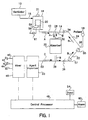
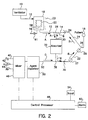
- FIGS. 1 and 2 are block diagrams of the components of an anesthesia system used to carry out the present invention.
- a ventilator 10 is provided and which may be of the type shown and described in U.S. Patent 5,315,989 assigned to the present applicant and the disclosure of which is incorporated herein by reference.
- the present system can also be applied to the anesthesia ventilator system disclosed in U.S. Patent 5,094,235 of Westenskow.
- the ventilator of the aforementioned U.S. Patent 5,315,989 has an inhalation cycle and an exhalation cycle controlled by a central processing unit.
- the ventilator 10 provides gas to the patient during the inhalation cycle via a conduit 12 to the patient breathing circuit 14 where it is delivered to the patient 16.
- the ventilator 10 typically includes a bellows container 18 and air or other powering gas is supplied to the bellows container 18 via conduit 15, exterior of the bellows 20 and which then collapses the bellows 20 to force gas within the bellows 20 to the patient 16.
- a means of determining the amount of inflation of the bellows 20 is also included and which indicates the maximum volume of gas that is contained in the bellows 20 at the end of its expansion. That means may be a top bellow sensor 21 located at the top of the bellows container 18 and which senses when the top of the bellows 20 approaches the top of the bellows container 18.
- a bellows position sensor 23 can be used as will be explained and which may be positioned along the side of the bellows container 18 and which can detect the position of the top of the bellows 20 in any one of many positions within the bellows container 18.
- An example of such a bellows position sensor 23 is shown and described in the aforementioned Westenskow U.S. Patent 5,094,235.
- the patient breathing circuit 14 itself conventionally includes an inspiratory limb 22 and an expiratory limb 24 and the patient 16 is connected to a wye connection 26 located intermediate the inspiratory and the expiratory limbs 22,24.
- the means of connection to the patient 16 may be an endotracheal tube, face mask or other interface between the patient 16 and the patient breathing circuit 14.
- gas is delivered to the patient 16 by means of a powering gas from ventilator 10 that collapses the bellows 20 to drive the gas into conduit 12 and then into the tee 28 where the gas enters a conduit 30 and passes through an absorber 32. After passing through the absorber 32, the gas enters the inspiratory limb 22 of the patient breathing circuit 14 to be administered to the patient 16. As the patient exhales, that exhalation, now laden with CO 2 , passes through the expiratory limb 24 where it again passes through the tee 28 and continues to the absorber 32 where the CO 2 is eliminated by a CO 2 absorbing material, such as sodalime.
- a CO 2 absorbing material such as sodalime.
- a pair of check valves 34 and 36 are positioned in the patient breathing circuit 14 in the expiratory and inspiratory limbs 24 and 22, respectively, to maintain the flow of gas in the proper direction around the circle patient breathing circuit 14.
- a flow of fresh gas is also introduced into the patient breathing circuit 14 and, as shown, is added at a tee 38 and thus into the inspiratory limb 22 of the patient breathing circuit 14.
- That flow of fresh gas is provided from a source of gas, typically oxygen and nitrous oxide to aid in anesthetizing the patient.
- a source of gas typically oxygen and nitrous oxide to aid in anesthetizing the patient.
- oxygen 40, nitrous oxide 42 and air 44 may be through a central piping system of a hospital or may be through the use of individual cylinders of such gases.
- the gases are mixed in a gas mixer 46 in the proportion desired by the user.
- the actual control of the proportions and the flow through the gas mixer 46 is, in the preferred embodiment, controlled by a central processing unit (CPU) 48 as will be described.
- the mixed gas from the gas mixer 46 then passes through an agent vaporizer 50 where liquid anesthetic agent is vaporized and added to the stream of gas such that anesthetic laden gas continues into a conduit 52 and enters the patient breathing circuit 14 at the tee 38.
- control of the agent vaporizer 50 is by means of the CPU 48 and which determines the percentage concentration of anesthetic agent that is in the gas that enters the patient breathing circuit 14 and thus that is supplied to the patient 16 to induce and maintain anesthesia.
- the CPU 48 is, in turn, controlled by an input device 54 provided so that the clinician can input the data needed to determine the various parameters to provide the fresh gas flow and anesthetic concentration desired to anesthetize the patient.
- the input to the CPU 48 may be the flow of fresh gas to the patient as well as the concentrations of the various gases mixed in the gas mixer 46 and the concentration of anesthetic to be added to the mixed fresh gas by the agent vaporizer 50.
- the overall flow scheme of the present conventional system is therefore such that the gas in the bellows 20 is forced by the ventilator 10 into conduit 12 in accordance with the arrows A during the inhalation cycle of the patient 16.
- the gas thus passes through the tee 28 and through absorber 32 where it further passes through tee 38 and into the inspiratory limb 22 of the patient breathing circuit 14.
- tee 38 fresh gas containing a predetermined concentration of an anesthetic agent is joined with the gas from the bellows 20 and proceeds with the gases already circulating in patient breathing circuit 14 and administered to the patient 16.
- the exhaled gas passes through the expiratory limb 24 of the patient breathing circuit 14 through tee 28 and continues through the conduit 12 and into the bellows 20.
- fresh gas that continuously flows into the circuit 14 from conduit 52 is also directed towards the bellows 20 after passing through the patient breathing circuit 14.
- any excess gas is popped off from the bellows 20 via pop-off valve 58 and exits the system via conduit 59 and typically into a gas scavenging system, not shown.
- a flow sensor 61 is located in the flow of gas from the pop-off valve 58 and senses the flow from that pop-off valve. As such, the flow exits the pop-off valve 58 due to the pressure differential between the interior of the bellows 20 and the ambient pressure and is an indication of the position of the bellows 20 and, as explained, an indication of the maximum amount of gas that is introduced into the bellows 20. That is, the gas escapes the pop-off valve 58 due to the existence of excess gas in the bellows 20 when the bellows 20 reaches its uppermost position and the continued flow of gas into the bellows 20 results in an increase in pressure, opening the pop-off valve 58 releasing the gas to atmosphere or to a scavenging system.
- the existence of a flow of gas out of the pop-off valve 58 is an indication the bellows 20 has reached its uppermost position within the bellows container 18.
- a flow out of the pop-off valve 58 confirms that the bellows has reached its uppermost position.
- An alternate sensor could be employed to confirm that the bellows 20 has reached that top position including a sensor that merely detects that the pop-off valve 58 has opened to allow that excess gas to escape.
- the bellows 20 is driven downwardly by the ventilator 10.
- the unidirectional check valves 34 and 36 direct the gas from the bellows 20 to conduit 12 and through the absorber 32 where the gas is scrubbed of CO 2 . Also directed is the fresh gas from conduit 52 towards the patient 16 via inspiratory limb 22 of breathing circuit 14.
- the anesthesia system is basically a circle system where the gas continues to pass in a circle as shown by the arrows B with the addition of fresh gas and the anesthetic agent added to that gas in the direction of Arrow C as the gas passes around the circle.
- a pressure sensor 55 is present in the inspiratory limb 22 and is indicative of the pressure in the patient breathing circuit or airway, that is P AW ,and a flow sensor 57 is also present in the same inspiratory limb 22 and which detects the flow Q AW of gas in the patient circuit or airway.
- the signals representative of the pressure monitored by the pressure sensor 55 and the flow monitored by flow sensor 57 are provided to CPU 48 for purposes that will be hereinafter explained.
- the system determines when there is a leak in the breathing circuit or a loss of integrity in the system.
- various embodiments that can detect the existence of a leak, one of which is to utilize the top bellows sensor 21 that will determine whenever the bellows 20 does not reach the top of the bellows container 18, thus indicating that there is a loss of gas somewhere in the closed anesthesia system.
- the bellows position sensor 23 may be used to continuously monitor the uppermost position reached by the bellows 20 during normal respiration of the patient 16 and that bellows position sensor 23 can be activated if the bellows 20 does not return to the same maximum vertical height within the bellows container 18.
- the flow sensor 61 on the pop-off valve 58 can be used. Whenever there is no flow from the pop-off valve 58, it is an indication that the bellows 20 has not reached its uppermost position within the bellows container 18 and thus is an indication that gas is leaking from the overall breathing circuit. As a further alternative, a sensor 61 may be used at or downstream of the pop-off valve 58 that merely indicates that the pop-off valve 58 had not opened at the end of the expiration cycle of the ventilator, again, indicating that the bellows 20 did not reach its uppermost position within the bellows container 18.
- the indication of a disconnect or large leak be confirmed, for example, by determining that the bellows did not reach the top some time. Confirmation may also be drawn from the ventilator itself where it is unable to deliver the set tidal breath or minute ventilation.
- the detection of a loss of integrity in the patient circuit 14 is communicated to the CPU 48, by one of the various sensors previously described and the CPU 48 thus immediately reduces the fresh gas flow from the mixer 46 to a lower level. If not already at the low level of flow, the CPU 48 instructs the mixer to reduce the flow to a minimum set for rate i.e. 1 liter per minute, or, alternatively, in to a minimum fresh gas flow preset by the clinician. It is important to note, however, that the overall concentrations of the various gases within the flow of fresh gas are not altered, the CPU 48 merely affects the flow of the fresh gas and its composition remains the same as already established by the clinician. By immediately lowering the flow of the fresh gas to the patient circuit, the system minimizes the amount of the gas that is leaked to the atmosphere surrounding the operating room environment so that the potentially hazardous gases are minimized from being inhaled by the clinicians that are carrying out the particular operation.
- the system recognizes that the leak has been corrected.
- the leak is corrected, the fresh gas will begin to refill the patient circuit with the breathing gas. That refilling process can be recognized by the present system and appropriate further steps taken.
- the refilling can be detected by the use of the bellows position sensor 21 which will detect that the bellows 20 will begin to refill.
- the system may note a few successive breaths where the bellows 20 increases its vertical movement with each breath to assure the system that the leak has, indeed, been corrected and the integrity of the system restored.
- the correction of the leak may be determined by the pressure sensor 55 that will note a steady breath-to breath increase in pressure in the system as bellows 20 becomes refilled.
- the tidal volume will continuously increase and that volume may be detected by the flow sensor 57 and the volume obtained by integrating the detected flow along with the time of the inspiratory cycle.
- the system will recognize that the leak has been corrected and the volume in the patient circuit is gradually being refilled.
- the CPU 48 immediately increases the fresh gas flow to a large value, i.e. 15 liters per minute to quickly refill the patient breathing circuit.
- a large value i.e. 15 liters per minute to quickly refill the patient breathing circuit.
- the system of the present invention detects the refilling and determines when the system has been sufficiently refilled with fresh gas. That detection may be carried out by again detecting the flow of excess gas out of the pop-off valve 58 indicating that the bellows 20 is again reaching its uppermost point within the bellows container 18 or, again, by simply detecting that the pop-off valve 58 has indeed opened. Alternatively, the detection of the circuit refill may be by means such as the bellows position detector 23 that will note the bellows 20 is again reaching its maximum vertical extension, or by the top bellows sensor 21 that again detects that the bellows is returning to its maximum vertical position.
- the CPU 48 also notes the amount of fresh gas that is provided to the system after the system has sensed that the leak has been corrected such as the detection of the delivery of 2.5 liters of fresh gas into the patient breathing circuit. If no sensor, of any of the above, has confirmed that the system has been refilled after delivery of that volume at the high flow, the system returns the flow back to the minimum flow previously established upon the determination of a lack of integrity of the patient breathing circuit and assumes that the leak or disconnect has not really been corrected. The low flow is continued until there is again some indication through the sensors that the leak has been alleviated.
- the CPU 48 lowers the flow back to the originally set flow established by the clinician and the ventilation of the patient is returned to the conditions that existed prior to the occurrence of a leak. That reduced flow may be at lowest flow that satisfies the metabolic O 2 and agent usage demand in accordance with the system disclose in copending U.S. Patent Application Serial No. 730,508, filed November 11,1996 and entitled Method and Apparatus For Controlling an Anesthesia Delivery System and owned by the present assignee.
- the system detects the occurrence of a large leak or disconnect in a patient breathing circuit used with a patient undergoing anesthesia. At the detection of that large leak or disconnect, the system reduces the fresh gas flow, or alternatively , assures that fresh gas flow is at a low flow that is predetermined or is reduced to a set minimum.
- the system continues to monitor the patient breathing circuit and detects when the leak or disconnect has been corrected by the clinician and immediately increases the fresh gas flow to the patient breathing circuit at the same gas concentrations as were being provided to the patient to quickly refill the patient circuit.
- the system further detects when the circuit has been refilled and when that occurrence has been detected, the system returns the fresh gas flow to a lower level, such as a minimum gas flow or to the desired gas flow setting originally being provided to the patient.
Landscapes
- Health & Medical Sciences (AREA)
- Emergency Medicine (AREA)
- Pulmonology (AREA)
- Engineering & Computer Science (AREA)
- Anesthesiology (AREA)
- Biomedical Technology (AREA)
- Heart & Thoracic Surgery (AREA)
- Hematology (AREA)
- Life Sciences & Earth Sciences (AREA)
- Animal Behavior & Ethology (AREA)
- General Health & Medical Sciences (AREA)
- Public Health (AREA)
- Veterinary Medicine (AREA)
- Measurement Of The Respiration, Hearing Ability, Form, And Blood Characteristics Of Living Organisms (AREA)
- Respiratory Apparatuses And Protective Means (AREA)
- Percussion Or Vibration Massage (AREA)
- Confectionery (AREA)
- Formation And Processing Of Food Products (AREA)
- Containers And Packaging Bodies Having A Special Means To Remove Contents (AREA)
Claims (10)
- Système d'anesthésie comprenant un ventilateur (10) ayant un cycle inspiratoire pour fournir du gaz de respiration à un patient par l'intermédiaire d'un circuit de respiration du patient (14) et un cycle expiratoire dans lequel le patient exhale, et un mélangeur de gaz (40, 42, 44, 46, 50) adapté pour fournir du gaz frais de composition donnée au circuit de respiration du patient à un premier débit, caractérisé en ce que ledit système comprend des moyens (21, 23, 61) pour détecter une fuite dans un circuit de respiration du patient, des moyens (48) pour réduire le débit de gaz depuis le mélangeur de gaz vers le circuit de respiration du patient à un deuxième débit inférieur après détection d'une fuite, des moyens pour détecter lorsqu'une fuite a été corrigée, et comprenant des moyens (48) pour augmenter par la suite le débit de gaz depuis la réserve de gaz vers le circuit de respiration du patient à un troisième débit supérieur audit premier débit pour recharger le circuit de respiration du patient et, comprend en outre des moyens (21, 23, 55, 57, 61) pour détecter le rechargement du circuit de respiration du patient avec du gaz et dans lequel lesdits moyens (48) réduisent le débit de gaz depuis la réserve de gaz vers le circuit de respiration du patient audit premier débit lorsque le circuit de respiration du patient est rechargé.
- Système d'anesthésie selon la revendication 1, caractérisé en ce que lesdits moyens (48) réduisent le débit de gaz vers le circuit de respiration du patient au premier débit lorsque le circuit de respiration du patient est rechargé.
- Système d'anesthésie selon la revendication 1, caractérisé en ce que ledit système possède un soufflet (20) qui s'affaisse pour contraindre un gaz à être acheminé vers le patient durant le cycle inspiratoire et qui s'allonge durant le cycle expiratoire, et dans lequel lesdits moyens de détection (21, 23) contrôlent l'état du soufflet.
- Système d'anesthésie selon la revendication 3, caractérisé en ce que lesdits moyens de détection (23) contrôlent la quantité d'allongement maximale dudit soufflet.
- Système d'anesthésie selon la revendication 3, caractérisé en ce que lesdits moyens de détection (21) comprennent un détecteur de soufflet pour détecter lorsque le soufflet se trouve dans une position d'allongement maximal.
- Système d'anesthésie selon la revendication 3, caractérisé en ce que le soufflet possède une valve actionnée par pression (58) communiquant avec l'intérieur du soufflet et adaptée pour s'ouvrir afin de ventiler du gaz depuis le soufflet lorsqu'une pression différentielle prédéterminée est atteinte à travers la valve, et dans lequel lesdits moyens de détection (61) comprennent un détecteur pour déterminer lorsque la valve s'est ouverte ou un détecteur de débit adapté pour contrôler le débit depuis la valve actionnée par pression.
- Système d'anesthésie selon la revendication 1, caractérisé en ce que le circuit de respiration du patient possède un membre inspiratoire (22) pour fournir du gaz de respiration à un patient dans lequel lesdits moyens pour détecter le rechargement du circuit de respiration du patient avec du gaz comprennent un détecteur de pression (55) ou un détecteur de débit (57) dans le membre inspiratoire du circuit de respiration.
- Système d'anesthésie selon la revendication 1, caractérisé en ce que lesdits moyens (48) sont en outre définis comme établissant un deuxième débit pré-établi ou un deuxième débit établi par le clinicien lorsqu'une fuite est détectée.
- Système d'anesthésie selon la revendication 1, caractérisé en ce qu'il comprend en outre des moyens (60) fournissant une alarme lorsqu'une fuite est détectée.
- Système d'anesthésie selon la revendication 1, caractérisé en ce que lesdits moyens (48) relèvent la distribution d'un volume de gaz pré-établi vers le circuit de respiration du patient et dans lequel lesdits moyens de détection doivent confirmer que le système a été rechargé afin que lesdits moyens (48) réduisent le débit de gaz depuis le troisième débit.
Applications Claiming Priority (2)
| Application Number | Priority Date | Filing Date | Title |
|---|---|---|---|
| US938540 | 1986-12-05 | ||
| US08/938,540 US5857458A (en) | 1997-09-26 | 1997-09-26 | Automatic bellows refill |
Publications (3)
| Publication Number | Publication Date |
|---|---|
| EP0904794A2 EP0904794A2 (fr) | 1999-03-31 |
| EP0904794A3 EP0904794A3 (fr) | 2000-01-12 |
| EP0904794B1 true EP0904794B1 (fr) | 2003-12-03 |
Family
ID=25471570
Family Applications (1)
| Application Number | Title | Priority Date | Filing Date |
|---|---|---|---|
| EP98850147A Expired - Lifetime EP0904794B1 (fr) | 1997-09-26 | 1998-09-25 | Soufflet avec un système de remplissage automatique |
Country Status (4)
| Country | Link |
|---|---|
| US (1) | US5857458A (fr) |
| EP (1) | EP0904794B1 (fr) |
| AT (1) | ATE255443T1 (fr) |
| DE (1) | DE69820188T2 (fr) |
Families Citing this family (48)
| Publication number | Priority date | Publication date | Assignee | Title |
|---|---|---|---|---|
| WO1998041266A1 (fr) * | 1997-03-19 | 1998-09-24 | Fisher Joseph A | Elimination de vapeurs d'anesthesique chez un sujet apres une intervention chirurgicale |
| US6213120B1 (en) * | 1997-08-21 | 2001-04-10 | Instrumentarium Corporation | Device and method for determining gas volume and volumetric changes in a ventilator |
| SE0000205D0 (sv) * | 2000-01-25 | 2000-01-25 | Siemens Elema Ab | Ventilator |
| FR2858236B1 (fr) * | 2003-07-29 | 2006-04-28 | Airox | Dispositif et procede de fourniture de gaz respiratoire en pression ou en volume |
| US20060191535A1 (en) * | 2005-02-25 | 2006-08-31 | The Nemours Foundation | Treatment of decompression sickness with inhaled nitric oxide gas |
| DE102005023393B4 (de) * | 2005-05-20 | 2007-02-15 | Dräger Safety AG & Co. KGaA | Druckluft-Atemgerät |
| DE102006027052B3 (de) * | 2006-06-10 | 2007-08-09 | Dräger Medical AG & Co. KG | Verfahren zur Messung des Anästhesiemittelverbrauchs in einem Beatmungssystem |
| US20080035148A1 (en) * | 2006-08-09 | 2008-02-14 | Fuhrman Bradley P | Device And Method Of Isolating Bias Flow Using Partition Position |
| DE102007019487B3 (de) * | 2007-04-25 | 2008-04-10 | Dräger Medical AG & Co. KG | Modulares Beatmungssystem für die maschinelle Beatmung eines Patienten |
| US8457706B2 (en) | 2008-05-16 | 2013-06-04 | Covidien Lp | Estimation of a physiological parameter using a neural network |
| EP2168623B1 (fr) * | 2008-09-26 | 2011-09-21 | General Electric Company | Agencement pour la détection d'une fuite dans un système d'anesthésie |
| US8302602B2 (en) | 2008-09-30 | 2012-11-06 | Nellcor Puritan Bennett Llc | Breathing assistance system with multiple pressure sensors |
| US8434479B2 (en) | 2009-02-27 | 2013-05-07 | Covidien Lp | Flow rate compensation for transient thermal response of hot-wire anemometers |
| EP2429622B1 (fr) * | 2009-05-13 | 2014-02-26 | Maquet Critical Care AB | Appareil respiratoire anesthesique dote d'une unite reflecteur volumique a penetration reglable |
| GB0908523D0 (en) | 2009-05-19 | 2009-06-24 | Art Of Xen Ltd | Ventilator apparatus |
| CN101966361B (zh) * | 2009-07-28 | 2014-04-02 | 北京谊安医疗系统股份有限公司 | 用于麻醉机的窒息报警方法和装置 |
| JP5360897B2 (ja) * | 2009-08-28 | 2013-12-04 | 泉工医科工業株式会社 | 麻酔システムおよび麻酔システムの運転方法 |
| NL1037372C2 (nl) * | 2009-10-07 | 2011-04-11 | Alcmair Partners B V | Werkwijze en inrichting voor het beademen van patienten. |
| US8439037B2 (en) * | 2009-12-01 | 2013-05-14 | Covidien Lp | Exhalation valve assembly with integrated filter and flow sensor |
| US8469030B2 (en) | 2009-12-01 | 2013-06-25 | Covidien Lp | Exhalation valve assembly with selectable contagious/non-contagious latch |
| US8469031B2 (en) * | 2009-12-01 | 2013-06-25 | Covidien Lp | Exhalation valve assembly with integrated filter |
| US20110126832A1 (en) * | 2009-12-01 | 2011-06-02 | Nellcor Puritan Bennett Llc | Exhalation Valve Assembly |
| US8439036B2 (en) | 2009-12-01 | 2013-05-14 | Covidien Lp | Exhalation valve assembly with integral flow sensor |
| USD655809S1 (en) | 2010-04-27 | 2012-03-13 | Nellcor Puritan Bennett Llc | Valve body with integral flow meter for an exhalation module |
| USD653749S1 (en) | 2010-04-27 | 2012-02-07 | Nellcor Puritan Bennett Llc | Exhalation module filter body |
| USD655405S1 (en) | 2010-04-27 | 2012-03-06 | Nellcor Puritan Bennett Llc | Filter and valve body for an exhalation module |
| US20120060835A1 (en) * | 2010-09-13 | 2012-03-15 | General Electric Company | Anesthesia system and method |
| US9629971B2 (en) | 2011-04-29 | 2017-04-25 | Covidien Lp | Methods and systems for exhalation control and trajectory optimization |
| US20130019867A1 (en) * | 2011-07-20 | 2013-01-24 | General Electric Company | Anesthesia machine and system |
| CN103071219A (zh) * | 2011-10-25 | 2013-05-01 | 北京航天长峰股份有限公司 | 一种麻醉呼吸机的气路结构 |
| CN103071220A (zh) * | 2011-10-25 | 2013-05-01 | 北京航天长峰股份有限公司 | 带有固定容积腔的麻醉呼吸系统 |
| US9364624B2 (en) | 2011-12-07 | 2016-06-14 | Covidien Lp | Methods and systems for adaptive base flow |
| US9498589B2 (en) | 2011-12-31 | 2016-11-22 | Covidien Lp | Methods and systems for adaptive base flow and leak compensation |
| DE102012003549A1 (de) * | 2012-02-23 | 2013-08-29 | Dräger Medical GmbH | Gerät zur maschinellen Beatmung eines Patienten und Verfahren zur hygienischen Aufbereitung desselben |
| US9144658B2 (en) | 2012-04-30 | 2015-09-29 | Covidien Lp | Minimizing imposed expiratory resistance of mechanical ventilator by optimizing exhalation valve control |
| CN103900840A (zh) * | 2012-12-28 | 2014-07-02 | 北京谊安医疗系统股份有限公司 | 麻醉机机控泄漏、顺应性测试管路的检测方法及检测装置 |
| USD731049S1 (en) | 2013-03-05 | 2015-06-02 | Covidien Lp | EVQ housing of an exhalation module |
| USD701601S1 (en) | 2013-03-08 | 2014-03-25 | Covidien Lp | Condensate vial of an exhalation module |
| USD744095S1 (en) | 2013-03-08 | 2015-11-24 | Covidien Lp | Exhalation module EVQ internal flow sensor |
| USD693001S1 (en) | 2013-03-08 | 2013-11-05 | Covidien Lp | Neonate expiratory filter assembly of an exhalation module |
| USD692556S1 (en) | 2013-03-08 | 2013-10-29 | Covidien Lp | Expiratory filter body of an exhalation module |
| USD736905S1 (en) | 2013-03-08 | 2015-08-18 | Covidien Lp | Exhalation module EVQ housing |
| USD731048S1 (en) | 2013-03-08 | 2015-06-02 | Covidien Lp | EVQ diaphragm of an exhalation module |
| USD731065S1 (en) | 2013-03-08 | 2015-06-02 | Covidien Lp | EVQ pressure sensor filter of an exhalation module |
| US9950135B2 (en) | 2013-03-15 | 2018-04-24 | Covidien Lp | Maintaining an exhalation valve sensor assembly |
| CN103977493B (zh) * | 2014-05-29 | 2016-08-17 | 北京航空航天大学 | 可用于无创通气漏气检测的实验平台 |
| USD775345S1 (en) | 2015-04-10 | 2016-12-27 | Covidien Lp | Ventilator console |
| US11896767B2 (en) | 2020-03-20 | 2024-02-13 | Covidien Lp | Model-driven system integration in medical ventilators |
Family Cites Families (17)
| Publication number | Priority date | Publication date | Assignee | Title |
|---|---|---|---|---|
| US3831595A (en) * | 1972-07-25 | 1974-08-27 | Airco Inc | Respirator |
| US3903881A (en) * | 1974-04-12 | 1975-09-09 | Bourns Inc | Respirator system and method |
| US4127121A (en) * | 1976-09-17 | 1978-11-28 | University Of Utah | Oxygen and anesthesia delivery and monitoring device |
| US4340044A (en) * | 1980-03-20 | 1982-07-20 | Berkshire Research Partners | Volume ventilator |
| US4602653A (en) * | 1984-11-01 | 1986-07-29 | Bear Medical Systems, Inc. | Electronically-controlled gas blending system |
| US5094235A (en) | 1989-05-10 | 1992-03-10 | Dragerwerk Aktiengesellschaft | Anesthesia ventilating apparatus having a breathing circuit and control loops for anesthetic gas components |
| US5315989A (en) | 1991-12-09 | 1994-05-31 | Boc Health Care, Inc. | Medical ventilator |
| SE470487B (sv) * | 1992-10-07 | 1994-05-30 | Ove Mentell | Anestesiapparat |
| US5398675A (en) * | 1992-10-14 | 1995-03-21 | Henkin; Melvyn L. | Anesthesia rebreathing system |
| DE4342310C2 (de) * | 1993-12-11 | 1998-11-05 | Draegerwerk Ag | Atemsystem mit gesteuertem Atemgasfluß |
| SE501729C2 (sv) * | 1994-03-24 | 1995-05-02 | Siemens Elema Ab | Andningsgassystem med en trycköverförande bäljanordning mellan andningskretsen och drivgasapparaten |
| SE9402537L (sv) * | 1994-07-20 | 1996-01-21 | Siemens Elema Ab | Narkossystem |
| GB9511651D0 (en) * | 1995-06-08 | 1995-08-02 | Univ Wales Medicine | Blood Volume Measurement |
| SE9503665L (sv) * | 1995-10-19 | 1997-04-20 | Siemens Elema Ab | Narkossystem |
| US5662099A (en) * | 1996-03-29 | 1997-09-02 | Ohmeda Inc. | Detection of bellows collapsed condition in medical ventilator |
| US5806513A (en) | 1996-10-11 | 1998-09-15 | Ohmeda Inc. | Method and apparatus for controlling a medical anesthesia delivery system |
| US6213120B1 (en) * | 1997-08-21 | 2001-04-10 | Instrumentarium Corporation | Device and method for determining gas volume and volumetric changes in a ventilator |
-
1997
- 1997-09-26 US US08/938,540 patent/US5857458A/en not_active Expired - Lifetime
-
1998
- 1998-09-25 DE DE69820188T patent/DE69820188T2/de not_active Expired - Lifetime
- 1998-09-25 EP EP98850147A patent/EP0904794B1/fr not_active Expired - Lifetime
- 1998-09-25 AT AT98850147T patent/ATE255443T1/de not_active IP Right Cessation
Also Published As
| Publication number | Publication date |
|---|---|
| DE69820188T2 (de) | 2004-08-12 |
| EP0904794A2 (fr) | 1999-03-31 |
| DE69820188D1 (de) | 2004-01-15 |
| US5857458A (en) | 1999-01-12 |
| ATE255443T1 (de) | 2003-12-15 |
| EP0904794A3 (fr) | 2000-01-12 |
Similar Documents
| Publication | Publication Date | Title |
|---|---|---|
| EP0904794B1 (fr) | Soufflet avec un système de remplissage automatique | |
| EP1795222B1 (fr) | Système d'anesthésie avec une ventilation manuelle | |
| EP0916358B1 (fr) | Dispositif de signalisation d'émergence pour indicateur de débit | |
| EP0894506B1 (fr) | Détection et correction en ligne dans un système de distribution d'anesthésique | |
| EP0942764B1 (fr) | Dispositif permettant de determiner le volume de gaz et les changements volumetriques dans un systeme d'anesthesie | |
| EP1499377B1 (fr) | Systeme de recirculation de gaz medical | |
| US20080295837A1 (en) | Method to limit leak compensation based on a breathing circuit leak alarm | |
| US5673688A (en) | Anesthesia system with CO2 monitor to suppress CO2 breakthrough | |
| US6152131A (en) | Method and apparatus for detecting an empty breathing gas compartment in a patient ventilator | |
| US7007693B2 (en) | Device and method of reducing bias flow in oscillatory ventilators | |
| JPH09122241A (ja) | 麻酔システム | |
| EP2428242A1 (fr) | Système et procédé d'anesthésie | |
| WO2009135294A1 (fr) | Système portatif de ventilateur de maintien des fonctions vitales | |
| EP0823259A2 (fr) | Lavage à l'air pour système d'anesthésie | |
| US6591836B1 (en) | Device and method of reducing bias flow in oscillatory ventilators | |
| US12318547B2 (en) | Apparatus for supplying therapeutic gas to a patient, with control of the pressure at the mask | |
| WO2003063751A2 (fr) | Dispositif et procede permettant de reduire le flux regule dans des ventilateurs oscillatoires | |
| Pablo | Anesthetic Machine | |
| EP4543516A1 (fr) | Appareil d'administration de gaz à des patients | |
| AU2003219699A1 (en) | Device and method of reducing bias flow in oscillatory ventilators |
Legal Events
| Date | Code | Title | Description |
|---|---|---|---|
| PUAI | Public reference made under article 153(3) epc to a published international application that has entered the european phase |
Free format text: ORIGINAL CODE: 0009012 |
|
| 17P | Request for examination filed |
Effective date: 19981015 |
|
| AK | Designated contracting states |
Kind code of ref document: A2 Designated state(s): AT BE CH CY DE DK ES FI FR GB GR IE IT LI LU MC NL PT SE |
|
| AX | Request for extension of the european patent |
Free format text: AL;LT;LV;MK;RO;SI |
|
| PUAL | Search report despatched |
Free format text: ORIGINAL CODE: 0009013 |
|
| AK | Designated contracting states |
Kind code of ref document: A3 Designated state(s): AT BE CH CY DE DK ES FI FR GB GR IE IT LI LU MC NL PT SE |
|
| AX | Request for extension of the european patent |
Free format text: AL;LT;LV;MK;RO;SI |
|
| AKX | Designation fees paid |
Free format text: AT BE CH CY DE DK ES FI FR GB GR IE IT LI LU MC NL PT SE |
|
| 17Q | First examination report despatched |
Effective date: 20020513 |
|
| GRAH | Despatch of communication of intention to grant a patent |
Free format text: ORIGINAL CODE: EPIDOS IGRA |
|
| GRAS | Grant fee paid |
Free format text: ORIGINAL CODE: EPIDOSNIGR3 |
|
| GRAA | (expected) grant |
Free format text: ORIGINAL CODE: 0009210 |
|
| AK | Designated contracting states |
Kind code of ref document: B1 Designated state(s): AT BE CH CY DE DK ES FI FR GB GR IE IT LI LU MC NL PT SE |
|
| PG25 | Lapsed in a contracting state [announced via postgrant information from national office to epo] |
Ref country code: LI Free format text: LAPSE BECAUSE OF FAILURE TO SUBMIT A TRANSLATION OF THE DESCRIPTION OR TO PAY THE FEE WITHIN THE PRESCRIBED TIME-LIMIT Effective date: 20031203 Ref country code: IT Free format text: LAPSE BECAUSE OF FAILURE TO SUBMIT A TRANSLATION OF THE DESCRIPTION OR TO PAY THE FEE WITHIN THE PRESCRIBED TIME-LIMIT;WARNING: LAPSES OF ITALIAN PATENTS WITH EFFECTIVE DATE BEFORE 2007 MAY HAVE OCCURRED AT ANY TIME BEFORE 2007. THE CORRECT EFFECTIVE DATE MAY BE DIFFERENT FROM THE ONE RECORDED. Effective date: 20031203 Ref country code: FR Free format text: LAPSE BECAUSE OF FAILURE TO SUBMIT A TRANSLATION OF THE DESCRIPTION OR TO PAY THE FEE WITHIN THE PRESCRIBED TIME-LIMIT Effective date: 20031203 Ref country code: FI Free format text: LAPSE BECAUSE OF FAILURE TO SUBMIT A TRANSLATION OF THE DESCRIPTION OR TO PAY THE FEE WITHIN THE PRESCRIBED TIME-LIMIT Effective date: 20031203 Ref country code: CY Free format text: LAPSE BECAUSE OF FAILURE TO SUBMIT A TRANSLATION OF THE DESCRIPTION OR TO PAY THE FEE WITHIN THE PRESCRIBED TIME-LIMIT Effective date: 20031203 Ref country code: CH Free format text: LAPSE BECAUSE OF FAILURE TO SUBMIT A TRANSLATION OF THE DESCRIPTION OR TO PAY THE FEE WITHIN THE PRESCRIBED TIME-LIMIT Effective date: 20031203 Ref country code: BE Free format text: LAPSE BECAUSE OF FAILURE TO SUBMIT A TRANSLATION OF THE DESCRIPTION OR TO PAY THE FEE WITHIN THE PRESCRIBED TIME-LIMIT Effective date: 20031203 Ref country code: AT Free format text: LAPSE BECAUSE OF FAILURE TO SUBMIT A TRANSLATION OF THE DESCRIPTION OR TO PAY THE FEE WITHIN THE PRESCRIBED TIME-LIMIT Effective date: 20031203 |
|
| REG | Reference to a national code |
Ref country code: GB Ref legal event code: FG4D |
|
| REG | Reference to a national code |
Ref country code: CH Ref legal event code: EP |
|
| REG | Reference to a national code |
Ref country code: IE Ref legal event code: FG4D |
|
| REF | Corresponds to: |
Ref document number: 69820188 Country of ref document: DE Date of ref document: 20040115 Kind code of ref document: P |
|
| PG25 | Lapsed in a contracting state [announced via postgrant information from national office to epo] |
Ref country code: SE Free format text: LAPSE BECAUSE OF FAILURE TO SUBMIT A TRANSLATION OF THE DESCRIPTION OR TO PAY THE FEE WITHIN THE PRESCRIBED TIME-LIMIT Effective date: 20040303 Ref country code: GR Free format text: LAPSE BECAUSE OF FAILURE TO SUBMIT A TRANSLATION OF THE DESCRIPTION OR TO PAY THE FEE WITHIN THE PRESCRIBED TIME-LIMIT Effective date: 20040303 Ref country code: DK Free format text: LAPSE BECAUSE OF FAILURE TO SUBMIT A TRANSLATION OF THE DESCRIPTION OR TO PAY THE FEE WITHIN THE PRESCRIBED TIME-LIMIT Effective date: 20040303 |
|
| PG25 | Lapsed in a contracting state [announced via postgrant information from national office to epo] |
Ref country code: ES Free format text: LAPSE BECAUSE OF FAILURE TO SUBMIT A TRANSLATION OF THE DESCRIPTION OR TO PAY THE FEE WITHIN THE PRESCRIBED TIME-LIMIT Effective date: 20040314 |
|
| REG | Reference to a national code |
Ref country code: CH Ref legal event code: PL |
|
| NLS | Nl: assignments of ep-patents |
Owner name: DATEX-OHMEDA, INC. |
|
| PG25 | Lapsed in a contracting state [announced via postgrant information from national office to epo] |
Ref country code: LU Free format text: LAPSE BECAUSE OF NON-PAYMENT OF DUE FEES Effective date: 20040925 Ref country code: GB Free format text: LAPSE BECAUSE OF NON-PAYMENT OF DUE FEES Effective date: 20040925 |
|
| PG25 | Lapsed in a contracting state [announced via postgrant information from national office to epo] |
Ref country code: IE Free format text: LAPSE BECAUSE OF NON-PAYMENT OF DUE FEES Effective date: 20040927 |
|
| PG25 | Lapsed in a contracting state [announced via postgrant information from national office to epo] |
Ref country code: MC Free format text: LAPSE BECAUSE OF NON-PAYMENT OF DUE FEES Effective date: 20040930 |
|
| PLBE | No opposition filed within time limit |
Free format text: ORIGINAL CODE: 0009261 |
|
| 26N | No opposition filed |
Effective date: 20040906 |
|
| EN | Fr: translation not filed | ||
| GBPC | Gb: european patent ceased through non-payment of renewal fee |
Effective date: 20040925 |
|
| REG | Reference to a national code |
Ref country code: IE Ref legal event code: MM4A |
|
| PGFP | Annual fee paid to national office [announced via postgrant information from national office to epo] |
Ref country code: NL Payment date: 20060828 Year of fee payment: 9 |
|
| PG25 | Lapsed in a contracting state [announced via postgrant information from national office to epo] |
Ref country code: PT Free format text: LAPSE BECAUSE OF NON-PAYMENT OF DUE FEES Effective date: 20040503 |
|
| PG25 | Lapsed in a contracting state [announced via postgrant information from national office to epo] |
Ref country code: NL Free format text: LAPSE BECAUSE OF NON-PAYMENT OF DUE FEES Effective date: 20080401 |
|
| NLV4 | Nl: lapsed or anulled due to non-payment of the annual fee |
Effective date: 20080401 |
|
| PGFP | Annual fee paid to national office [announced via postgrant information from national office to epo] |
Ref country code: DE Payment date: 20130927 Year of fee payment: 16 |
|
| REG | Reference to a national code |
Ref country code: DE Ref legal event code: R119 Ref document number: 69820188 Country of ref document: DE |
|
| REG | Reference to a national code |
Ref country code: DE Ref legal event code: R119 Ref document number: 69820188 Country of ref document: DE Effective date: 20150401 |
|
| PG25 | Lapsed in a contracting state [announced via postgrant information from national office to epo] |
Ref country code: DE Free format text: LAPSE BECAUSE OF NON-PAYMENT OF DUE FEES Effective date: 20150401 |