EP0904659B1 - Projector with a circuit and method for the automatic adjustment of said projector - Google Patents
Projector with a circuit and method for the automatic adjustment of said projector Download PDFInfo
- Publication number
- EP0904659B1 EP0904659B1 EP97925796A EP97925796A EP0904659B1 EP 0904659 B1 EP0904659 B1 EP 0904659B1 EP 97925796 A EP97925796 A EP 97925796A EP 97925796 A EP97925796 A EP 97925796A EP 0904659 B1 EP0904659 B1 EP 0904659B1
- Authority
- EP
- European Patent Office
- Prior art keywords
- picture
- adjustment
- screen
- camera
- projector
- Prior art date
- Legal status (The legal status is an assumption and is not a legal conclusion. Google has not performed a legal analysis and makes no representation as to the accuracy of the status listed.)
- Expired - Lifetime
Links
Images


Classifications
-
- H—ELECTRICITY
- H04—ELECTRIC COMMUNICATION TECHNIQUE
- H04N—PICTORIAL COMMUNICATION, e.g. TELEVISION
- H04N9/00—Details of colour television systems
- H04N9/12—Picture reproducers
- H04N9/31—Projection devices for colour picture display, e.g. using electronic spatial light modulators [ESLM]
- H04N9/3191—Testing thereof
- H04N9/3194—Testing thereof including sensor feedback
-
- H—ELECTRICITY
- H04—ELECTRIC COMMUNICATION TECHNIQUE
- H04N—PICTORIAL COMMUNICATION, e.g. TELEVISION
- H04N17/00—Diagnosis, testing or measuring for television systems or their details
- H04N17/04—Diagnosis, testing or measuring for television systems or their details for receivers
-
- H—ELECTRICITY
- H04—ELECTRIC COMMUNICATION TECHNIQUE
- H04N—PICTORIAL COMMUNICATION, e.g. TELEVISION
- H04N9/00—Details of colour television systems
- H04N9/12—Picture reproducers
- H04N9/16—Picture reproducers using cathode ray tubes
- H04N9/28—Arrangements for convergence or focusing
-
- H—ELECTRICITY
- H04—ELECTRIC COMMUNICATION TECHNIQUE
- H04N—PICTORIAL COMMUNICATION, e.g. TELEVISION
- H04N9/00—Details of colour television systems
- H04N9/12—Picture reproducers
- H04N9/31—Projection devices for colour picture display, e.g. using electronic spatial light modulators [ESLM]
Definitions
- the present invention relates to a universal device, provided with means to be controlled by a control unit which forms part of a projector.
- the device in conjunction with this control unit can be used inter alia for the automatic adjustment of the projector.
- a standard CRT projector comprises three cathode ray tubes: one red, one green and one blue.
- Each of these cathode ray tubes is provided with projection means, which direct the light from these cathode ray tubes to a common screen.
- Three separate pictures are formed in this way, each in a different colour, which are superimposed on the screen.
- the different colours must be coordinated with one another.
- a red, blue and green line are projected onto the screen, a white line can be seen on the superimposed picture when these three lines impinge exactly on each other, in other words when the convergence is well adjusted.
- a manual adjustment system as described for example in US-4,672,275.
- a reference picture provided with a number of reference points is projected onto the screen.
- a test picture which looks like the reference picture is projected onto this.
- This test picture is provided with a number of adjustment points, each corresponding to one of the reference points.
- a correction part is provided which corresponds to a given part of the reference picture.
- the correction part is a partial collection of the adjustment points.
- an adjustment point is selected within the correction part.
- the position of the selected adjustment point is altered with respect to the corresponding reference point.
- the positions of the other points within the correction part are also altered.
- the correction data are stored in a large RAM.
- US-4,999,703 describes a device for automatic convergence adjustment of a projector. Convergence correction is executed automatically, even during the operation of the projector, faults occurring as a result of drift in the electronic and mechanical components of the projector being eliminated.
- a test pattern for each of the primary colour pictures is projected onto a screen and the light reflected by the screen is scanned by a scanning system. The positions where the light sensor of the scanning system detects the test pattern for each of the primary colours are stored in a memory. These positions are then processed to determine correction values for the convergence of the primary colour pictures, in order to obtain convergence over the whole screen.
- a disadvantage of this method is that complete pictures are stored in the memory. For this purpose, large, and therefore expensive, memories are required.
- US-5,395,262 also describes a method and device for automatic convergence adjustment.
- a test pattern is generated consisting of a row of discrete pattern units each of which has a contour and a central area, a variation in the illumination intensity appearing between the contour and the central area of the pattern unit.
- the test pattern is projected by each of the cathode ray tubes of the system.
- a row of light-sensitive elements is arranged so that they pick up the light from the test patterns that has been reflected by the screen.
- the position of each of the pattern units of a first projected test pattern is compared with the positions of the corresponding pattern units of the other projected test patterns.
- a number of error signals are generated and these are then used to control the cathode ray tubes so that the position of one of the test patterns is displaced in relation to the other such that the size of the error signals is reduced.
- the positions of different pattern units are compared by determining the centre of the slightly varying illumination intensity of each of the projected test patterns and comparing this with the position of the centres of the illumination intensity of the other test patterns.
- a disadvantage of this is that a complete picture is sampled, which requires large memories, so-called frame memories.
- Frame memories are large memories that are able to store a complete picture. These are expensive and, in addition, time is lost during the adjustment process by looking for those locations where the test patterns have been displaced in relation to each other - thus where the convergence is not well adjusted.
- the convergence adjustment takes place in the said patent by calculating central points. This calculation is background-sensitive, and in some cases (for example with a blurred picture) can lead to incorrect results. If the central points are adjusted on top of one another, the eye will not necessarily view this as the correct convergence adjustment.
- US-5,091,773 for example describes an automatic defect correction drive in an image display device. Scanning, focusing and amplitude corrections can be applied.
- a test image constituted of bright isolated pixels, distributed in the image and with spatially fixed positions, is displayed. This displayed image is analyzed via an image acquisition device which analyses the screen through a spatial filter.
- the spatial filter is exactly adapted to the test image. A maximum output signal is detected when a pixel of the test image displayed coincides with its exact position.
- the image is analyzed through the spatial filter to update scanning, focusing and amplitude corrections if necessary.
- the device described in US-5,091,773 comprises i.a. an A/D converter, memories (an image memory, a line and interline correction memory and a focusing and amplitude correction memory) and a microprocessor. All memories contain values for each position of the image, and thus have to be large enough.
- the analog-to-digital converter of the universal device is an 8-bit converter.
- the memory is a high-speed RAM in each case.
- the memory is a small memory.
- the expression small memory is to be understood as a small memory in terms of the prior art. With the progression of technology, ever larger memories are being manufactured. Therefore, it is possible that what is now regarded as a small memory will in a few years no longer be on the market and that what is now described as an average or even large memory will, within a few years, form part of what is now regarded as a small memory.
- a typical value for the memory used in the universal device is, for example at this time, 32K, where a frame memory has a size of the order of 256K.
- this plug can be a separate plug. However, it can also form part of the interface to the control unit of the projector.
- a PLL is superfluous which again makes the universal device cheaper.
- the presence of a PLL is not required when the data are sampled at a much higher frequency than the analog signal bandwidth.
- Adjustment of the convergence means that the different colours which are projected onto the screen are aligned with each other.
- Astigmatism is the phenomenon which occurs, inter alia, on account of the fact that the electron beam in a picture tube does not intersect the faceplate orthogonally. As a result, the virtual pixel (or spot) that is thus formed is deformed elliptically. This elliptical deviation should be removed for optimal projection performance (sharpness).
- the intensity of each of the three projected colours is controlled separately in the same manner, to compensate for losses caused by light loss resulting from projection distance and lens effects. In this way a flat intensity curve is obtained ideally which means that there is as much light in the middle as the edges.
- Gamma correction has to be carried out because colour is dependent on different control factors, including a non-linear relationship between the light and the incoming signal.
- the projector system in accordance with the invention can also be used to adjust soft edge and adjacent and/or overlapping geometry (edge matching) in pictures being projected onto a screen using a minimum of two projectors (this is in addition to the adjustment of the aforementioned controls that can be carried out independently on each of the projectors).
- Soft edge must be adjusted when a picture that is built up on the screen via one of the projectors exhibits an overlapping zone with a picture which is projected onto the screen by one of the other projectors. Soft edge adjustment is the adjustment of the intensity of both the pictures in this overlapping zone. In this process, the intensity of one picture in the overlapping zone must be slowly decreased while the intensity of the other picture in the overlapping zone must be slowly increased.
- Adjustment of the adjacent geometry is the adjustment of the geometry of pictures which are projected adjacent to each other by two projectors (perhaps with a small overlapping zone in which soft edge is adjusted).
- Overlapping geometry adjustment is the adjustment of the geometry of pictures projected on top of one another via two projectors.
- the aforementioned adjustments can be carried out on one or more CRT projectors, LCD projectors or light valve projectors.
- the colours of the projector must be switchable. Sometimes adjustment is only carried out on one of the colours at a time and sometimes a plurality of colours is needed at the same time.
- the camera which is linked to the projector in the projection system, is a low-resolution camera. If the associated adjustment software is powerful enough, the price of the hardware can thus be reduced.
- the camera may be a monochrome or a colour camera.
- the term 'zone' is the location where a particular control has the most effect.
- the coordinates of the adjustment zone or zones, as viewed by the camera on the screen, are fetched. This fetching operation for the coordinates may consist either of measuring the coordinates on the screen or, once they have been measured and written to a memory, of reading in the coordinates from the said memory or of the said coordinates being input by a user.
- the geometry of the projected pictures is not important as long as for each of the pictures to be adjusted the picture information more or less corresponds and is useful.
- the picture information can be for one picture the letter 'I' and for the other picture the letter 'T'.
- the picture information is then useful (the vertical lines of both letters can be adjusted on top of each other), and it more or less matches (both letters are not the same, but nevertheless have a part that corresponds: the vertical line). Even the intensity of both pictures does not have to be the same, as long as both pictures are visible.
- the mathematical model reproduces the effect of the convergence control in a specific adjustment zone on all other zones linked to this zone if the picture to be adjusted has been split into more than one zone.
- the relative distance between the pictures to be adjusted relative to one another in the adjustment zone or zones is determined by correlation of the digitized values.
- the mathematical model as calculated using the digitized values, can be written to a non-volatile memory.
- this model written to memory is used as a starting point.
- the new measured digitized values are entered into the model, and if necessary the model is adapted on the basis of these.
- the mathematical model can also calculate and model the chromatic aberration of the lens - the so-called 'prism' effect.
- the zones do not have to be in the form of a matrix, they may overlap each other.
- Reference values for the geometry which are fetched may be measured, read in from a memory or input by a user.
- the geometry of the projected picture is not important as long as the picture information is useful and more or less corresponds to the reference values.
- the term 'more or less corresponds to' has the same meaning as in the case of convergence.
- the model as calculated using the digitized values may be written to a non-volatile memory.
- this model written to memory is used as a starting point.
- the newly measured digitized values are entered into the model and if necessary the model is adapted on the basis of these.
- the zones do not have to be in the form of a matrix, and can overlap each other.
- the projected pictures do not have to be test patterns as understood in the prior art: any picture can be used on the condition that the picture information is useful and more or less corresponds.
- the coordinates of the adjustment zone or zones, as viewed on the screen by the camera, which are fetched may be measured, input by the user or read in from a memory.
- this mathematical model reproduces the effect of an adjustment zone on all the other zones that are linked to this adjustment zone if the pictures have been split into more than one adjustment zone. Correlation is used to determine the relative distance between the pictures undergoing adjustment in the adjustment zone or zones.
- the model can be written to a non-volatile memory where it is stored for later use for the automatic adjustment of adjacent and/or overlapping geometry.
- the adjustment zones need not necessarily be in the form of a matrix and may overlap each other. As adjustment of focus takes places on only one colour at a time, the picture information only has to be useful so that the methods described below give sufficient information.
- the coordinates of the adjustment zone or zones, as viewed on the screen by the camera, which are fetched may be measured, read in from a memory or input by a user.
- the mathematical model reproduces the effect of focus control in a specific adjustment zone on all the other zones linked to this zone if the picture to be adjusted has been split into more than one zone.
- the relative value for the optimum focus value is determined by calculating the variance on the basis of histograms.
- the relative value for the optimum focus value is determined by spectrum evaluation.
- a pixel that has little 'flair' that is the pixel has little low light intensity at the edges or it may be, for example, wide in the low light intensities and narrow in the high light intensities.
- the model can be written to a non-volatile memory.
- the parameters of the model are fetched so that the model does not have to be constructed again on the basis of digitized values.
- the adjustment zones need not be in matrix form and may overlap.
- the coordinates of the adjustment zone or zones, as viewed on the screen by the camera, which are fetched may be measured, read in from a memory or input by a user.
- the mathematical model preferably reproduces the effect of the astigmatism control in a specific adjustment zone on all other zones linked to this zone if the picture has been split into more than one zone.
- the relative measures for the astigmatism are determined by calculating the variance on the basis of histograms.
- spectrum evaluation is used to determine the relative measures for the astigmatism.
- the relative measures for the astigmatism are determined using moment evaluation.
- the model can also in this case be written to a non-volatile memory for later use.
- the adjustment zones do not necessarily have to be in matrix form and may overlap each other.
- the coordinates of the adjustment zone or zones as viewed by the camera on the screen which are fetched may be measured, read in from memory or input by a user.
- the picture information only has to be useful.
- Useful information is pictures which possess slowly varying intensity variations (slow with reference to the measurement rate) so that, using the method described later in this document, sufficient information can be extracted for intensity adjustment, for example a uniform picture.
- the mathematical model reproduces the effect of the contrast-modulation control in a specific adjustment zone on all other zones linked to this zone if the picture has been split into more than one adjustment zone.
- the model can be written to a non-volatile memory for later use where it may be fetched for a subsequent contrast-modulation control.
- the adjustment zones need not be in matrix form and may overlap one another.
- the coordinates of the adjustment zones, as viewed by the camera on the screen, which are fetched may be measured, read in from a memory or input by a user.
- the picture information only has to be useful.
- Useful information is pictures which possess slowly varying intensity variations (slow with reference to the sampling rate), so that, by using the method described later in this document, sufficient information can be stored for gamma-correction adjustment, for example a uniform picture.
- the mathematical model preferably reproduces the effect of a specific adjustment zone in all the other zones linked to it.
- a model instead of constructing a model on the basis of digitized values, it can also be fetched from a memory on the condition that it has been written thereto during a previous gamma-correction control.
- the adjustment zones need not be in matrix form and can overlap each other.
- the coordinates of the adjustment zone or zones, as viewed by the camera on the screen, which are fetched may be measured, read in from a memory or input by the user.
- the picture information only has to be useful.
- Useful information is pictures which possess an intensity variation which varies slowly in terms of time (slow is with reference to the sampling rate) so that, using the method described later in this document, sufficient information can be stored for soft-edge adjustment, for example a uniform picture. If the picture to be adjusted has been split into more than one zone, this mathematical model preferably reproduces the effect of a specific adjustment zone on all other zones which are linked to this zone.
- the model constructed using the digitized values may be written to a non-volatile memory and can be fetched for a subsequent soft-edge adjustment.
- digitized values are added to the digitized values measured. This can occur by interpolation in the time domain or in a frequency domain and also by filtering in the frequency domain.
- the addition of digitized values introduces an updated, longer series of digitized values.
- a transformation is carried out on the digitized values. Transformation means both a transformation from the time domain to another domain as well as the inverse transformation from the other domain to the time domain. According to a preferred embodiment, the transformation is a Fourier transform, that is to say a transformation to the frequency domain.
- all the aforementioned methods use linked zones, the said mathematical model each time reproducing the effect of the control corresponding to the method in a specific adjustment zone on all other zones linked to this adjustment zone since adjacent zones exert an effect on each other.
- the previously adjusted zone would no longer be correctly adjusted due to electrical, optical and mechanical effects.
- two or more zones are adjusted at the same time, as a result of which the mutual effect can be taken into account by the construction of a mathematical model. This has the result that all types of projectors can be adjusted by the aforementioned device. In other words: there are no assumptions made concerning the underlying hardware responsible for the adjustment purpose itself.
- the mathematical model can likewise be used to simulate the effects of the different adjustments on one another, for example the effect of correct focus on convergence, or for example the effect of focus on colour equality (contrast modulation) and chromaticity (gamma).
- the mathematical model used in the aforementioned methods is improved through an iterative process.
- the calculated model is written to a non-volatile memory for each linked zone. This has the advantage that on subsequent adjustment of this model it can be used as a starting point, instead of having to construct the model on the basis of new digitized values.
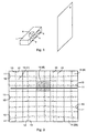
- Fig.1 shows the layout of a CRT projector (1) in relation to a screen (2).
- the projector (1) has three cathode ray tubes, a red (3), a green (4) and a blue (5) tube, each of which projects a picture in the corresponding colour onto the screen (2).
- a camera is present, for example, a CCD (Charge Coupled Device) camera (6) that views the picture projected onto the screen (2).
- CCD Charge Coupled Device
- the red cathode ray tube (3) and the blue cathode ray tube (5) are mechanically set so that the global convergence is already as good as possible, in other words so that the red, green and blue pictures on the screen (2) coincide as accurately as possible.
- the green cathode ray tube (4) is used as reference in this process since it normally delivers the most light and because it is the most central of the three cathode ray tubes (3,4,5). The position of this green cathode ray tube (4) cannot be adjusted mechanically in most cases.
- the projector (1) is delivered to the end-user adjusted in this way.
- the camera (6) has to be able to view each zone to be adjusted which are projected onto the screen (2).
- the camera (6) is centred with respect to both the horizontal and the vertical. This is a mechanical adjustment, which only has to be carried out once for each projector (1).
- Each picture may, for example, comprise different horizontal and vertical lines, for example five horizontal lines (10,11) and five vertical lines (12,13), as represented in Fig. 2.
- the geometry of the picture has no relevance: it may be a line test pattern, but it works equally well with, for example, a piece of text. The sole condition is that the picture information corresponds and is useful for each colour to be adjusted. If test patterns are in fact used, the latter vary both in time and space: thicker contours on the edge (space) to compensate for the light loss, thinner contours (time) whenever very fine tuning is required. To keep the description simple in what follows, a picture built up of horizontal and vertical lines is considered.
- the picture projected onto the screen (2) is divided into, for example, 25 zones 14(i) (where i runs from 1 to 25) (5 vertical x 5 horizontal), a part of the projected picture falling into each zone 14(i).
- a part of a horizontal line (10,11) of the projected picture and a part of a vertical line (12,13) of the projected picture falls into each zone 14(i).
- the locations of the 25 zones 14(i) that must be adjusted are measured using the camera (6).
- the geometrical correspondence between a specific zone 14(i) on the screen (2) and the spot on the camera (6) CCD matrix is stored in a memory. This will later make it possible to digitize only around the useful part of the screen (2), the so-called window 14 (8).
- the adjustment rate of a projector (1) is determined by the sequence of adjustment. To keep the rate sufficiently high, red and blue are adjusted alternately. In this way, the measurement of a blue line can take place while the convergence of a red line is calculated.
- the selection of the algorithms and the manner of their execution also determine the adjustment rate.
- the user instructs the projector (1) to carry out the convergence adjustment.
- the control unit of the projector (1) will set the universal device, which is connected to the projector (1), to a mode which is suitable for carrying out the convergence adjustment.
- this means that the universal device is set to 'window digitization mode', so that it is ready, on a command signal from the control unit of the projector (1), to read in and digitize the picture which the camera (6) sees on the screen (2), and to store only the digitization values of the window 14 (8) indicated by the control unit in the memory.
- the universal device During the adjustment (not only the convergence adjustment, but also the adjustments and other applications discussed later on) it is always possible for the universal device to be set temporarily to another mode, namely an auxiliary mode or secondary mode. Where a specific mode is referred to below, this always means the principal mode necessary for the adjustment or the other application. Controlled switching to secondary modes also determines the adjustment rate and/or the rate of execution of the other applications.
- the background light is first measured in the respective window 14(8).
- the camera (6) is used to scan in the illumination of the screen (2) onto which no picture has been projected.
- the analog signal thus obtained is provided to the universal device of the invention, which device is connected to the control unit of the projector (1) via the interface.
- This signal is digitized in the analog-to-digital converter and the digitized values belonging to the signal in the window 14(8) to be adjusted are stored. Only the required data are stored in the RAM.
- the other data which the control unit of the projector (1) does not need at the instant when the window 14(8) under consideration is being adjusted but which the camera (6) still reads in, are not stored. In this way, the control unit, during the further adjustment, will lose no time in searching for the required data from all the digitized values of the complete picture.
- the intensity of the background light is measured in this way. Later, when the projected pictures are measured, the intensity of the background light from these measurements may be subtracted in order thus to cut out the effect of the background light. Under normal circumstances (not or spatially slowly varying back lighting for example), this is not necessary.
- the green picture comprising the horizontal lines (10) and the vertical lines (12) is built up on the screen after the background light has been measured.
- a vertical line (12) is measured and in the case of a vertical convergence adjustment, a horizontal line (10) is measured.
- the green picture is read in by the camera (6) and forms an analog signal that is provided to the universal device. This signal is digitized in the analog-to-digital converter. Thus digitized values are generated. Only those digitized values coming from the window 14(8) to be adjusted are stored in the memory.
- the red picture comprising horizontal lines (11) and vertical lines (13) is built up on the screen (2) and read in by the camera.
- the analog signal thus formed is once again provided to the universal device.
- the analog-to-digital converter of the latter digitizes the values for the window 14(8) to be adjusted. These digitized values are also stored in the memory.
- Correlation is a mathematical method to find out when two functions are best matched to one another.
- correlation is always a measure of how well two waveforms match.
- a characteristic of correlation is that it is very noise-resistant, since noise does not correlate and therefore will not distort the calculations.
- the measurements and/or results require little filtering and/or averaging. This has a positive effect on the rate and quality of the adjustment.
- the integration from 0 to x is an integration carried out over the measured digitization interval.
- the function C( ⁇ ) has a maximum for a specific value of ⁇ .
- ⁇ 0
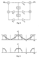
- the correlation is explained visually in Fig.4.
- the two input signals r(x) and g(x) are represented in the figure by a thin continuous line and a dashed line respectively.
- the normalized correlation function is represented in the figure by a thick continuous line. Both functions r(x) and g(x) are shifted 9 time units with respect to each other. This leads to a maximum in the correlation function at 9, as can be calculated easily using the discrete form of formula (1):
- the correlation calculation can also be carried out in two dimensions, so that the convergence error is measured both in the horizontal and the vertical direction at the same time.
- each zone 14(i) has its own adjustment and these adjustments can be quite different from zone to zone.
- B 0 is a value between 0 and 127 (if a 7-bit convergence adjustment system is being used), which causes a shift to the line to be adjusted in zone 14(j).
- B 1 is a value between 0 and 127, which causes a shift to the line to be adjusted in zone 14(j+1).
- the adjustment of B 0 also causes a convergence error in zone 14 (j+1) and vice versa. This is the effect of the zones on one another. This effect will be eliminated by working with linked zones.
- index I 0 is a function of the adjustments B 0 and B 1 .
- the accuracy of this calculation method naturally depends on the determination of the parameters a, b, c, d, e and f. These first have to be measured.
- the parameters a, b and c define a plane. They can thus be determined by initially measuring three points. For this purpose, the index I 0 is measured for three different pairs ( B 0 , B 1 ). This provides a mathematical model for the convergence error in zone 0 as a function of the adjustment in zone 14(j) and in zone 14(j+1).
- the accuracy of this model is determined by the accuracy of the measurements for determining the plane. If there is one deviating measurement amongst these, the complete model remains usable per se. It is precisely those measurements which do not lie within the expected pattern which steer the model in the right direction.
- the linkage can be extended to a plurality of zones.
- the horizontal and vertical linkage can occur together.
- Signals are derived from the value obtained for the correlation, which gives the relative distance between the two pictures which are to converge with one another, which signals are sent to the hardware which is responsible for the convergence adjustment and which shifts one of the signals towards the other.
- correlation of two signals corresponds to a simple multiplication: ⁇ 1 ( t ) ⁇ 2 ( t ) ⁇ V 1 *( ⁇ ) V 2 ( ⁇ ) ⁇ 1 *( t ) ⁇ 2 ( t ) ⁇ V 1 *( ⁇ ) ⁇ V 2 ( ⁇ ) where ⁇ stands for correlation and * for the complex conjugate of the corresponding data series.
- the Discrete Fourier Transform is one of the most important tools in modern applications in digital signal processing.
- the DFT of a sequence x(n) with a length N is defined as:
- the complete computational algorithm can be split up into a repeated application of an elementary transformation known as 'butterfly' (Cooley-Tukey) form. Examples of FFT may be found in the literature.
- the rate can be increased further without using a special co-processor.
- the Fourier cosine and sine values for example, can be retreived from a look-up table so that they do not have to be recalculated each time.
- the measured data are optionally filtered.
- Example 1 spatial filtering (for example, 'neighbourhood averaging')
- y ( n ) Ax ( n -2) + Bx ( n -1) + Cx ( n ) + Dx ( n +1) + Ex ( n +2)
- This filter describes a kind of averaging of the incoming pixels. This averaging cannot be done in real time, as use is made of future samples. This means that all the input data must first be read in and then the calculation can be carried out.
- the aforementioned example shows a calculation in one dimension.
- the filtering can also occur in two dimensions.
- T 1 and T 2 are only dependent on signal values at the times k-1 and k-2 (and not on signal values at time k), we can already calculate these values in the time interval between k-1 and k and store them.
- This filter technique can be applied in real time, but demands a great deal of calculation time, particularly when a higher order filter is used (cascading of different filter sections of a lower order). Special provisions must be made to avoid overflow during the calculating - thus a special scaling must be implemented.
- SINC convolution of the original signal in the time domain provides very good performance in terms of quality.
- the disadvantage is that SINC convolution demands a great deal of computational time. These computations cannot be done in real time.
- a filter in the frequency domain, which is much easier to do than in the time domain.
- the objective of a filter is, after all, to eliminate high-frequency, unwanted frequency components.
- the Fourier transform of the input data is calculated, as shown in the block diagram in Fig. 3, only the unwanted frequencies have to be annulled.
- Fig. 6 where the amplitude spectrum is given as a function of the frequency.
- 'fs' stands for the Shannon-Nyquist frequency.
- Fig. 6a shows an unfiltered spectrum, as well as a low-pass filter.
- Fig. 6 b shows the resulting spectrum after passing through the said low-pass filter.
- the annulment speeds up the calculation of the inverse Fourier transform.
- Table 3 shows a possible row of interpolated values based on the values from Table 1.
- the CCD camera (6) takes its pictures at a field frequency of, for example, 50 Hz, but this frequency has no relationship with the frequency of the projected source. Consequently, it is possible that the window 14(8) may lie at a specific instant in the 'black', non-scanned part.
- the curves are actual exponentials whose time constants are directly controlled through the value of K .
- K 0, the new measurements are not taken into account and only the old estimations remain (in a manner of speaking an infinite filter effect).
- K 1, on the other hand, there is no need for filtering: the new estimate is then always directly equated to the new measurements.
- the chief advantage of this method is its immunity to incorrect measurements (for example the source of lines). These measurements are smoothed instead of an averaging being carried out on each measurement.
- the calculated digitized values are always multiplied by the gain factor A. This is possible since these values have already been in the filter and therefore there is a smaller chance that the noise will be amplified, since the latter is eliminated through the effect of the filter.
- the level of useful information thus rises, or in other words: the signal-to-noise ratio is enhanced in a mathematical way.
- a scale marker can be projected onto the screen (2) to see clearly how well the convergence of a zone or of the complete picture has been adjusted.
- the accompanying control unit can act as a gate in order to send this information, for example via an RS232 channel, to a PC, where it can be read out.
- the user gives an instruction to the projector (1) to carry out the geometry adjustment.
- the control unit of the projector (1) will set the universal device (connected to the projector (1)) into a mode suitable for carrying out geometry adjustment.
- this means that the universal device is set to 'window digitization mode', i.e. ready, on a command signal from the control unit of the projector (1), to read and digitize the picture that the camera (6) views on the screen (2), and to store only the digitized values from the window 14(8) indicated by the control unit in memory.
- reference values for the geometry are stored, which values indicate, for example, the left- and right-hand top and bottom corners, as well as the centre of the picture.
- the picture on which adjustment is to be made is therefore not another picture projected onto the screen (2) but consists of a number of reference values stored in the memory, input by a user or indicated via a laser pointer (see also point 10.)
- the reference can also be a fixed frame arranged onto the screen (2). Correlation is used to adjust the picture to these reference values, preferably using the 'linked' zones principle.
- a scale marker can be projected onto the screen (2) to see clearly how well the geometry of a zone or of the complet picture has been adjusted.
- the accompanying control unit can act as a gate in order to send this information, for example via an RS232 channel, to a PC, where it can be read out.
- the projector (1) control unit again sets the universal device to window digitization mode.
- the adjustment zones 14(i) are again determined, in the same way as described above.
- the correspondence between the location of these zones 14(i) on the screen (2) and the camera (6) pixels is measured, or the corresponding values are read in f rom a memory.
- the camera (6) views the picture projected onto the screen (2) and forms an analog signal, which is fed to the universal device. This analog signal is converted into digitized values via analog-to-digital conversion.
- the focus of the picture is adjusted for the various linked zones 14(i) by constructing a mathematical model based on variance calculations in the form of a histogram or spectrum evaluation.
- Histograms are frequently used for measurements.
- the digital contrast of a picture is derived using the distribution of the grey-scale values. When this distribution is concentrated around a certain level, then the contrast is clearly low. The contrast of a picture as a whole can be read from this histogram.
- the average intensity of a picture is determined from the following formula: where N is the number of different grey-scale values occurring, X(n) is the number of pixels in the measured picture with intensity n.
- V ( x ) E ( X 2 ) - ( E ( X )) 2
- contrast is taken as the square root of the variance.
- the number obtained is a measure of the optimum focus value of the picture, for this gives a measure of the difference in grey-scale values between a pixel X and the average grey-scale value.
- a measure of the picture sharpness can be obtained not only from the grey-scale value histogram calculations, but also from spectrum evaluation.
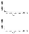
- a square wave is a representation of the ideal test pattern, a sinusoidal curve a representation of the measured test pattern.
- the Fourier transform of the square wave is as shown in Fig.13, while the Fourier transform of the sinusoidal curve is as shown in Fig.14.
- a possible measure for the sharpness can, for example, be the number of high-frequency components, depending on what level of sharpness is desired by the user.
- the variance in the spectral components can also be regarded as a measure of the sharpness.
- Signals which are sent to the hardware responsible for focus adjustment concerning the adjustment zones 14(i) are derived from the relative values ultimately obtained for the optimum focus value in each of the adjustment zones 14(i).
- the astigmatism in the centre of the picture is adjusted via mechanical shift rings around the picture tube. For the time being, this adjustment cannot yet be done automatically, but the measurements can give the user who is adjusting the device an indication of how well the adjustment has been done, until the measurements 'state' that the optimum focus value has been attained by this manual adjustment.
- the universal device is again set to 'window digitization mode' for this method.
- the adjustment zones 14(i) are determined and the corresponding coordinates on the camera (6) are fetched.
- Camera (6) views the picture, which is sent to the universal device and forms an analog signal that is converted into digitized values in the analog-to-digital converter.
- the first two methods are as described with regard to automatic focus adjustment.
- the central point that is to say the 'centre of the picture', lies at coordinates ( b 10 , b 01 ). Let us then consider a shift corresponding to ( x - b 10 , y - b 01 ). This amounts to the probability density distribution of the picture being centred around the central point. It is in fact reliably centred because this translation makes the first order moments zero, in other words the central point comes to lie at the origin.
- measurements derived from astigmatism using the aforementioned method can provide valuable information to the user: for example, a scale marker may be projected onto the screen (2) giving an indication of the pixel quality in specific areas.
- the accompanying control unit can act as a gate to send this information via, for example, an RS232 channel to a PC, where it may be read out.
- the aforementioned adjustment can only be applied to CRT projectors.
- the universal device is again put into the 'window digitization mode'.
- calibration values for the camera (6) relating to the intensity, for the colour or colours to be controlled are fetched from the memory or measured, after which these values can be entered into the mathematical model.
- the zones 14(i) are determined as described above.
- Intensity measurements are made giving a measure for the relative intensity for a well-defined or known control relating to the colour or colours to be adjusted.
- a model is constructed. Optimum values are determined by intensity measurements. These are entered into the model. Should a residual error still remain, then the model is improved using an iterative process.
- signals are derived which are sent to the hardware responsible for contrast-modulation control relating to the adjustment zones.
- a scale marker can be projected onto the screen (2) or the accompanying control unit can act as a gate in order to send this information via, for example, an RS232 channel to a PC where it then can be read out.
- the automatic adjustment of the gamma correction takes place in a similar way to the automatic adjustment of the contrast modulation.
- a measure for the relative intensity is determined and from this signals are derived which are sent to the hardware responsible for gamma-correction control.
- a scale marker can be projected onto the screen (2) or the accompanying control unit can act as a gate in order to send this information via, for example, an RS232 channel to a PC where it then can be read out.
- Soft edge has to be adjusted whenever two or more projectors project onto the screen pictures which contact one another. In the boundary area, the pictures will overlap a little and therefore we obtain double the intensity. It is precisely in that area that each of the pictures must be subjected to an intensity drop so that when the pictures overlap the sum of the intensities is the same as the intensity in the rest of the picture.
- the automatic adjustment occurs in the same way as the contrast-modulation adjustment, except that it is carried out at the edge of the picture.
- the wire-free transmission of information described in point 13 can be used in the adjustment of soft edge.
- a scale marker can be projected onto the screen (2) or the accompanying control unit can act as a gate in order to send this information via, for example, an RS232 channel to a PC, where it then can be read out.
- one or more of the operations described for automatic convergence control namely exponential smoothing, transformation, filtering and/or interpolation, can be applied to the digitized values.
- Wire-free transmission of information described in point 13 can be used in the adjustment of adjacent and/or overlapping geometry.
- a scale marker can be projected onto the screen (2) or the accompanying control unit can act as a gate in order to send this information via, for example, an RS232 channel to a PC, where it can be read out.
- the universal device is put into a mode such that it is able to digitize continuously.
- a control unit transfers these data via any form of communication means (for example via RS232) to a PC, where these digital data are processed.
- the universal device is put into 'peak detection mode' for implementation as a peak detector.
- a camera (6) views the picture projected onto the screen (2) and the analog signal which is thus obtained is constantly digitized without values being stored in the RAM. Points with a high light intensity are continuously being sought.
- the peak detector can be used for example to indicate references for geometry adjustment using for example a laser pointer. These are measured by the peak detector and the corresponding relative reference coordinates are sent to the control unit.
- the peak detector may likewise be used for the implementation of a mouse tracker for a laser pointer. For this, the same procedure is adopted. If a point with high intensity is detected, the accompanying control unit is informed of this and the corresponding XY coordinates of the tops of the peaks are sent, for example, to a PC in order to make the mouse pointer track. Instead of allowing the PC to make the mouse pointer track, it is also possible to command the projector (1) itself to project a character onto the location having those coordinates.
- the universal device is put into a mode so as to operate as a memory expansion or specific auxiliary control unit for the existing control unit. In this configuration the analog-to-digital converter is not used.
- the correlation calculations of the aforementioned methods can be carried out by the device, as a result of which the control unit gains additional time to execute other operations. In this way one gains adjustment speed.
- the universal device is put into a mode so that, for example, it can be used for testing. Different test modes are possible according to the tests to be carried out.
- the memory In self-test mode, the memory is tested for data loss and the short-circuiting of data or of address lines. Also the analog-to-digital converter and all other integrated circuits may be tested in this way.
- the device itself must be in good condition before reliable measurements and calculations can be made.
- Part of the operation of the accompanying control unit of the projector (1) can also be tested via the universal device provided it is set in the appropriate mode.
- the universal device is put into a mode so that it is suitable for signal analysis. If an analog signal is applied to the pin of the device, the latter can analyse and check this signal for specific characteristics.
- Two projectors (1) which are in each other's field of view with regard to the camera (6) can communicate with each other via light codes instead of via physical means such as cables.
- These light codes can be a kind of bar code, which are projected by one projector (1) onto the screen (2) after which they are detected by the other.
- Each bar code or sequence of bar codes contains an instruction.
- the detecting projector (1) carries out this instruction and can also in turn project light codes onto the screen (2), which can be scanned by the other projector (1) and the corresponding instruction can be carried out.
- Line detection is the measurement principle used to find the location of the bar codes.
- the object of this principle is to find a limit value.
- the method consists in drawing up the normalized grey-scale value histogram for the digitized values. Normalized is understood to mean that the grey-scale values lie between 0 and 1. Then a confidence interval relating to the grey-scale values is selected containing for example 90% of the grey-scale values.
- the grey-scale value central point is calculated (indicated by O in Fig. 16) using the grey-scale values located within the confidence interval - this being a good value for the average background intensity. This value can be used to derive the limit value.
- the limit value has a power between 0 and 1 of the previously calculated grey-scale value central point, for example the square root.
- Each normalized digitized value located above this limit value indicates the presence of a line. The width and the coordinates of the line can be derived from the original series of digitized values.
- This method can also be applied in two dimensions.
- the light codes may also be sequential intensity variations, as a result of which the use of a test picture generator is rendered superfluous.
- the measurement principle applied in intensity variations is relative intensity measurements.
- the transmission of information between a plurality of projectors (1) can be used for the adjustment of overlapping or adjacent geometry, for the adjustment of soft edge or for simple data transfer.
- the transmission of information is always necessary if it is necessary to control the other projector (1) in order to obtain the adjustment correctly.
- the universal device is put into a mode so as to operate as a teletext decoder.
- the analog-to-digital converter is used to convert the analog video signal which contains teletext information into digitized values via analog-to-digital conversion. From these digitized values, the accompanying control unit or the universal device itself can extract the teletext information.
- RS232 decoding or if the signal which is applied to the pin originates from an IR receiver, the universal device can be set in a mode such that it is able to decode different IR codes, for example codes output by a remote control.
Landscapes
- Engineering & Computer Science (AREA)
- Multimedia (AREA)
- Signal Processing (AREA)
- Health & Medical Sciences (AREA)
- Biomedical Technology (AREA)
- General Health & Medical Sciences (AREA)
- Projection Apparatus (AREA)
- Video Image Reproduction Devices For Color Tv Systems (AREA)
- Controls And Circuits For Display Device (AREA)
- Overhead Projectors And Projection Screens (AREA)
Applications Claiming Priority (3)
| Application Number | Priority Date | Filing Date | Title |
|---|---|---|---|
| BE9600536 | 1996-06-12 | ||
| BE9600536A BE1010346A5 (nl) | 1996-06-12 | 1996-06-12 | Niet expliciet toepassingsgericht apparaat en gebruik ervan voor de automatische afregeling van een projector. |
| PCT/BE1997/000071 WO1997048232A1 (en) | 1996-06-12 | 1997-06-12 | Universal device and use thereof for the automatic adjustment of a projector |
Publications (2)
| Publication Number | Publication Date |
|---|---|
| EP0904659A1 EP0904659A1 (en) | 1999-03-31 |
| EP0904659B1 true EP0904659B1 (en) | 2003-11-26 |
Family
ID=3889803
Family Applications (1)
| Application Number | Title | Priority Date | Filing Date |
|---|---|---|---|
| EP97925796A Expired - Lifetime EP0904659B1 (en) | 1996-06-12 | 1997-06-12 | Projector with a circuit and method for the automatic adjustment of said projector |
Country Status (8)
Families Citing this family (45)
| Publication number | Priority date | Publication date | Assignee | Title |
|---|---|---|---|---|
| US5818597A (en) * | 1996-10-22 | 1998-10-06 | Ultra Stereo Labs, Inc. | Projection system visual characteristics analyzer |
| BE1011580A5 (nl) * | 1997-12-01 | 1999-11-09 | Barco Naamloze Vennootschap | Werkwijze en inrichting voor het regelen van een of meer projectoren. |
| US6198514B1 (en) | 1998-02-27 | 2001-03-06 | Apple Computer, Inc. | Color misconvergence measurement using a common monochrome image |
| KR100414083B1 (ko) * | 1999-12-18 | 2004-01-07 | 엘지전자 주식회사 | 영상왜곡 보정방법 및 이를 이용한 영상표시기기 |
| US6618076B1 (en) * | 1999-12-23 | 2003-09-09 | Justsystem Corporation | Method and apparatus for calibrating projector-camera system |
| CN1154082C (zh) * | 2000-08-28 | 2004-06-16 | 精工爱普生株式会社 | 环境适应型的图像显示系统和图像处理方法 |
| US6995810B2 (en) * | 2000-11-30 | 2006-02-07 | Texas Instruments Incorporated | Method and system for automated convergence and focus verification of projected images |
| JP4185678B2 (ja) * | 2001-06-08 | 2008-11-26 | 株式会社日立製作所 | 液晶表示装置 |
| US6527395B1 (en) * | 2001-12-10 | 2003-03-04 | Mitsubishi Electric Research Laboratories, Inc. | Method for calibrating a projector with a camera |
| KR100422295B1 (ko) * | 2002-05-18 | 2004-03-11 | 엘지.필립스 엘시디 주식회사 | 디스플레이 장치의 화질 분석 방법 및 시스템 |
| US6888564B2 (en) * | 2002-05-24 | 2005-05-03 | Koninklijke Philips Electronics N.V. | Method and system for estimating sharpness metrics based on local edge kurtosis |
| US7215362B2 (en) * | 2002-10-31 | 2007-05-08 | Fraunhofer-Gesellschaft Zur Foerderung Der Angewandten Forschung E.V. | Auto-calibration of multi-projector systems |
| ITTO20021069A1 (it) * | 2002-12-06 | 2004-06-07 | Sim2 Multimedia Spa | Metodo di regolazione elettronica della geometria in un videoproiettore utilizzato in retroproiezione e videoproiettore utilizzante tale metodo. |
| US7210798B2 (en) * | 2003-01-17 | 2007-05-01 | High End Systems Inc. | Image projection lighting device and control system |
| US7184054B2 (en) * | 2003-01-21 | 2007-02-27 | Hewlett-Packard Development Company, L.P. | Correction of a projected image based on a reflected image |
| US20040165068A1 (en) * | 2003-02-25 | 2004-08-26 | Jane Rone Fue | Projector color calibration device and method |
| CA2464569A1 (en) * | 2003-04-16 | 2004-10-16 | Universite De Montreal | Single or multi-projector for arbitrary surfaces without calibration nor reconstruction |
| US7097311B2 (en) * | 2003-04-19 | 2006-08-29 | University Of Kentucky Research Foundation | Super-resolution overlay in multi-projector displays |
| US7478754B2 (en) * | 2003-08-25 | 2009-01-20 | Symbol Technologies, Inc. | Axial chromatic aberration auto-focusing system and method |
| JP2007508732A (ja) * | 2003-09-30 | 2007-04-05 | コーニンクレッカ フィリップス エレクトロニクス エヌ ヴィ | 画像投射装置 |
| US7196741B2 (en) * | 2003-10-15 | 2007-03-27 | Mitsubishi Digital Electronics America, Inc. | Automatic image convergence for projection television systems |
| FI115947B (fi) * | 2004-02-25 | 2005-08-15 | Nokia Corp | Elektroninen laite ja menetelmä elektronisessa laitteessa kuvainformaation muodostamiseksi sekä ohjelmatuote menetelmän toteuttamiseksi |
| US7683881B2 (en) * | 2004-05-24 | 2010-03-23 | Keytec, Inc. | Visual input pointing device for interactive display system |
| US7490942B2 (en) * | 2004-11-23 | 2009-02-17 | Hewlett-Packard Development Company, L.P. | Projector with automatic focusing assistance |
| US20070030452A1 (en) * | 2005-08-08 | 2007-02-08 | N-Lighten Technologies | Image adaptation system and method |
| US20070074040A1 (en) * | 2005-09-29 | 2007-03-29 | Nokia Corporation | Online authorization using biometric and digital signature schemes |
| US20070182847A1 (en) * | 2006-02-09 | 2007-08-09 | Canon Kabushiki Kaisha | Projection display apparatus |
| US7880719B2 (en) * | 2006-03-23 | 2011-02-01 | International Business Machines Corporation | Recognition and capture of whiteboard markups in relation to a projected image |
| US7658498B2 (en) * | 2006-07-13 | 2010-02-09 | Dell Products, Inc. | System and method for automated display orientation detection and compensation |
| US7677737B2 (en) * | 2006-08-17 | 2010-03-16 | Sony Ericsson Mobile Communications Ab | Projector adaptation for self-calibration |
| US7865332B2 (en) * | 2007-01-08 | 2011-01-04 | International Business Machines Corporation | Scaled exponential smoothing for real time histogram |
| FR2914099B1 (fr) * | 2007-03-22 | 2013-04-05 | Eads Test & Services | Systeme de test universel apte a controler une pluralite de parametres relatifs au fonctionnement de dispositif de presentation d'informations optoelectroniques de types varies |
| JP4687773B2 (ja) * | 2008-11-17 | 2011-05-25 | セイコーエプソン株式会社 | プロジェクションシステム |
| US8773529B2 (en) * | 2009-06-04 | 2014-07-08 | Sypro Optics Gmbh | Projector with automatic focusing and illustration procedure |
| US8953049B2 (en) * | 2010-11-24 | 2015-02-10 | Echostar Ukraine L.L.C. | Television receiver—projector compensating optical properties of projection surface |
| US8531474B2 (en) | 2011-11-11 | 2013-09-10 | Sharp Laboratories Of America, Inc. | Methods, systems and apparatus for jointly calibrating multiple displays in a display ensemble |
| KR20150115455A (ko) | 2014-04-04 | 2015-10-14 | 삼성전자주식회사 | 휴대단말기의 프로젝터 초점 제어 방법 및 장치 |
| US20170094238A1 (en) * | 2015-09-30 | 2017-03-30 | Hand Held Products, Inc. | Self-calibrating projection apparatus and process |
| US10694160B2 (en) | 2018-11-20 | 2020-06-23 | Disney Enterprises, Inc. | Channel based projector calibration |
| US12185585B2 (en) | 2022-12-19 | 2024-12-31 | Stereyo Bv | Active matrix display, system, and method having an additional transistor that discharges a storage capacitor within pixel circuits, at least one pixel circuit driven by a drive circuit resides physical within another drive circuit, and/or off-to-on time of scan signals are set in relation to an operation of a camera recording the display |
| US12100363B2 (en) | 2022-12-19 | 2024-09-24 | Stereyo Bv | Configurations, methods, and devices for improved visual performance of a light-emitting element display and/or a camera recording an image from the display |
| US12119330B2 (en) | 2022-12-19 | 2024-10-15 | Stereyo Bv | Configurations, methods, and devices for improved visual performance of a light-emitting element display and/or a camera recording an image from the display |
| US12080224B2 (en) | 2022-12-19 | 2024-09-03 | Stereyo Bv | Configurations, methods, and devices for improved visual performance of a light-emitting element display and/or a camera recording an image from the display |
| US12112695B2 (en) | 2022-12-19 | 2024-10-08 | Stereyo Bv | Display systems and methods with multiple and/or adaptive primary colors |
| US12199079B2 (en) | 2022-12-19 | 2025-01-14 | Stereyo Bv | Configurations, methods, and devices for improved visual performance of a light-emitting element display and/or a camera recording an image from the display |
Family Cites Families (11)
| Publication number | Priority date | Publication date | Assignee | Title |
|---|---|---|---|---|
| FR2652695B1 (fr) * | 1989-10-03 | 1993-04-16 | Thomson Csf | Procede et dispositif de visualisation d'images, a correction automatique de defauts par contre-reaction. |
| JPH03245687A (ja) * | 1990-02-23 | 1991-11-01 | Canon Inc | 投射型ディスプレイ |
| FR2660090B1 (fr) * | 1990-03-23 | 1994-07-29 | Thomson Csf | Dispositif de visualisation par projection a boucle de contre-reaction pour la correction de l'ensemble des defauts de l'image projetee. |
| JPH03280677A (ja) * | 1990-03-28 | 1991-12-11 | Toshiba Corp | マルチ映像表示装置の直流伝送量設定回路 |
| US5136390A (en) * | 1990-11-05 | 1992-08-04 | Metavision Corporation | Adjustable multiple image display smoothing method and apparatus |
| DE59009699D1 (de) * | 1990-11-06 | 1995-10-26 | Itt Ind Gmbh Deutsche | Projektionsfernsehsystem. |
| JP3409330B2 (ja) * | 1991-02-08 | 2003-05-26 | ソニー株式会社 | 投射型表示装置の調整装置および調整方法 |
| US5345262A (en) * | 1992-07-31 | 1994-09-06 | Hughes-Jvc Technology Corporation | Automatic convergence system for color video projector |
| DE69422074D1 (de) * | 1993-03-17 | 2000-01-20 | Matsushita Electric Ind Co Ltd | Bildkorrekturvorrichtung |
| KR0141232B1 (ko) * | 1993-08-31 | 1998-06-15 | 김광호 | 자동 디지탈 콘버젼스 보정방법 및 장치 |
| US5432404A (en) * | 1993-12-10 | 1995-07-11 | Hitachi, Ltd. | Apparatus for detecting a geometric distortion of an image on a display device |
-
1996
- 1996-06-12 BE BE9600536A patent/BE1010346A5/nl not_active IP Right Cessation
-
1997
- 1997-06-12 AU AU30853/97A patent/AU3085397A/en not_active Abandoned
- 1997-06-12 WO PCT/BE1997/000071 patent/WO1997048232A1/en active IP Right Grant
- 1997-06-12 DE DE69726421T patent/DE69726421T2/de not_active Expired - Fee Related
- 1997-06-12 AT AT97925796T patent/ATE255313T1/de not_active IP Right Cessation
- 1997-06-12 JP JP50958397A patent/JP2001504644A/ja not_active Ceased
- 1997-06-12 EP EP97925796A patent/EP0904659B1/en not_active Expired - Lifetime
-
1998
- 1998-12-11 US US09/209,415 patent/US6483555B1/en not_active Expired - Lifetime
Also Published As
| Publication number | Publication date |
|---|---|
| DE69726421T2 (de) | 2004-09-02 |
| JP2001504644A (ja) | 2001-04-03 |
| BE1010346A5 (nl) | 1998-06-02 |
| US6483555B1 (en) | 2002-11-19 |
| AU3085397A (en) | 1998-01-07 |
| WO1997048232A1 (en) | 1997-12-18 |
| EP0904659A1 (en) | 1999-03-31 |
| ATE255313T1 (de) | 2003-12-15 |
| DE69726421D1 (de) | 2004-01-08 |
Similar Documents
| Publication | Publication Date | Title |
|---|---|---|
| EP0904659B1 (en) | Projector with a circuit and method for the automatic adjustment of said projector | |
| CN110310237B (zh) | 去除图像摩尔纹、显示面板子像素点亮度测量、Mura缺陷修复的方法及系统 | |
| EP0274447B1 (en) | Image recorder having automatic alignment method and apparatus | |
| US5699440A (en) | Method and system for testing the performance of at least one electro-optical test device | |
| US3932733A (en) | Automatic focusing of an optical system | |
| US5200815A (en) | Convergence correction apparatus for a video projection system | |
| EP0511754B1 (en) | Apparatus and method for descreening | |
| CN101136192B (zh) | 用于显示几何和色彩的自动校准和校正的系统和方法 | |
| US6115022A (en) | Method and apparatus for adjusting multiple projected raster images | |
| EP0518185B1 (en) | Cross correlation image sensor alignment system | |
| Martinez et al. | High-resolution colorimetric imaging of paintings | |
| EP0878970A2 (en) | Imager registration error and chromatic aberration measurement system for a video camera | |
| US20040008267A1 (en) | Method and apparatus for generating images used in extended range image composition | |
| JPH0595509A (ja) | 画像撮影装置により観察される被写界内の深度に関する情報の要素を獲得する方法及び装置 | |
| US6885801B1 (en) | Enhancement of fiber based images | |
| US4979225A (en) | Method and apparatus for detecting corresponding regions between picture images | |
| US5852671A (en) | Method for reconstructing a curved surface of a subject and an apparatus for reconstructing a curved surface of a subject | |
| JPH09116809A (ja) | テレビフィルム走査における画像ステディネスエラーの補正方法及びテレビ画像内の所定の画像対象物のモーションシーケンスの変化方法並びに前記補正方法を実施するための装置 | |
| JPH10200911A (ja) | カラーテレビジョンカメラにおけるレジストレーション誤差を自動的に補正するシステムおよび方法 | |
| Shafer | Automation and calibration for robot vision systems | |
| Egorov et al. | Efficiency Evaluation of Noise Based Camera Measurements Algorithms | |
| SU1109945A1 (ru) | Способ формировани сигнала дл коррекции искажений телевизионного изображени и устройство дл его реализации | |
| JP3453177B2 (ja) | 複数の画像間の位置の差を測定する方法 | |
| WO2025109051A1 (en) | Method for generating a volumetric image of a sample and light sheet microscope | |
| Lewis | Modulation transfer function measurement for solid-state intensified cameras |
Legal Events
| Date | Code | Title | Description |
|---|---|---|---|
| PUAI | Public reference made under article 153(3) epc to a published international application that has entered the european phase |
Free format text: ORIGINAL CODE: 0009012 |
|
| 17P | Request for examination filed |
Effective date: 19990111 |
|
| AK | Designated contracting states |
Kind code of ref document: A1 Designated state(s): AT BE CH DE DK ES FI FR GB GR IE IT LI LU MC NL PT SE |
|
| 17Q | First examination report despatched |
Effective date: 19990705 |
|
| GRAH | Despatch of communication of intention to grant a patent |
Free format text: ORIGINAL CODE: EPIDOS IGRA |
|
| RTI1 | Title (correction) |
Free format text: PROJECTOR WITH A CIRCUIT AND METHOD FOR THE AUTOMATIC ADJUSTMENT OF SAID PROJECTOR |
|
| RTI1 | Title (correction) |
Free format text: PROJECTOR WITH A CIRCUIT AND METHOD FOR THE AUTOMATIC ADJUSTMENT OF SAID PROJECTOR |
|
| GRAS | Grant fee paid |
Free format text: ORIGINAL CODE: EPIDOSNIGR3 |
|
| GRAA | (expected) grant |
Free format text: ORIGINAL CODE: 0009210 |
|
| AK | Designated contracting states |
Kind code of ref document: B1 Designated state(s): AT BE CH DE DK ES FI FR GB GR IE IT LI LU MC NL PT SE |
|
| PG25 | Lapsed in a contracting state [announced via postgrant information from national office to epo] |
Ref country code: NL Free format text: LAPSE BECAUSE OF FAILURE TO SUBMIT A TRANSLATION OF THE DESCRIPTION OR TO PAY THE FEE WITHIN THE PRESCRIBED TIME-LIMIT Effective date: 20031126 Ref country code: LI Free format text: LAPSE BECAUSE OF FAILURE TO SUBMIT A TRANSLATION OF THE DESCRIPTION OR TO PAY THE FEE WITHIN THE PRESCRIBED TIME-LIMIT Effective date: 20031126 Ref country code: FI Free format text: LAPSE BECAUSE OF FAILURE TO SUBMIT A TRANSLATION OF THE DESCRIPTION OR TO PAY THE FEE WITHIN THE PRESCRIBED TIME-LIMIT Effective date: 20031126 Ref country code: CH Free format text: LAPSE BECAUSE OF FAILURE TO SUBMIT A TRANSLATION OF THE DESCRIPTION OR TO PAY THE FEE WITHIN THE PRESCRIBED TIME-LIMIT Effective date: 20031126 Ref country code: AT Free format text: LAPSE BECAUSE OF FAILURE TO SUBMIT A TRANSLATION OF THE DESCRIPTION OR TO PAY THE FEE WITHIN THE PRESCRIBED TIME-LIMIT Effective date: 20031126 |
|
| REG | Reference to a national code |
Ref country code: GB Ref legal event code: FG4D |
|
| REG | Reference to a national code |
Ref country code: CH Ref legal event code: EP |
|
| REF | Corresponds to: |
Ref document number: 69726421 Country of ref document: DE Date of ref document: 20040108 Kind code of ref document: P |
|
| REG | Reference to a national code |
Ref country code: IE Ref legal event code: FG4D |
|
| PG25 | Lapsed in a contracting state [announced via postgrant information from national office to epo] |
Ref country code: SE Free format text: LAPSE BECAUSE OF FAILURE TO SUBMIT A TRANSLATION OF THE DESCRIPTION OR TO PAY THE FEE WITHIN THE PRESCRIBED TIME-LIMIT Effective date: 20040226 Ref country code: GR Free format text: LAPSE BECAUSE OF FAILURE TO SUBMIT A TRANSLATION OF THE DESCRIPTION OR TO PAY THE FEE WITHIN THE PRESCRIBED TIME-LIMIT Effective date: 20040226 Ref country code: DK Free format text: LAPSE BECAUSE OF FAILURE TO SUBMIT A TRANSLATION OF THE DESCRIPTION OR TO PAY THE FEE WITHIN THE PRESCRIBED TIME-LIMIT Effective date: 20040226 |
|
| RAP2 | Party data changed (patent owner data changed or rights of a patent transferred) |
Owner name: BARCO N.V. |
|
| PG25 | Lapsed in a contracting state [announced via postgrant information from national office to epo] |
Ref country code: ES Free format text: LAPSE BECAUSE OF FAILURE TO SUBMIT A TRANSLATION OF THE DESCRIPTION OR TO PAY THE FEE WITHIN THE PRESCRIBED TIME-LIMIT Effective date: 20040309 |
|
| REG | Reference to a national code |
Ref country code: GB Ref legal event code: 732E |
|
| NLT2 | Nl: modifications (of names), taken from the european patent patent bulletin |
Owner name: BARCO N.V. |
|
| NLV1 | Nl: lapsed or annulled due to failure to fulfill the requirements of art. 29p and 29m of the patents act | ||
| PG25 | Lapsed in a contracting state [announced via postgrant information from national office to epo] |
Ref country code: LU Free format text: LAPSE BECAUSE OF NON-PAYMENT OF DUE FEES Effective date: 20040612 |
|
| PG25 | Lapsed in a contracting state [announced via postgrant information from national office to epo] |
Ref country code: IE Free format text: LAPSE BECAUSE OF NON-PAYMENT OF DUE FEES Effective date: 20040614 |
|
| REG | Reference to a national code |
Ref country code: CH Ref legal event code: PL |
|
| PG25 | Lapsed in a contracting state [announced via postgrant information from national office to epo] |
Ref country code: MC Free format text: LAPSE BECAUSE OF NON-PAYMENT OF DUE FEES Effective date: 20040630 |
|
| ET | Fr: translation filed | ||
| PLBE | No opposition filed within time limit |
Free format text: ORIGINAL CODE: 0009261 |
|
| STAA | Information on the status of an ep patent application or granted ep patent |
Free format text: STATUS: NO OPPOSITION FILED WITHIN TIME LIMIT |
|
| 26N | No opposition filed |
Effective date: 20040827 |
|
| REG | Reference to a national code |
Ref country code: IE Ref legal event code: MM4A |
|
| PG25 | Lapsed in a contracting state [announced via postgrant information from national office to epo] |
Ref country code: PT Free format text: LAPSE BECAUSE OF NON-PAYMENT OF DUE FEES Effective date: 20040426 |
|
| PGFP | Annual fee paid to national office [announced via postgrant information from national office to epo] |
Ref country code: IT Payment date: 20080625 Year of fee payment: 12 |
|
| PGFP | Annual fee paid to national office [announced via postgrant information from national office to epo] |
Ref country code: DE Payment date: 20080620 Year of fee payment: 12 |
|
| PGFP | Annual fee paid to national office [announced via postgrant information from national office to epo] |
Ref country code: FR Payment date: 20080613 Year of fee payment: 12 |
|
| PGFP | Annual fee paid to national office [announced via postgrant information from national office to epo] |
Ref country code: GB Payment date: 20080620 Year of fee payment: 12 |
|
| PGFP | Annual fee paid to national office [announced via postgrant information from national office to epo] |
Ref country code: BE Payment date: 20080728 Year of fee payment: 12 |
|
| BERE | Be: lapsed |
Owner name: *BARCO N.V. Effective date: 20090630 |
|
| GBPC | Gb: european patent ceased through non-payment of renewal fee |
Effective date: 20090612 |
|
| REG | Reference to a national code |
Ref country code: FR Ref legal event code: ST Effective date: 20100226 |
|
| PG25 | Lapsed in a contracting state [announced via postgrant information from national office to epo] |
Ref country code: FR Free format text: LAPSE BECAUSE OF NON-PAYMENT OF DUE FEES Effective date: 20090630 |
|
| PG25 | Lapsed in a contracting state [announced via postgrant information from national office to epo] |
Ref country code: GB Free format text: LAPSE BECAUSE OF NON-PAYMENT OF DUE FEES Effective date: 20090612 |
|
| PG25 | Lapsed in a contracting state [announced via postgrant information from national office to epo] |
Ref country code: DE Free format text: LAPSE BECAUSE OF NON-PAYMENT OF DUE FEES Effective date: 20100101 Ref country code: BE Free format text: LAPSE BECAUSE OF NON-PAYMENT OF DUE FEES Effective date: 20090630 |
|
| PG25 | Lapsed in a contracting state [announced via postgrant information from national office to epo] |
Ref country code: IT Free format text: LAPSE BECAUSE OF NON-PAYMENT OF DUE FEES Effective date: 20090612 |