EP0904641B1 - Transmission par fibre optique avec amplificateurs a fibre et signaux de controle - Google Patents
Transmission par fibre optique avec amplificateurs a fibre et signaux de controle Download PDFInfo
- Publication number
- EP0904641B1 EP0904641B1 EP97924151A EP97924151A EP0904641B1 EP 0904641 B1 EP0904641 B1 EP 0904641B1 EP 97924151 A EP97924151 A EP 97924151A EP 97924151 A EP97924151 A EP 97924151A EP 0904641 B1 EP0904641 B1 EP 0904641B1
- Authority
- EP
- European Patent Office
- Prior art keywords
- supervisory
- signal
- traffic
- wavelengths
- amplifiers
- Prior art date
- Legal status (The legal status is an assumption and is not a legal conclusion. Google has not performed a legal analysis and makes no representation as to the accuracy of the status listed.)
- Expired - Lifetime
Links
Images





Classifications
-
- H—ELECTRICITY
- H04—ELECTRIC COMMUNICATION TECHNIQUE
- H04B—TRANSMISSION
- H04B10/00—Transmission systems employing electromagnetic waves other than radio-waves, e.g. infrared, visible or ultraviolet light, or employing corpuscular radiation, e.g. quantum communication
- H04B10/29—Repeaters
- H04B10/291—Repeaters in which processing or amplification is carried out without conversion of the main signal from optical form
- H04B10/293—Signal power control
- H04B10/2931—Signal power control using AGC
-
- H—ELECTRICITY
- H04—ELECTRIC COMMUNICATION TECHNIQUE
- H04B—TRANSMISSION
- H04B10/00—Transmission systems employing electromagnetic waves other than radio-waves, e.g. infrared, visible or ultraviolet light, or employing corpuscular radiation, e.g. quantum communication
- H04B10/07—Arrangements for monitoring or testing transmission systems; Arrangements for fault measurement of transmission systems
- H04B10/075—Arrangements for monitoring or testing transmission systems; Arrangements for fault measurement of transmission systems using an in-service signal
- H04B10/077—Arrangements for monitoring or testing transmission systems; Arrangements for fault measurement of transmission systems using an in-service signal using a supervisory or additional signal
- H04B10/0771—Fault location on the transmission path
-
- H—ELECTRICITY
- H04—ELECTRIC COMMUNICATION TECHNIQUE
- H04B—TRANSMISSION
- H04B10/00—Transmission systems employing electromagnetic waves other than radio-waves, e.g. infrared, visible or ultraviolet light, or employing corpuscular radiation, e.g. quantum communication
- H04B10/07—Arrangements for monitoring or testing transmission systems; Arrangements for fault measurement of transmission systems
- H04B10/075—Arrangements for monitoring or testing transmission systems; Arrangements for fault measurement of transmission systems using an in-service signal
- H04B10/077—Arrangements for monitoring or testing transmission systems; Arrangements for fault measurement of transmission systems using an in-service signal using a supervisory or additional signal
- H04B10/0777—Monitoring line amplifier or line repeater equipment
-
- H—ELECTRICITY
- H04—ELECTRIC COMMUNICATION TECHNIQUE
- H04B—TRANSMISSION
- H04B10/00—Transmission systems employing electromagnetic waves other than radio-waves, e.g. infrared, visible or ultraviolet light, or employing corpuscular radiation, e.g. quantum communication
- H04B10/29—Repeaters
- H04B10/291—Repeaters in which processing or amplification is carried out without conversion of the main signal from optical form
- H04B10/2912—Repeaters in which processing or amplification is carried out without conversion of the main signal from optical form characterised by the medium used for amplification or processing
-
- H—ELECTRICITY
- H04—ELECTRIC COMMUNICATION TECHNIQUE
- H04B—TRANSMISSION
- H04B2210/00—Indexing scheme relating to optical transmission systems
- H04B2210/07—Monitoring an optical transmission system using a supervisory signal
- H04B2210/074—Monitoring an optical transmission system using a supervisory signal using a superposed, over-modulated signal
-
- H—ELECTRICITY
- H04—ELECTRIC COMMUNICATION TECHNIQUE
- H04B—TRANSMISSION
- H04B2210/00—Indexing scheme relating to optical transmission systems
- H04B2210/07—Monitoring an optical transmission system using a supervisory signal
- H04B2210/078—Monitoring an optical transmission system using a supervisory signal using a separate wavelength
Definitions
- This invention relates to fibre optic transmission.
- the invention relates to a method of providing supervisory signals to optical amplifiers in an optical transmission line. This is of particular relevance to fibre optic transmission systems used for long distance transmission, for example, in undersea cables used for intercontinental signal transmission.
- FIG. 1 An example of a fibre optic transmission system is illustrated schematically in Figure 1 .
- the system comprises a transmission fibre (5) carrying signals at eight carrier wavelengths (6).
- the transmission fibre extends from a first main station, or send station, (1) to a second main station, or receive station, (2).
- Spaced along the transmission fibre (5) are add/drop multiplexers (4).
- the signal at a selected one of the eight carrier wavelengths is dropped to a minor station (3), and replaced with a new signal at the same carrier wavelength from the minor station (3).
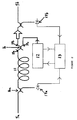
- the structure of a typical optical amplifier unit is illustrated in Figure 2 .
- the input fibre (5a) of the fibre transmission line (5) carries the input signal, which first enters a fibre optic coupler (14a).
- the signal is split into two unequal parts (typically in a ratio of 1:20), the smaller part of the coupler output being branched off to a monitor diode (17a).
- the main output of the coupler (14a) passes through into an erbium doped fibre amplifier (EDFA) (11).
- EDFA erbium doped fibre amplifier
- the amplified output from the EDFA (11) passes into a first input (19a) of a multiplexer (16), which is adapted such that substantially the entire signal at the carrier wavelength passes out through a first output (19b).
- the carrier wavelength are selected to lie close to 1560 nm.
- An EDFA provides amplification for light at 1560 nm when it is pumped with light at 1480 nm.
- the pump light is provided by an appropriate pump laser (12), which may be, for example, an InGaAsP laser.
- Pumping light is provided through second port (19c) of the multiplexer (16), the multiplexer being adapted such that substantially all the pumping light is transmitted to the EDFA through first input (19a) (serving as an output in this direction).
- the multiplexer (16) is adapted such that at the carrier wavelengths, substantially all the light is transmitted directly from first multiplexer input (19a) to the first output (19b) with no transfer across the coupler to the second port (19c), whereas at the pumping wavelength, there is a substantially complete transfer of pumping light across the coupler from second port (19c) to the first input (19a). It is possible through alternative structures to pump the EDFA at the input, or in the middle, rather than at the output side. It is possible to pump, for example, at both input and output sides - this can be advantageous in the case of failure in one pumping connection.
- an isolator (15) is required in the output path of the carrier wavelength signal to prevent instability and interference, which could otherwise result from reflections at the output port of the repeater.
- the isolator (15) has very low attenuation in the forward direction (typically ⁇ 1dB) and very high attenuation in the reverse direction (typically > 25dB).
- the output from the isolator (15) is provided as input to a further coupler (14b), from which the greater part of the signal is transmitted back out onto the transmission fibre (5) at output (5b), a small part of the signal being split off to a further monitor diode (17b).
- Monitor diodes (17a), (17b) hence enable monitoring of the input and output power levels of the EDFA.
- the input power level monitor (17a) monitors the light received from the previous amplifier via the cable. Any fault in the cable or in the previous amplifier will change the input power. As the previous amplifier has had its output power level monitored (by a monitor diode (17b)), the fault can be located to the previous repeater or to the cable in between.
- Either monitor diode may also be used as a means of receiving supervisory signals for the supervisory section (13): advantageously, the input monitor diode (17a) is used for this purpose, as if the repeater itself is faulty the output monitor diode (17b) may not be able to detect the supervisory signals.
- Separate photodiodes are provided so that the power of the pump laser (12) can be monitored at the supervisory section (13).
- the repeater units can be subjected to external control: for example, to adjust the gain of the amplifiers in order to optimise a given signal or correct an imbalance.
- signals indicative of the status of the repeater it is also necessary for signals indicative of the status of the repeater to be fed back and/or forward to an external control point.
- This is also desirable in the event of a physical break or other fault in the cable: the position of the break or fault in terms of the repeaters on the cable can be determined by use of such feedback.
- responses signals are sent back to the terminal that initiated the response. This can be achieved, for example, with a Figure 2 repeater by modulation of the pump laser power by supervisory section (13). This will result in modulation of the output power of the traffic signals output by the EDFA, this modulation being detectable at a receiving station.
- Provision of information from the repeater to the external control point is generally achieved by a passive loop-back system.
- An exemplary arrangement is described in Hirst et al, Electronics Letters 29 (3): 255-6, 1993 .
- an optical coupler is provided at the output side of the amplifier, and a small part of the entire signal amplified is split off. The split-off signal is then looped back by means of a further optical coupler on to the fibre carrying signals along the trunk in the other direction.
- each coupler will provide about 10dB of loss for this loop-back path, with the result that approximately 1 % of the signal amplified is looped back.
- the transmitted test signal is thus received back at the external control station on another fibre (and much attenuated) for processing.
- Such looped test signals can be discriminated from noise.
- By comparison of looped signals from different repeaters with each other it is possible to deduce which repeater has an especially low or high gain, or to determine in which section of cable there is a cable break.
- the present invention is directed to the different problem of provision of supervisory information to the individual repeaters from the point of external control.
- Various options for solution are discussed in Hadjifotiou, A., Brannan, J., Hirst, I.J., "Supervisory Options for Optical Amplifier Systems", Fourth IEE Conference on Telecommunications Systems in Manchester, England, IEE Conference publication 371, 18th to 21st April 1993, pp 53 to 56 .
- Several of the options there considered were found to have significant disadvantages.
- One option proposed was to transmit supervisory signals along the electrical power feed to the fibre optic cable: this, however, offers only a low bandwidth for communication and in long systems may lead to a need for high voltage components in order to satisfy power feed requirements.
- An alternative option is to use a stand alone system with a wholly separate channel to that used for data transmission, for example a 1300 nm channel, used for its operation.
- a stand alone system with a wholly separate channel to that used for data transmission, for example a 1300 nm channel, used for its operation.
- Such an arrangement offers a very high capacity, but requires the use of substantial additional hardware. This is because the 1300 nm signal will not be amplified by the amplifiers for the traffic signals and thus will not be regenerated without a separate regeneration network: a 1300 nm laser or LED and a suitable optical receiver are thus required at each repeater.
- a preferred option is to employ modulation of the optical carriers used for transmitting data signals.
- the arrangement shown in Figure 2 is in fact adapted for this form of supervisory control.
- the principle of operation is that low frequency, low intensity supervisory information is modulated onto the optical data signal sent out from the terminal providing the external control. This is detected at the repeater by a low frequency receiver: in the Figure 2 case, the low frequency receiver for extracting supervisory information is a photodiode (17a).
- a photodiode is a semiconductor device adapted to produce an output current proportional to the power of the light incident upon it.
- a silicon diode is an advantageous choice of photodiode for use in this arrangement.
- the invention provides a method of providing supervisory signals to amplifiers of a fibre optic system, said fibre optic system carrying traffic signals at one or more traffic signal carrier wavelengths from a first terminal station of the fibre optic system, wherein the traffic signals are amplified by said amplifiers so that the traffic signals are maintained in strength along said fibre optic cable system for detection at a second terminal station, characterised in that a carrier wavelength different from the one or more carrier wavelengths used for the traffic signals is employed to carry a supervisory signal but no traffic signals and wherein the fibre optic system is adapted such that the supervisory signal is amplified such that the supervisory signal is maintained in strength along the fibre optic system by the same said amplifiers amplifying the traffic signals, and wherein supervisory information is provided on its carrier wavelength by modulation at a frequency substantially lower than that of a traffic bit rate for detection by detectors located at said amplifiers.
- the supervisory information is provided by modulation at substantially 200% of the supervisory signal.
- either the supervisory signal carrier wavelength is variable, or two or more fixed supervisory signal carrier wavelengths are provided.
- a supervisory signal carrier wavelengths is spaced from the traffic signal carrier wavelengths in such a manner that the supervisory signal can be removed by optical filtering at the second terminal station.
- the invention further provides a fibre optic system comprising:
- the detectors are photodiodes, especially silicon diodes.
- the means for providing the supervisory carrier signal comprises a tunable laser source.
- FIG. 1 shows an example of a fibre-optic transmission system. This transmission system is used here in a comparison of methods of provision of a supervisory signal for amplifiers in a fibre optic system.
- Supervisory signals are provided at terminal station (1) for each of the 200 amplifiers along the transmission fibre (5) between the two terminal stations, send station (1) and receiving station (2).
- Eight carrier wavelengths (6) are used, four of which are dropped and replaced by a signal at the same wavelength, each at one of four add/drop multiplexers (4), which are spaced forty amplifiers apart along the transmission fibre (5). Any modulation on a signal which is dropped at an add/drop multiplexer (4) will be lost from the transmission fibre (5).
- the response at the monitor diode used to detect the supervisory signal at each amplifier where there are a plurality of carrier wavelengths incident is given by the analysis that follows.
- I R ⁇ e 1 + e 2 + e 3 + ... e n 2
- I R ( e 1 2 + e 2 2 + e 3 2 + ... e n 2 + 2 ⁇ e 1 ⁇ e 2 + 2 ⁇ e 1 ⁇ e 3 + 2 ⁇ e 1 ⁇ e 4 ... )
- I R ( E 1 2 / 2 + E 2 2 / 2 + E 3 2 / 2 + ... E n 2 / 2 ) + R ⁇ E 1 ⁇ E 2 2 ⁇ cos ( ( ⁇ 1 - ⁇ 2 ) t + ⁇ 1 - ⁇ 2 ) + E 1 ⁇ E 3 2 ⁇ cos ( ( ⁇ 1 - ⁇ 3 ) t + ⁇ 1 - ⁇ 3 ) + ...
- the first set of terms is the current due to the total optical power of the incident wavelengths.
- the second set of terms is the ac current due to the difference frequencies.
- ⁇ 1 and ⁇ 2 are traffic optical signal frequencies, one or both of which are modulated with supervisory information.
- a wavelength difference of 1nm is a frequency difference of 123Ghz.
- Typical spacings between traffic wavelengths are 98Ghz(0.8nm).
- the slow speed repeater monitor diode will not respond to these frequencies and therefore only first set of terms can give an output.
- the traffic wavelengths are modulated with NRZ (non return to zero) data and only their low frequency components are detected.
- the traffic wavelengths carrying random data signals (bit rate 2.5Gbit/s) produce a noise-like signal at low frequency. This noise sets the SNR of the supervisory signal.
- the signal power is very much greater than the ASE noise. This is true for amplifiers at the start of the system, but there will be an effect towards the end of the line, where the ASE noise power dilutes the modulation.
- Such dilution can be offset by increasing the level of the supervisory channel or channels relative to the data channels towards the end of the system (e.g. by moving the supervisory wavelength(s) closer to the centre wavelength, where there is less attenuation).
- the electrical SNR at a detector is given by the following equation.
- the ASE noise has been neglected.
- the modulating waveform is assumed to be a square wave.
- Set A comprised the four wavelengths dropped to minor stations (3) (Wavelengths 1, 2, 7, 8).
- Set B comprised the four wavelengths not dropped to minor stations (Wavelengths 3,4,5,6).
- Set C comprised four shortest wavelengths, two of which were dropped to minor station (3) (Wavelengths 1, 2, 3,4).
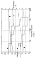
- Figure 6 illustrates use of a single carrier wavelength to provide the supervisory signal to the amplifier (or to a predetermined subset of the amplifiers).
- Four of the wavelengths are considered, Wavelengths 3, 4, 7 and 8.
- the disposition of wavelengths with regard to the transmission fibre response is such that each of the wavelengths shown has a pair with essentially the same response (e.g. Wavelengths 1 and 8).
- Wavelength 8 provides the best response for the first 100 amplifiers and Wavelength 4 provides the best response for the last 100 amplifiers.
- the minimum modulation occurs at 100 amplifiers, and is 0.6% whatever wavelength is used.
- Wavelengths 1. 2, 7 and 8 would probably be adjusted down in level, as these wavelengths do not traverse the whole transmission fibre (5). If this were to happen where a wavelength is employed as the modulation carrier, modulation would have to be increased further to compensate for any reduction in level.
- a single, separate carrier wavelength, not used to carry a traffic signal, is employed for transmission of supervisory information.
- This carrier wavelength is preferably chosen to fall within the envelope of wavelengths formed by the carrier Wavelengths 1 to 8, but is a wavelength sufficiently different from any of these such that the SNR of the traffic data will not be significantly reduced (see below).
- This supervisory wavelength is chosen so that the supervisory signal will be amplified satisfactorily by the repeater amplifiers, but also so that the data can be extracted from the total transmitted at the receive terminal (2) ( and the minor stations (3)) without penalty.
- modulation index and supervisory SNR are given by the following expressions:
- the modulation index can be calculated at a point in the line from the following equation.
- Comparison Method 1 Comparison Method 2 Comparison Method 3
- Comparison Method 1 Description All Wavelengths Modulated Four Wavelengths Modulated One Wavelength Modulated Dedicated Wavelength Terminal Modulation percentage for 5 % at each amplifier 8.3 % 12. 5 % 41.6% 5 % Minimum SNR at an amplifier 33.4dB 34dB 34.4dB 32dB Terminal penalty (eye closure) Moderate on all channels Large on modulated channels Very large on modulated channels None directly
- Method 1 in accordance with the present invention, is particularly advantageous.
- a particularly significant issue is that of the terminal penalty.
- Digital signals received at a terminal can be represented by superposition of consecutive unit waveforms as an "eye pattern", the "opening" of the eye defining a boundary in which no signal can exist under any condition of code pattern in the transmitted signal. Any decision level for determining a logical 1 or 0 in the signal should thus lie within the eye opening. Noise in a given signal channel acts to close the eye opening of the relevant eye pattern, and thus serves to reduce the possibility of receipt of a signal on that channel without error.
- optical filtering separates the optical traffic signals into individual wavelengths.
- a high speed diode recovers the NRZ from the optical signal and a low pass band delimiting filter with a cut at approximately half the bit rate is used to shape the spectrum.
- the difference frequency terms between the frequencies employed will be rejected by the band limiting filter, but the power variations of the supervisory wavelength caused by on/off modulation are detected.
- the modulation frequency is much lower than the bit rate, use of appropriate filters and decisions circuitry can reduce the effects of modulation, but even these methods cannot altogether eliminate the effect.
- the supervisory carrier wavelength is most desirable for the supervisory carrier wavelength to be "agile": that is to say, that the carrier wavelength can be changed and, in effect, tuned to a particular set of repeaters.
- the supervisory carrier wavelength could be provided, for example, by a tunable laser source adapted to cycle between two such values.
- Tuning of laser sources can be achieved by variation of drive current (to achieve small changes), by variation of an external cavity length, by temperature (to effect relatively large 2-3 nm changes) or by use of additional electrodes.
- One example of a tunable laser source is the Hewlett-Packard HP 1868A.
- a still higher degree of uniformity in response could be achieved by use of more than two choices of supervisory carrier wavelength to achieve a finer division of the repeaters into supervisory groups.
- An effective practical alternative to the use of a wavelength agile supervisory carrier is to employ two (or more) fixed supervisory carrier wavelengths, each with a fixed send level, for transmitting supervisory signals - the equipment to enable this approach will generally be lower in cost.
- supervisory carrier wavelengths would be at ⁇ 0.96 nm and ⁇ 0.82nm from the band centre.
- An advantage of using fixed supervisory carrier wavelengths is that the wavelengths used can be chosen to lie close to half way between traffic carrier wavelengths, thus rendering them particularly easy to remove at a receive terminal by optical filtering.
- Positioning a supervisory wavelength exactly half way between adjacent traffic wavelengths of an evenly-spaced set of traffic wavelengths may be disadvantageous.
- the supervisory signal may be affected by product signals (e.g., if A and B are the adjacent traffic wavelengths, and C is the supervisory wavelength, then the product A+B-C has the same wavelength as the supervisory C - however other products will lie intermediate between other traffic wavelengths).
- a slight offset from the halfway point avoids contamination of either the supervisory signal or the traffic signals with such products.
- a modification that may be advantageous where there are amplifiers to be monitored in a branch after an add/drop multiplexer is to tune the supervisory carrier wavelengths very close (inside the optical filter bandwidth) to the branched traffic carrier wavelength: this would make supervision of these amplifiers possible with only a very small penalty to other traffic channels.
- a drawback of the use of dedicated wavelengths for supervisory activity is that a portion of amplifier output power is required by the additional signal or signals. This means that there is a reduction in level of the traffic signals, with a consequent increase in the ASE noise. For 5% modulation the noise is found to be of the order of 0.1dB, which is very much less than the modulated channel penalty at a receiver. The relationship of the degree of modulation to the ASE noise penalty is shown in Figure 8 .
- 5% modulation provides in practice sufficient SNR for error free communication from the send terminal to the repeater amplifiers (SNR being here calculated with a noise bandwidth of 4 kHz).
- SNR being here calculated with a noise bandwidth of 4 kHz.
- the supervisory system can be used both for regular routine checks and also for fault detection and location. Routine checks may include a weekly monitoring of each repeater in the system for its parameters (input and output levels, pump powers and currents). Occasionally an adjustable parameter (such as pump power) may be altered to compensate for ageing.
- supervisory signals are sent out by one terminal station (or more than one terminal station, according to convenience and the configuration of the network) at a supervisory wavelength selected for a given repeater, detected by the relevant photodiode in the repeater and interpreted and acted upon by the supervisory section of the repeater. Where output from the supervisory section to the terminal station is required (for example, in returning parameter values), this may be by modulation of the pump laser power as previously described with reference to the prior art.
- Such a routine scan would, generally, be such as to address each repeater in turn starting from one end of the network. This is advantageous as it will lead to the minimum number of supervisory wavelength changes (either in tuning the agile source, or in selecting between given ones of fixed supervisory wavelengths) in systems where there are groups of repeaters such that each repeater in a given group is assigned the same supervisory wavelength, as the scan would then also cover the supervisory groups in sequence.
- the number of repeaters in a group is determined to provide the best balance between optimisation for each individual repeater (for which, ideally, a different supervisory wavelength would be employed for each repeater) and convenience of use and simplicity of design (which would reduce the number of supervisory wavelengths).
- fault location could be achieved by interrogating a repeater in the centre of the system (or in the centre of the region where the fault is already known to be) and observing whether a signal is returned from the supervisory section of that repeater. This process can be adopted iteratively until the faulty repeater is located. The same procedure can be followed in the case of an intermittent fault - monitoring is carried out sufficiently long for each repeater to determine whether the fault is present or absent in the part of the system sampled. As before, there is for each repeater a wavelength selected for providing supervisory signals.
Landscapes
- Physics & Mathematics (AREA)
- Electromagnetism (AREA)
- Engineering & Computer Science (AREA)
- Computer Networks & Wireless Communication (AREA)
- Signal Processing (AREA)
- Optical Communication System (AREA)
Abstract
Claims (12)
- Procédé de fourniture de signaux de supervision à des amplificateurs d'un système à fibre optique, ledit système à fibre optique transportant des signaux de trafic à une ou plusieurs longueurs d'onde de porteuse de signal de trafic depuis une première station terminale du système à fibre optique, dans lequel les signaux de trafic sont amplifiés par lesdits amplificateurs de sorte que les signaux de trafic gardent leur intensité le long dudit système de câble à fibre optique pour être détectés au niveau d'une seconde station terminale, caractérisé en ce qu'une longueur d'onde de porteuse différente de la ou des longueurs d'onde de porteuse utilisée(s) pour les signaux de trafic est employée pour transporter un signal de supervision mais aucun signal de trafic et dans lequel le système à fibre optique est adapté pour que le signal de supervision soit amplifié de sorte que le signal de supervision garde son intensité le long du système à fibre optique par les mêmes dits amplificateurs qui amplifient les signaux de trafic, et dans lequel l'information de supervision est fournie sur sa longueur d'onde de porteuse par modulation à une fréquence sensiblement inférieure à celle d'un débit binaire de trafic pour être détectée par des détecteurs situés au niveau desdits amplificateurs.
- Procédé selon la revendication 1, dans lequel deux ou plusieurs longueurs d'onde de porteuse de signal de supervision sont prévues, chacune employée à transporter un signal de supervision mais aucun signal de trafic,
et dans lequel l'information de supervision est offerte par modulation de chacune desdites deux ou plusieurs longueurs d'onde de porteuse avec un signal de supervision. - Procédé selon la revendication 1 ou 2, dans lequel la ou chaque longueur d'onde de porteuse pour un signal de supervision est une longueur d'onde fixe.
- Procédé selon la revendication 1 ou 2, dans lequel la ou chaque longueur d'onde de porteuse pour un signal de supervision est variable en longueur d'onde afin de pouvoir optimiser la réponse sur un amplificateur ou un groupe d'amplificateurs donné.
- Procédé selon l'une quelconque des revendications précédentes, dans lequel l'information de supervision est offerte par modulation à sensiblement 200 % des signaux de supervision.
- Procédé selon l'une quelconque des revendications précédentes, dans lequel la ou les longueurs d'onde de porteuse de signal de supervision est/sont adaptée(s) pour être enlevées des longueurs d'onde de porteuse de signal de trafic par filtrage optique.
- Procédé selon la revendication 5 ou 6, dans lequel la ou les longueurs d'onde de porteuse de signal de supervision est/sont sensiblement intermédiaire(s) entre des longueurs d'onde de porteuse de signal de trafic adjacentes.
- Procédé selon l'une quelconque des revendications précédentes, dans lequel la ou les longueurs d'onde de porteuse de signal de supervision est/sont positionnées par rapport aux longueurs d'onde de porteuse de signal de trafic ou sensiblement de façon à éliminer les interférences avec le signal de supervision ou les signaux de trafic provenant de produits des signaux de supervision et de trafic.
- Système à fibre optique comprenant :une première station terminale (1) ;une seconde station terminale (2) connectée à la première station terminale par un câble à fibre optique (5) ;des moyens de fourniture de signaux de trafic (1, 2, 7, 8) à une ou plusieurs longueurs d'onde de porteuse de signal de trafic à ladite première station terminale (1) ; dans lequel ledit câble à fibre optique (5) comprend une pluralité d'amplificateurs (11), caractérisé par des moyens de fourniture audit premier terminal (1) d'un signal de supervision (3, 4, 5, 6) à des longueurs d'onde de porteuse ne portant pas de trafic différentes de ladite ou desdites longueurs d'onde de porteuse de signal et de modulation de cette porteuse avec un signal de supervision, les amplificateurs de ladite pluralité d'amplificateurs étant adaptés pour garder l'intensité le long du système à fibre optique à la fois des signaux de trafic (1, 2, 7, 8) et du signal de supervision, et dans lequel lesdits amplificateurs (11) possèdent des détecteurs associés (17a, 17b) adaptés pour détecter une information de supervision fournie par modulation du signal de supervision à une fréquence significativement inférieure à celle d'un débit binaire de signal de trafic.
- Système à fibre optique selon la revendication 9, dans lequel lesdits moyens de fourniture du signal de supervision comprennent une source laser réglable.
- Système à fibre optique selon la revendication 9, dans lequel lesdits moyens de fourniture du signal de supervision sont adaptés pour le fournir à deux longueurs d'onde de porteuse de signal de supervision ou plus.
- Système à fibre optique selon l'une quelconque des revendications 9 à 11, comprenant en outre un ou plusieurs multiplexeurs d'insertion/extraction (4) entre la première station terminale (1) et la seconde station terminale (2) afin d'extraire des signaux de trafic et/ou de recevoir des signaux de trafic en provenance de branches (3) du système à fibre optique.
Applications Claiming Priority (3)
| Application Number | Priority Date | Filing Date | Title |
|---|---|---|---|
| GB9612156 | 1996-06-11 | ||
| GB9612156A GB2314224A (en) | 1996-06-11 | 1996-06-11 | Fibre optic transmission |
| PCT/GB1997/001485 WO1997048193A1 (fr) | 1996-06-11 | 1997-06-02 | Transmission par fibre optique avec amplificateurs a fibre et signaux de controle |
Publications (2)
| Publication Number | Publication Date |
|---|---|
| EP0904641A1 EP0904641A1 (fr) | 1999-03-31 |
| EP0904641B1 true EP0904641B1 (fr) | 2008-08-06 |
Family
ID=10795079
Family Applications (1)
| Application Number | Title | Priority Date | Filing Date |
|---|---|---|---|
| EP97924151A Expired - Lifetime EP0904641B1 (fr) | 1996-06-11 | 1997-06-02 | Transmission par fibre optique avec amplificateurs a fibre et signaux de controle |
Country Status (6)
| Country | Link |
|---|---|
| US (1) | US6639701B1 (fr) |
| EP (1) | EP0904641B1 (fr) |
| JP (1) | JP4005139B2 (fr) |
| DE (1) | DE69738885D1 (fr) |
| GB (1) | GB2314224A (fr) |
| WO (1) | WO1997048193A1 (fr) |
Families Citing this family (14)
| Publication number | Priority date | Publication date | Assignee | Title |
|---|---|---|---|---|
| US6452701B1 (en) * | 1997-03-19 | 2002-09-17 | Fujitsu Limited | Wavelength division multiplexing communications network supervisory system |
| JP3532759B2 (ja) * | 1998-03-11 | 2004-05-31 | 富士通株式会社 | Wdm通信システムにおける中継装置及び同装置の送信レベル制御方法 |
| GB2347807B (en) * | 1999-03-12 | 2001-02-28 | Marconi Comm Ltd | Signal transmission system |
| DE10024238B4 (de) * | 2000-05-12 | 2006-11-23 | Fraunhofer-Gesellschaft zur Förderung der angewandten Forschung e.V. | Verfahren zur Qualitäts-und Identitätskontrolle von Wellenlängenkanälen in optischen Übertragungsnetzen |
| JP3391341B2 (ja) | 2000-08-23 | 2003-03-31 | 日本電気株式会社 | 光伝送路監視システム及びその監視装置及びその監視方法 |
| JP3813063B2 (ja) * | 2001-02-01 | 2006-08-23 | 富士通株式会社 | 通信システム及び波長分割多重装置 |
| AU2002226395A1 (en) | 2001-12-27 | 2003-09-04 | Pirelli Submarine Telecom Systems Italia S.P.A. | Optical transmission system with raman amplifiers comprising a supervisory system |
| US7254326B2 (en) | 2001-12-27 | 2007-08-07 | Alcatel | Optical transmission system with raman amplifiers comprising a supervisory system |
| JP4516868B2 (ja) * | 2005-03-22 | 2010-08-04 | 富士通株式会社 | 光増幅多段中継伝送路における障害点評定方法、装置及びシステム |
| US8682159B2 (en) * | 2008-07-09 | 2014-03-25 | Tyco Electronics Subsea Communications Llc | Optical communication system supporting detection and communication networks |
| US8340515B2 (en) * | 2009-11-03 | 2012-12-25 | Fujitsu Limited | Method and system for monitoring optical dispersion in an optical signal |
| FI20115072A0 (fi) | 2011-01-25 | 2011-01-25 | Pulse Finland Oy | Moniresonanssiantenni, -antennimoduuli ja radiolaite |
| US20140029105A1 (en) * | 2012-07-25 | 2014-01-30 | John Edward Fay | Solar igloo |
| CN103503337B (zh) | 2013-01-15 | 2016-01-20 | 华为海洋网络有限公司 | 一种通信设备及方法 |
Family Cites Families (10)
| Publication number | Priority date | Publication date | Assignee | Title |
|---|---|---|---|---|
| JPH0828680B2 (ja) * | 1987-07-23 | 1996-03-21 | 国際電信電話株式会社 | 双方向光ファイバ通信系の障害点監視方式 |
| GB2245121B (en) * | 1990-06-16 | 1994-03-16 | Stc Plc | Telemetry |
| DE4109683A1 (de) * | 1991-03-23 | 1992-09-24 | Standard Elektrik Lorenz Ag | System fuer optische signaluebertragung, insbesondere optisches kabelfernsehsystem, mit ueberwachungs- und dienstkanaleinrichtung |
| JP3110805B2 (ja) * | 1991-07-01 | 2000-11-20 | 富士通株式会社 | 光中継システム |
| US5555477A (en) * | 1992-04-08 | 1996-09-10 | Hitachi, Ltd. | Optical transmission system constructing method and system |
| US5383046A (en) | 1992-05-29 | 1995-01-17 | Fujitsu Limited | Supervisory and control signal transmitting system for use in optically amplifying repeaters system |
| FR2696302A1 (fr) | 1992-09-28 | 1994-04-01 | Cit Alcatel | Liaison à fibres optiques et amplificateur pour cette liaison. |
| US5436750A (en) * | 1993-05-07 | 1995-07-25 | Nec Corporation | Optical repeatered transmission with fault locating capability |
| CA2155693C (fr) | 1994-08-25 | 1999-12-14 | Daniel A. Fishman | Methode et dispositif de controle de systemes de transmission optique et de localisation de defaillance |
| JPH10224306A (ja) * | 1997-01-31 | 1998-08-21 | Fujitsu Ltd | 光伝送システム |
-
1996
- 1996-06-11 GB GB9612156A patent/GB2314224A/en not_active Withdrawn
-
1997
- 1997-06-02 WO PCT/GB1997/001485 patent/WO1997048193A1/fr not_active Ceased
- 1997-06-02 US US09/202,250 patent/US6639701B1/en not_active Expired - Lifetime
- 1997-06-02 EP EP97924151A patent/EP0904641B1/fr not_active Expired - Lifetime
- 1997-06-02 DE DE69738885T patent/DE69738885D1/de not_active Expired - Lifetime
- 1997-06-02 JP JP50133698A patent/JP4005139B2/ja not_active Expired - Fee Related
Also Published As
| Publication number | Publication date |
|---|---|
| GB2314224A (en) | 1997-12-17 |
| JP4005139B2 (ja) | 2007-11-07 |
| JP2000512452A (ja) | 2000-09-19 |
| WO1997048193A1 (fr) | 1997-12-18 |
| EP0904641A1 (fr) | 1999-03-31 |
| US6639701B1 (en) | 2003-10-28 |
| GB9612156D0 (en) | 1996-08-14 |
| DE69738885D1 (de) | 2008-09-18 |
Similar Documents
| Publication | Publication Date | Title |
|---|---|---|
| EP0703678B1 (fr) | Surveillance de performance et localisation de défauts dans des systèmes de transmission optique | |
| CA2215115C (fr) | Systeme et methode de limitation de la saturation croisee dans les reseaux a amplification optique | |
| US6128111A (en) | Monitoring of nonlinear effects | |
| EP0762677B1 (fr) | Système de communication, optique déterminant le spectre d'un signal multiplexé par longueur d'onde et exécutant diverses opérations en fonction du spectre déterminé | |
| US6639701B1 (en) | Fiber optic transmission with fiber amplifiers and supervisory signals | |
| EP0896444B1 (fr) | Télésurveillance d'un système de transmission optique utilisant des signaux de surveillance de ligne | |
| JP3670583B2 (ja) | 波長分割多重システムにおいて信号損失を検出するための方法およびシステム | |
| US7151875B2 (en) | Method and apparatus for balancing the power of optical channels traversing an optical add drop multiplexer | |
| US5485299A (en) | Communications system | |
| JPH0895097A (ja) | 波長多重光増幅器 | |
| US6404522B1 (en) | Optical communication method and system using wavelength division multiplexing | |
| US6599039B1 (en) | Optical transmission monitoring apparatus, optical transmission monitoring method, optical amplification system, method of controlling optical amplification system, and optical transmission system | |
| US6748179B2 (en) | WDM channel monitoring system and method | |
| EP0525058A1 (fr) | Signalisation de defauts dans une liaison de communication optique. | |
| US5557265A (en) | Method and system for indicating an optical transmit amplifier fault | |
| US6469814B1 (en) | Apparatus and method for detecting channel information from WDM optical signal by using wavelength selective photo detector | |
| JP3536974B2 (ja) | 光受信器の入力信号異常検出システム及び方法 | |
| EP0717513B1 (fr) | Méthode et système pour indiquer un défaut dans un amplificateur optique de transmission | |
| JPH0993223A (ja) | 光通信装置及び波長検出方法 | |
| MXPA97006857A (es) | Sistema y metodo para mitigar saturacion cruzada en redes amplificadas opticamente |
Legal Events
| Date | Code | Title | Description |
|---|---|---|---|
| PUAI | Public reference made under article 153(3) epc to a published international application that has entered the european phase |
Free format text: ORIGINAL CODE: 0009012 |
|
| 17P | Request for examination filed |
Effective date: 19981222 |
|
| AK | Designated contracting states |
Kind code of ref document: A1 Designated state(s): DE FR GB IT |
|
| RAP1 | Party data changed (applicant data changed or rights of an application transferred) |
Owner name: ALCATEL LUCENT |
|
| GRAP | Despatch of communication of intention to grant a patent |
Free format text: ORIGINAL CODE: EPIDOSNIGR1 |
|
| GRAS | Grant fee paid |
Free format text: ORIGINAL CODE: EPIDOSNIGR3 |
|
| GRAA | (expected) grant |
Free format text: ORIGINAL CODE: 0009210 |
|
| AK | Designated contracting states |
Kind code of ref document: B1 Designated state(s): DE FR GB IT |
|
| REG | Reference to a national code |
Ref country code: GB Ref legal event code: FG4D |
|
| REF | Corresponds to: |
Ref document number: 69738885 Country of ref document: DE Date of ref document: 20080918 Kind code of ref document: P |
|
| PLBE | No opposition filed within time limit |
Free format text: ORIGINAL CODE: 0009261 |
|
| STAA | Information on the status of an ep patent application or granted ep patent |
Free format text: STATUS: NO OPPOSITION FILED WITHIN TIME LIMIT |
|
| 26N | No opposition filed |
Effective date: 20090507 |
|
| PG25 | Lapsed in a contracting state [announced via postgrant information from national office to epo] |
Ref country code: IT Free format text: LAPSE BECAUSE OF FAILURE TO SUBMIT A TRANSLATION OF THE DESCRIPTION OR TO PAY THE FEE WITHIN THE PRESCRIBED TIME-LIMIT Effective date: 20080806 |
|
| REG | Reference to a national code |
Ref country code: FR Ref legal event code: GC Effective date: 20131018 |
|
| REG | Reference to a national code |
Ref country code: FR Ref legal event code: RG Effective date: 20141016 |
|
| REG | Reference to a national code |
Ref country code: FR Ref legal event code: PLFP Year of fee payment: 19 |
|
| REG | Reference to a national code |
Ref country code: FR Ref legal event code: CA Effective date: 20150521 |
|
| REG | Reference to a national code |
Ref country code: FR Ref legal event code: CA Effective date: 20150521 |
|
| PGFP | Annual fee paid to national office [announced via postgrant information from national office to epo] |
Ref country code: GB Payment date: 20150618 Year of fee payment: 19 Ref country code: DE Payment date: 20150619 Year of fee payment: 19 |
|
| PGFP | Annual fee paid to national office [announced via postgrant information from national office to epo] |
Ref country code: FR Payment date: 20150619 Year of fee payment: 19 |
|
| REG | Reference to a national code |
Ref country code: DE Ref legal event code: R119 Ref document number: 69738885 Country of ref document: DE |
|
| GBPC | Gb: european patent ceased through non-payment of renewal fee |
Effective date: 20160602 |
|
| REG | Reference to a national code |
Ref country code: FR Ref legal event code: ST Effective date: 20170228 |
|
| PG25 | Lapsed in a contracting state [announced via postgrant information from national office to epo] |
Ref country code: DE Free format text: LAPSE BECAUSE OF NON-PAYMENT OF DUE FEES Effective date: 20170103 Ref country code: FR Free format text: LAPSE BECAUSE OF NON-PAYMENT OF DUE FEES Effective date: 20160630 |
|
| PG25 | Lapsed in a contracting state [announced via postgrant information from national office to epo] |
Ref country code: GB Free format text: LAPSE BECAUSE OF NON-PAYMENT OF DUE FEES Effective date: 20160602 |