EP0904504B1 - Verbindungselement für profilbehaftete riemenenden - Google Patents
Verbindungselement für profilbehaftete riemenenden Download PDFInfo
- Publication number
- EP0904504B1 EP0904504B1 EP98919139A EP98919139A EP0904504B1 EP 0904504 B1 EP0904504 B1 EP 0904504B1 EP 98919139 A EP98919139 A EP 98919139A EP 98919139 A EP98919139 A EP 98919139A EP 0904504 B1 EP0904504 B1 EP 0904504B1
- Authority
- EP
- European Patent Office
- Prior art keywords
- connecting element
- parts
- belt end
- belt
- pins
- Prior art date
- Legal status (The legal status is an assumption and is not a legal conclusion. Google has not performed a legal analysis and makes no representation as to the accuracy of the status listed.)
- Expired - Lifetime
Links
- 238000000926 separation method Methods 0.000 description 5
- 238000004519 manufacturing process Methods 0.000 description 3
- 230000037431 insertion Effects 0.000 description 2
- 238000003780 insertion Methods 0.000 description 2
- 239000012790 adhesive layer Substances 0.000 description 1
- 238000005452 bending Methods 0.000 description 1
- 238000010276 construction Methods 0.000 description 1
- 238000006073 displacement reaction Methods 0.000 description 1
- 239000000463 material Substances 0.000 description 1
- 230000003534 oscillatory effect Effects 0.000 description 1
Images

Classifications
-
- F—MECHANICAL ENGINEERING; LIGHTING; HEATING; WEAPONS; BLASTING
- F16—ENGINEERING ELEMENTS AND UNITS; GENERAL MEASURES FOR PRODUCING AND MAINTAINING EFFECTIVE FUNCTIONING OF MACHINES OR INSTALLATIONS; THERMAL INSULATION IN GENERAL
- F16G—BELTS, CABLES, OR ROPES, PREDOMINANTLY USED FOR DRIVING PURPOSES; CHAINS; FITTINGS PREDOMINANTLY USED THEREFOR
- F16G3/00—Belt fastenings, e.g. for conveyor belts
-
- E—FIXED CONSTRUCTIONS
- E05—LOCKS; KEYS; WINDOW OR DOOR FITTINGS; SAFES
- E05F—DEVICES FOR MOVING WINGS INTO OPEN OR CLOSED POSITION; CHECKS FOR WINGS; WING FITTINGS NOT OTHERWISE PROVIDED FOR, CONCERNED WITH THE FUNCTIONING OF THE WING
- E05F15/00—Power-operated mechanisms for wings
- E05F15/60—Power-operated mechanisms for wings using electrical actuators
- E05F15/603—Power-operated mechanisms for wings using electrical actuators using rotary electromotors
- E05F15/665—Power-operated mechanisms for wings using electrical actuators using rotary electromotors for vertically-sliding wings
- E05F15/668—Power-operated mechanisms for wings using electrical actuators using rotary electromotors for vertically-sliding wings for overhead wings
- E05F15/681—Power-operated mechanisms for wings using electrical actuators using rotary electromotors for vertically-sliding wings for overhead wings operated by flexible elongated pulling elements, e.g. belts
-
- E—FIXED CONSTRUCTIONS
- E05—LOCKS; KEYS; WINDOW OR DOOR FITTINGS; SAFES
- E05F—DEVICES FOR MOVING WINGS INTO OPEN OR CLOSED POSITION; CHECKS FOR WINGS; WING FITTINGS NOT OTHERWISE PROVIDED FOR, CONCERNED WITH THE FUNCTIONING OF THE WING
- E05F15/00—Power-operated mechanisms for wings
- E05F15/60—Power-operated mechanisms for wings using electrical actuators
- E05F15/603—Power-operated mechanisms for wings using electrical actuators using rotary electromotors
- E05F15/632—Power-operated mechanisms for wings using electrical actuators using rotary electromotors for horizontally-sliding wings
- E05F15/643—Power-operated mechanisms for wings using electrical actuators using rotary electromotors for horizontally-sliding wings operated by flexible elongated pulling elements, e.g. belts, chains or cables
-
- E—FIXED CONSTRUCTIONS
- E05—LOCKS; KEYS; WINDOW OR DOOR FITTINGS; SAFES
- E05Y—INDEXING SCHEME ASSOCIATED WITH SUBCLASSES E05D AND E05F, RELATING TO CONSTRUCTION ELEMENTS, ELECTRIC CONTROL, POWER SUPPLY, POWER SIGNAL OR TRANSMISSION, USER INTERFACES, MOUNTING OR COUPLING, DETAILS, ACCESSORIES, AUXILIARY OPERATIONS NOT OTHERWISE PROVIDED FOR, APPLICATION THEREOF
- E05Y2900/00—Application of doors, windows, wings or fittings thereof
- E05Y2900/10—Application of doors, windows, wings or fittings thereof for buildings or parts thereof
- E05Y2900/106—Application of doors, windows, wings or fittings thereof for buildings or parts thereof for garages
Definitions
- the invention relates to a connecting element for receiving profiled Belt ends.
- belts with profile are preferred Timing belt, used.
- the use of such belts points towards chain drives the advantage of a lower noise level.
- finite belts are usually used, which easily adjust to the desired one Dimension can be reduced.
- Such a connecting element is known from DE-GM 87 17 016.
- the disclosed connector comprises two opposite, with a negative Image of the profiled belt end with engaging elements in the the belt ends are inserted one in the direction of movement of the belt to create a positive connection.
- This connection is against separation or secured by moving that on each of the engaging elements a sleeve is pushed on with the end of the belt.
- the sleeve has such dimensions Inner walls on that a pressing force on the belt end and engaging element is exerted when the sleeve is pushed on, which means not only a separation both parts to be connected but also a loosening of the sleeve can be prevented should.
- DE-GM 89 05 227 a connecting device is disclosed in which the loosening of a pushed sleeve should be prevented by the Sleeve has a projection which in an annular groove of the connecting element intervenes.
- the object of the present invention is, starting from DE-U-8 717 016, a connecting element for those with profile To create belt ends that ensure a secure connection and is easy to manufacture and assemble.
- the parts may have pins and pin holes. It is for each pin on one of the parts an associated pin hole on one to be connected Part provided, whereby an exact assembly of the parts is possible.
- the outer diameter the pins and the inner diameter of the pin holes are designed such that frictional forces both when assembling the parts and when loosening the parts must be overcome. These frictional forces exceed stresses caused by vibrations or temperature fluctuations during operation, thereby loosening the parts from each other and thus loosening the Belt end is prevented from the connecting element.
- connection of the pins with the pin holes can be secured by material connection his.
- a connection can e.g. be made by that on the Pins before applying an adhesive layer is applied.
- the parts of the connecting element for receiving a screw aligned with each other Have holes.
- the inside diameter of the holes can be larger be as the outside diameter of the screws, so that the screws through a Mother must be secured. If the diameter of the hole is below that Outside diameter of the screw, screws are used to form the connection used that cut a thread when screwing in and thus a firm connection create.
- the holes can accommodate appropriate screws also be provided with a pre-cut thread.
- connection of the parts of the connecting element by screws causes the parts are detachable, but are firmly connected to each other, causing a shift or loosening of the belt end in the joining direction is prevented.
- the parts have flexible projections and recesses, the flexible Projections of one part in corresponding recesses of the other to be connected Intervene. This is before the parts are screwed together achieved a stable connection.
- the areas with a corresponding negative profile are designed in such a way that they match the profile of the belt end precisely, whereby a frictional connection is achieved in the joining direction. This causes on the one hand, a holder of the belt end in the parts of the connecting element during assembly and secondly an additional safeguard against that Shift the belt end in the joining direction.
- the connecting element can have a recess or groove for receiving of a driver.
- a driver for gate operators mounted on a sled that moves according to the movement of the belt moved and by a mechanical connection with a door leaf Opening and closing causes.
- the connecting element has a cylindrical shape in the assembled state and the Outside diameter of the cylinder is only slightly above the width of the recorded Belt lies.
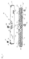
- the connecting element 10 shown in Fig. 1 comprises the two parts 30 and 30 ', which are connected to one another after insertion of one or more belt ends become.
- the belt or the belt ends are not shown in the drawing.
- the part 30 ' has areas 20 which have a negative image of the profile of the belt end include.
- the belt end is received in the area 20 in such a way that only moving or removing the belt end from the part 30 ' in the joining direction is possible.
- the profile of the belt end Regions 20 a plane and a profiled side opposite this.
- the teeth of the belt engage in the profiled side, creating a positive fit Connection in the direction of movement of the belt is created.
- Form locking in all directions deviating from the joining direction is furthermore thereby achieved that the inserted belt end on the opposite of the profiling lying side is limited by the flat side of the area 20.
- part 30 After inserting the end of the belt, part 30 is placed on part 30 '.
- the Part 30 may also have a negative image of the profile of the belt ends Include areas not shown in the drawing, around the part 30 'projecting edge of the belt end. Will the belt end however, taken up by the part 30 ′ in its entire width, the part 30 has no profiled area and in this case serves as a cover.
- the attacks 70 serve as lateral limitation and guidance and thus grant one correct insertion of the belt end.
- the parts 30 and 30 ' are assembled using pins 40 and Pin holes 42, both parts 30 and 30 'corresponding pins 40 respectively and have pin holes 42.
- the pins 40 and pin holes 42 serve as a guide when assembling the parts 30 and 30 'and can also with appropriate precise fitting of the inside and outside diameter of the pins 40 and the pin holes 42 ensure a positive connection.
- the parts 30 and 30 ' are in operation particularly against separation secured that screws 52 through bores 50, which are through both parts 30th and 30 'extend and align, are insertable.
- the part 30 ' is thereby Screw head held in the bore 50 by means of a phase during the fixation of part 30 via a thread cut when screw 52 is screwed in he follows.
- projections 60 and recesses 62 are provided, as in particular emerges from Fig. 2.
- the projections 60 and recesses 62 extend on the outer circumference of parts 30 and 30 ', both parts corresponding to each other Have projections and recesses.
- the protrusions 60 are flexibly executed and snap on a recessed edge on its front End at a corresponding edge of the recess 62.
- the projections 62 form with the outside 12 the connecting element 10 a smooth and thus easy to handle surface.
- a projection 60 can be released on the one hand by the projection 60 is raised from the outside over the edge of the recess 62.
- the projection 60 is raised from the outside over the edge of the recess 62.
- connection by means of pins 40, screws 52 and projections 62 can be released the belt can be removed from the connecting element and extended by a longer one or shorter version can be replaced.
- the connecting element 10 After inserting the belt end into parts 30 and 30 ', the connecting element 10 has a cylindrical shape, the outer diameter of the Cylinder only slightly exceeds the width of the belt. This Arrangement has particular advantages if only one for the belt very limited space is available, which is the use of a large volume or projecting edges and projections connecting element excludes.
Landscapes
- Engineering & Computer Science (AREA)
- General Engineering & Computer Science (AREA)
- Mechanical Engineering (AREA)
- Belt Conveyors (AREA)
- Clamps And Clips (AREA)
- Devices For Conveying Motion By Means Of Endless Flexible Members (AREA)
- Hooks, Suction Cups, And Attachment By Adhesive Means (AREA)
- Automotive Seat Belt Assembly (AREA)
- Non-Disconnectible Joints And Screw-Threaded Joints (AREA)
Applications Claiming Priority (3)
| Application Number | Priority Date | Filing Date | Title |
|---|---|---|---|
| DE29705941U | 1997-04-03 | ||
| DE29705941U DE29705941U1 (de) | 1997-04-03 | 1997-04-03 | Verbindungselement für profilbehaftete Riemenenden |
| PCT/EP1998/001725 WO1998045618A1 (de) | 1997-04-03 | 1998-03-24 | Verbindungselement für profilbehaftete riemenenden |
Publications (2)
| Publication Number | Publication Date |
|---|---|
| EP0904504A1 EP0904504A1 (de) | 1999-03-31 |
| EP0904504B1 true EP0904504B1 (de) | 2003-05-28 |
Family
ID=8038414
Family Applications (1)
| Application Number | Title | Priority Date | Filing Date |
|---|---|---|---|
| EP98919139A Expired - Lifetime EP0904504B1 (de) | 1997-04-03 | 1998-03-24 | Verbindungselement für profilbehaftete riemenenden |
Country Status (11)
| Country | Link |
|---|---|
| US (1) | US6309318B1 (es) |
| EP (1) | EP0904504B1 (es) |
| JP (1) | JP2000511625A (es) |
| CN (1) | CN1100950C (es) |
| AT (1) | ATE241767T1 (es) |
| BR (1) | BR9804813A (es) |
| DE (2) | DE29705941U1 (es) |
| ES (1) | ES2200337T3 (es) |
| PT (1) | PT904504E (es) |
| WO (1) | WO1998045618A1 (es) |
| ZA (1) | ZA982811B (es) |
Families Citing this family (7)
| Publication number | Priority date | Publication date | Assignee | Title |
|---|---|---|---|---|
| DE29705941U1 (de) * | 1997-04-03 | 1997-07-10 | Marantec Antriebs- Und Steuerungstechnik Gmbh & Co. Produktions Kg, 33428 Marienfeld | Verbindungselement für profilbehaftete Riemenenden |
| US6896430B2 (en) * | 2002-10-23 | 2005-05-24 | Hewlett-Packard Development Company, L.P. | Compliant belt attach |
| DE102005038446B4 (de) | 2005-08-03 | 2008-05-29 | SSI Schäfer PEEM GmbH | Verbindungseinheit für lose Zugmittelenden |
| WO2009049379A1 (en) * | 2007-10-19 | 2009-04-23 | Automatic Technology (Australia) Pty Ltd | Improvements relating to drive assemblies |
| US20090156325A1 (en) * | 2007-11-07 | 2009-06-18 | Spiralock Corporation | Attachment system for detachably securing a component to a shaft-like member |
| US9562384B2 (en) | 2011-05-24 | 2017-02-07 | Overhead Door Corporation | Wireless adapter for barrier operator systems |
| CN107701657A (zh) * | 2017-11-08 | 2018-02-16 | 无锡弗斯门控科技有限公司 | 一种同步带连接组合 |
Family Cites Families (14)
| Publication number | Priority date | Publication date | Assignee | Title |
|---|---|---|---|---|
| US2430328A (en) * | 1945-01-31 | 1947-11-04 | Daniels Frederick Arthur | V-belt |
| US3605201A (en) * | 1968-03-25 | 1971-09-20 | L M & L Corp | Endless belt assembly with improved insert coupling |
| US3924301A (en) * | 1974-07-15 | 1975-12-09 | Crane Co H W | Control actuator for gear belts and the like |
| US4049357A (en) | 1976-04-30 | 1977-09-20 | Monarch Marking Systems, Inc. | Sliding coupling device for a lanyard or the like |
| US4705495A (en) * | 1984-09-20 | 1987-11-10 | Madion Herbert E | Emergency v-belt |
| US4642081A (en) * | 1985-06-07 | 1987-02-10 | Balomenos Robert J | Adjustable drive belt |
| CH673259A5 (es) * | 1987-07-24 | 1990-02-28 | Milz Produkte Ag | |
| DE8717016U1 (de) | 1987-12-24 | 1988-03-31 | Bernal Torantriebe GmbH, 7417 Pfullingen | Elektrischer Torantrieb |
| DE8905227U1 (de) | 1989-04-25 | 1989-06-29 | Berner, Kurt, 7407 Rottenburg | Zahnriemenschloß für zahnriemenbetätigte Torantriebe |
| US5057058A (en) * | 1990-09-10 | 1991-10-15 | Crudup Jack M | Split pulley |
| SE469951B (sv) | 1992-02-28 | 1993-10-11 | Icl Data Ab | Fäste för kuggremmar |
| US5391121A (en) * | 1994-01-05 | 1995-02-21 | Schramm; Michael R. | Method and apparatus for tool-less drive-belt installation |
| DE19534932A1 (de) * | 1995-09-20 | 1997-03-27 | Marantec Antrieb Steuerung | Verbindungsvorrichtung für profilbehaftete Antriebsmittel |
| DE29705941U1 (de) | 1997-04-03 | 1997-07-10 | Marantec Antriebs- Und Steuerungstechnik Gmbh & Co. Produktions Kg, 33428 Marienfeld | Verbindungselement für profilbehaftete Riemenenden |
-
1997
- 1997-04-03 DE DE29705941U patent/DE29705941U1/de not_active Expired - Lifetime
-
1998
- 1998-03-24 EP EP98919139A patent/EP0904504B1/de not_active Expired - Lifetime
- 1998-03-24 CN CN98800735A patent/CN1100950C/zh not_active Expired - Fee Related
- 1998-03-24 AT AT98919139T patent/ATE241767T1/de not_active IP Right Cessation
- 1998-03-24 DE DE59808514T patent/DE59808514D1/de not_active Expired - Fee Related
- 1998-03-24 PT PT98919139T patent/PT904504E/pt unknown
- 1998-03-24 BR BR9804813A patent/BR9804813A/pt active Search and Examination
- 1998-03-24 WO PCT/EP1998/001725 patent/WO1998045618A1/de not_active Ceased
- 1998-03-24 ES ES98919139T patent/ES2200337T3/es not_active Expired - Lifetime
- 1998-03-24 JP JP10542309A patent/JP2000511625A/ja active Pending
- 1998-03-24 US US09/194,821 patent/US6309318B1/en not_active Expired - Fee Related
- 1998-04-02 ZA ZA982811A patent/ZA982811B/xx unknown
Also Published As
| Publication number | Publication date |
|---|---|
| PT904504E (pt) | 2003-10-31 |
| DE59808514D1 (de) | 2003-07-03 |
| WO1998045618A1 (de) | 1998-10-15 |
| BR9804813A (pt) | 1999-08-17 |
| ATE241767T1 (de) | 2003-06-15 |
| ES2200337T3 (es) | 2004-03-01 |
| CN1249021A (zh) | 2000-03-29 |
| EP0904504A1 (de) | 1999-03-31 |
| JP2000511625A (ja) | 2000-09-05 |
| CN1100950C (zh) | 2003-02-05 |
| DE29705941U1 (de) | 1997-07-10 |
| ZA982811B (en) | 1998-10-05 |
| US6309318B1 (en) | 2001-10-30 |
Similar Documents
| Publication | Publication Date | Title |
|---|---|---|
| DE19622069B4 (de) | Gehäuse und Beschlag zur Ausbildung einer Verbindung | |
| EP0904504B1 (de) | Verbindungselement für profilbehaftete riemenenden | |
| EP0411239A1 (de) | Steckerträger zum Anbau an ein Aggregatgehäuse | |
| EP1394347B1 (de) | Vorrichtung zur Führung von verschiebbaren Trennelementen und elastisches Führungselement | |
| EP3535824B1 (de) | Sammelschienenhalter und eine entsprechende anordnung | |
| DE60012848T2 (de) | Türgriff für Kraftfahrzeug | |
| DE1914116A1 (de) | Durch Zusammenstecken und Einrasten montierbares Kameragehaeuse | |
| EP1666688B1 (de) | Band für Fenster, Türen und dergleichen | |
| DE3151224C2 (de) | Vorrichtung zur Befestigung eines Getriebes an einem Rahmen von Fenstern, Türen oder dergleichen | |
| DE20302370U1 (de) | Duschabtrennung | |
| EP0709052A1 (de) | Profil | |
| DE3151668C2 (es) | ||
| DE4416004C1 (de) | Gehäuse, insbesondere zur Aufnahme elektrischer oder elektronischer Bauteile | |
| EP3138982B1 (de) | Bandteil eines bandes | |
| DE4237368A1 (de) | Behälter für Tonträger | |
| EP4286635B1 (de) | Gleitschiene für einen türantrieb | |
| EP1638381A1 (de) | Gehäuse und Gehäuseanordnung | |
| DE102023123023A1 (de) | Türantrieb für eine Fahrzeugtür | |
| EP0903063A1 (de) | Gehäuse | |
| DE102007044057A1 (de) | Vorrichtung für die zeitweilige Anbringung einer Schiebetür an einer Kraftfahrzeugkarosserie während mindestens eines Abschnitts des Fertigungsprozesses | |
| DE202018104023U1 (de) | Abstandshalter zur Einstellung eines Sollabstandes zwischen zwei Komponenten | |
| DE102024200866A1 (de) | Griffbaugruppe für ein Kraftfahrzeug und Verfahren zum Montieren eines Türgriffs | |
| DE102021117099A1 (de) | Montageeinrichtung für eine Verbindungseinrichtung, Verbindungseinrichtung sowie Verfahren zum Sichern einer Verbindungseinrichtung | |
| EP1351115A2 (de) | Anordnung zur Festlegung eines Slotwinkels | |
| DE102023124315A1 (de) | Verbindungsbeschlag, Möbel und Verfahren zur Montage |
Legal Events
| Date | Code | Title | Description |
|---|---|---|---|
| PUAI | Public reference made under article 153(3) epc to a published international application that has entered the european phase |
Free format text: ORIGINAL CODE: 0009012 |
|
| 17P | Request for examination filed |
Effective date: 19981203 |
|
| AK | Designated contracting states |
Kind code of ref document: A1 Designated state(s): AT BE CH DE DK ES FR GB GR IE IT LI NL PT SE |
|
| 17Q | First examination report despatched |
Effective date: 20020301 |
|
| GRAH | Despatch of communication of intention to grant a patent |
Free format text: ORIGINAL CODE: EPIDOS IGRA |
|
| GRAH | Despatch of communication of intention to grant a patent |
Free format text: ORIGINAL CODE: EPIDOS IGRA |
|
| RAP1 | Party data changed (applicant data changed or rights of an application transferred) |
Owner name: MARANTEC ANTRIEBS- UND STEUERUNGSTECHNIK GMBH & |
|
| GRAA | (expected) grant |
Free format text: ORIGINAL CODE: 0009210 |
|
| AK | Designated contracting states |
Designated state(s): AT BE CH DE DK ES FR GB GR IE IT LI NL PT SE |
|
| REG | Reference to a national code |
Ref country code: GB Ref legal event code: FG4D Free format text: NOT ENGLISH |
|
| REG | Reference to a national code |
Ref country code: CH Ref legal event code: EP |
|
| REG | Reference to a national code |
Ref country code: IE Ref legal event code: FG4D Free format text: GERMAN |
|
| REG | Reference to a national code |
Ref country code: CH Ref legal event code: NV Representative=s name: BOVARD AG PATENTANWAELTE |
|
| REF | Corresponds to: |
Ref document number: 59808514 Country of ref document: DE Date of ref document: 20030703 Kind code of ref document: P |
|
| RIN2 | Information on inventor provided after grant (corrected) |
Inventor name: HOERMANN, MICHAEL |
|
| PG25 | Lapsed in a contracting state [announced via postgrant information from national office to epo] |
Ref country code: SE Free format text: LAPSE BECAUSE OF FAILURE TO SUBMIT A TRANSLATION OF THE DESCRIPTION OR TO PAY THE FEE WITHIN THE PRESCRIBED TIME-LIMIT Effective date: 20030828 Ref country code: GR Free format text: LAPSE BECAUSE OF FAILURE TO SUBMIT A TRANSLATION OF THE DESCRIPTION OR TO PAY THE FEE WITHIN THE PRESCRIBED TIME-LIMIT Effective date: 20030828 Ref country code: DK Free format text: LAPSE BECAUSE OF FAILURE TO SUBMIT A TRANSLATION OF THE DESCRIPTION OR TO PAY THE FEE WITHIN THE PRESCRIBED TIME-LIMIT Effective date: 20030828 |
|
| GBT | Gb: translation of ep patent filed (gb section 77(6)(a)/1977) | ||
| REG | Reference to a national code |
Ref country code: ES Ref legal event code: FG2A Ref document number: 2200337 Country of ref document: ES Kind code of ref document: T3 |
|
| PG25 | Lapsed in a contracting state [announced via postgrant information from national office to epo] |
Ref country code: IE Free format text: LAPSE BECAUSE OF NON-PAYMENT OF DUE FEES Effective date: 20040324 |
|
| PG25 | Lapsed in a contracting state [announced via postgrant information from national office to epo] |
Ref country code: ES Free format text: LAPSE BECAUSE OF NON-PAYMENT OF DUE FEES Effective date: 20040325 |
|
| ET | Fr: translation filed | ||
| PLBE | No opposition filed within time limit |
Free format text: ORIGINAL CODE: 0009261 |
|
| STAA | Information on the status of an ep patent application or granted ep patent |
Free format text: STATUS: NO OPPOSITION FILED WITHIN TIME LIMIT |
|
| 26N | No opposition filed |
Effective date: 20040302 |
|
| PG25 | Lapsed in a contracting state [announced via postgrant information from national office to epo] |
Ref country code: PT Free format text: LAPSE BECAUSE OF NON-PAYMENT OF DUE FEES Effective date: 20041015 |
|
| REG | Reference to a national code |
Ref country code: PT Ref legal event code: MM4A Free format text: LAPSE DUE TO NON-PAYMENT OF FEES Effective date: 20040930 |
|
| REG | Reference to a national code |
Ref country code: IE Ref legal event code: MM4A |
|
| PGFP | Annual fee paid to national office [announced via postgrant information from national office to epo] |
Ref country code: BE Payment date: 20050318 Year of fee payment: 8 Ref country code: AT Payment date: 20050318 Year of fee payment: 8 |
|
| PGFP | Annual fee paid to national office [announced via postgrant information from national office to epo] |
Ref country code: CH Payment date: 20050321 Year of fee payment: 8 |
|
| PGFP | Annual fee paid to national office [announced via postgrant information from national office to epo] |
Ref country code: NL Payment date: 20050322 Year of fee payment: 8 |
|
| PG25 | Lapsed in a contracting state [announced via postgrant information from national office to epo] |
Ref country code: IT Free format text: LAPSE BECAUSE OF NON-PAYMENT OF DUE FEES;WARNING: LAPSES OF ITALIAN PATENTS WITH EFFECTIVE DATE BEFORE 2007 MAY HAVE OCCURRED AT ANY TIME BEFORE 2007. THE CORRECT EFFECTIVE DATE MAY BE DIFFERENT FROM THE ONE RECORDED. Effective date: 20050324 |
|
| REG | Reference to a national code |
Ref country code: ES Ref legal event code: FD2A Effective date: 20040325 |
|
| PG25 | Lapsed in a contracting state [announced via postgrant information from national office to epo] |
Ref country code: AT Free format text: LAPSE BECAUSE OF NON-PAYMENT OF DUE FEES Effective date: 20060324 |
|
| PG25 | Lapsed in a contracting state [announced via postgrant information from national office to epo] |
Ref country code: LI Free format text: LAPSE BECAUSE OF NON-PAYMENT OF DUE FEES Effective date: 20060331 Ref country code: CH Free format text: LAPSE BECAUSE OF NON-PAYMENT OF DUE FEES Effective date: 20060331 Ref country code: BE Free format text: LAPSE BECAUSE OF NON-PAYMENT OF DUE FEES Effective date: 20060331 |
|
| PG25 | Lapsed in a contracting state [announced via postgrant information from national office to epo] |
Ref country code: NL Free format text: LAPSE BECAUSE OF NON-PAYMENT OF DUE FEES Effective date: 20061001 |
|
| REG | Reference to a national code |
Ref country code: CH Ref legal event code: PL |
|
| NLV4 | Nl: lapsed or anulled due to non-payment of the annual fee |
Effective date: 20061001 |
|
| BERE | Be: lapsed |
Owner name: *MARANTEC ANTRIEBS- UND STEUERUNGSTECHNIK G.M.B.H. Effective date: 20060331 |
|
| PGFP | Annual fee paid to national office [announced via postgrant information from national office to epo] |
Ref country code: GB Payment date: 20080326 Year of fee payment: 11 |
|
| PGFP | Annual fee paid to national office [announced via postgrant information from national office to epo] |
Ref country code: DE Payment date: 20080328 Year of fee payment: 11 |
|
| PGFP | Annual fee paid to national office [announced via postgrant information from national office to epo] |
Ref country code: FR Payment date: 20080319 Year of fee payment: 11 |
|
| GBPC | Gb: european patent ceased through non-payment of renewal fee |
Effective date: 20090324 |
|
| REG | Reference to a national code |
Ref country code: FR Ref legal event code: ST Effective date: 20091130 |
|
| PG25 | Lapsed in a contracting state [announced via postgrant information from national office to epo] |
Ref country code: DE Free format text: LAPSE BECAUSE OF NON-PAYMENT OF DUE FEES Effective date: 20091001 |
|
| PG25 | Lapsed in a contracting state [announced via postgrant information from national office to epo] |
Ref country code: GB Free format text: LAPSE BECAUSE OF NON-PAYMENT OF DUE FEES Effective date: 20090324 Ref country code: FR Free format text: LAPSE BECAUSE OF NON-PAYMENT OF DUE FEES Effective date: 20091123 |