EP0904481B1 - Carottier - Google Patents
Carottier Download PDFInfo
- Publication number
- EP0904481B1 EP0904481B1 EP97925061A EP97925061A EP0904481B1 EP 0904481 B1 EP0904481 B1 EP 0904481B1 EP 97925061 A EP97925061 A EP 97925061A EP 97925061 A EP97925061 A EP 97925061A EP 0904481 B1 EP0904481 B1 EP 0904481B1
- Authority
- EP
- European Patent Office
- Prior art keywords
- core
- free end
- end portion
- end element
- inner barrel
- Prior art date
- Legal status (The legal status is an assumption and is not a legal conclusion. Google has not performed a legal analysis and makes no representation as to the accuracy of the status listed.)
- Expired - Lifetime
Links
Images

Classifications
-
- E—FIXED CONSTRUCTIONS
- E21—EARTH OR ROCK DRILLING; MINING
- E21B—EARTH OR ROCK DRILLING; OBTAINING OIL, GAS, WATER, SOLUBLE OR MELTABLE MATERIALS OR A SLURRY OF MINERALS FROM WELLS
- E21B25/00—Apparatus for obtaining or removing undisturbed cores, e.g. core barrels or core extractors
-
- E—FIXED CONSTRUCTIONS
- E21—EARTH OR ROCK DRILLING; MINING
- E21B—EARTH OR ROCK DRILLING; OBTAINING OIL, GAS, WATER, SOLUBLE OR MELTABLE MATERIALS OR A SLURRY OF MINERALS FROM WELLS
- E21B21/00—Methods or apparatus for flushing boreholes, e.g. by use of exhaust air from motor
- E21B21/10—Valve arrangements in drilling-fluid circulation systems
Definitions
- the free end element of the inner tube has a circular lip parallel to the longitudinal axis of rotation and located in an annular housing, of the crown, which also extends parallel to the axis longitudinal rotation.
- the inner tube may be of a different material (for example of fiberglass coated with a binder) of that of the outer tube which is usually made of steel, the differential expansions that these two tubes undergo object to obtaining and / or maintaining a desired adjustment of the fluid passage.
- a carrot entering the inner tube can grow this somewhat towards the top of the outer tube, in function of a clearance in the thrust ball or bearings with balls which connect the inner and outer tubes, and this can significantly change the above setting.
- a bad adjusting said passage can lead for example to a too much core fluid flow to the core and to a possible deep alteration of it by washing, etc., or lead for example to contact too large between said surface of revolution of the free end member and the inner surface of the crown or outer tube, resulting in a seizure of these surfaces during the rotation of one relative to each other, or a deformation and / or rupture free end member, etc.
- the object of the present invention is to remedy to the aforementioned drawbacks, and to others not explained above but known to those skilled in the art, and provide a means to obtain in a way safe and simple the right setting, even setting up a zero or near zero passage for the fluid of coring between the free end element of the tube interior and the corresponding internal bearing surface, without annoying pressure from one on the other, so without them aforesaid risks of seizure, deformation or rupture at this location.
- the free end element is mounted in the core barrel so that it can slide coaxially over a section end of the inner tube, between a position in which the surface of revolution is in contact with the internal surface of the crown or of the tube respectively outside and an extreme position away from this internal surface.
- the sliding free end element and the end section each have a cooperating stop with each other, when the inner tube is removed from its core position in the outer tube, so as to block the free end element on the end section in another position extreme located beyond said contact position in starting from the extreme position away from the surface internal.
- Figure 1 shows schematically in axial section of a section of a corer equipped with the following the invention.
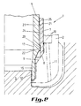
- Figure 2 shows schematically, at another scale, in axial half-section a section of another corer equipped according to the invention.
- the core barrel 1 of FIG. 1 presents a coring ring 2 mounted on an outer tube 3, intended inter alia for the rotational drive of the crown 2, and an inner tube 4 intended to receive a core 5 during a coring operation.
- a split tapered ring 6 is provided in the tube interior 4 and is intended to block therein a carrot.
- the inner 4 and outer 3 tubes are each formed of various sections of tubes attached one to the other for example by screwing and are practically coaxial.
- the inner tube 4 has one end anterior free 7, considering the direction of travel of core sampler 1 during a core drilling operation.
- This element free end 7 is delimited by a surface of revolution 8 arranged to cooperate with a surface internal 9 of the crown 2, or if necessary of the tube exterior 3 according to the reciprocal arrangement of these two components mounted one on top of or the other, so that adjust between the surface of revolution 8 and the surface internal 9 a determined passage of coring fluid.
- the fluid of coring is brought into an annular conduit 10, delimited by the inner 4 and outer 3 tubes, way to get to the bottom of a core hole by via nozzles there from crown 2. It can be desired that a small amount of coring fluid can however pass directly from the conduit annular 10 to a gap 12 between a carrot 5 and the crown 2, so as to lubricate and cool this place of friction between these two components. The fluid flow to this gap must however be limited to prevent this fluid from damaging the carrot produced.
- the free end element 7 is mounted in the core barrel 1 so that it can slide coaxially on an end section 13 of the inner tube 4, between a position in which the surface of revolution 8 is in contact with said internal surface 9 and a extreme position away from this internal surface 9.
- the free end element 7 ends in a groove 14 which extends parallel to the longitudinal axis of the core barrel 1 and which has in its bottom the surface internal 9 for supporting the surface of revolution 8.
- the free end element 7 abuts against a surface internal 9 of the crown 2 and the end section 13 has another free end member 15 therein fixed and which in the coring position in the corer 1, can protrude from the end member free 7 sliding.
- the sliding mounting can be adjusted to that the pressure of the coring fluid, acting on the surfaces of the free end element 7, press one against each other the surface of revolution 8 and the surface internal 9.
- the pressing force can be considered as low given the small surface area or can present the free end element 7 at the fluid pressure.
- This pressing force can however be increased by known hydraulic means (pressure losses for example and / or increase in flow) to prevent the free end member 7 either pushed upwards, for example by debris from carrot passing between the crown 2 and the section end 13.
- the contact between the surfaces of revolution 8 and internal 9 can be continuous and the passage of fluid from the duct annular 10 towards the gap 12 is then practically closed.
- Sliding free end element 7 can also be mounted so that it can be rotated the end section 13. This allows for example to distribute the wear due to friction during rotation of the outer tube 3 relative to the inner tube 4, between the contact point of the surfaces of revolution 8 and internal 9 and the contact point of the element free end 7 and end section 13, or well to report this wear to this last place which for example the components are removable and replaceable.
- At least said section end 13 can be removably arranged on the rest of the inner tube 4.
- Free end elements 7 and section end 13 can be made of materials different from those of the inner 4, outer 3 and crown 2 and be adapted according to the friction at undergo.
- the free end member 7 and the end section 13 each have a stop 20, 21 cooperating with each other, when the inner tube 4 is removed from its coring position in the outer tube 3.
- the stops 20, 21 cooperate so as to block the free end element 7 on said end section 13 in another extreme position (not shown) located opposite said position of contact between surfaces of revolution 8 and internal 9 compared to the first extreme position mentioned, disposed away from the inner surface 9.
- the end section 13 may include as a stop 20, on the bottom side well in the coring position, a collar external cylindrical 22 and, between this and the rest of the inner tube 4, a cylindrical body 23 of diameter external lower than the external cylindrical collar 22.
- the free end element 7 then comprises, side of the same well bottom, a cylindrical hole 24 opening whose internal diameter is adapted to the outer diameter of the outer collar 22 for sliding above and, on the opposite side to the bottom of the well, in as a stop 21, an internal cylindrical collar 25 of which the internal diameter is less than that of the hole cylindrical 24 and is adapted to the external diameter of the cylindrical body 23 for said sliding.
- the removable arrangement of the end section 13 on the rest of the inner tube 4 can be constituted by example by an external screw thread assembly on the end section 13, at its end away from the well bottom, and with internal thread on the end corresponding to the rest of the inner tube 4.
- the external screw pitch has a diameter at most equal to the external diameter of the cylindrical body 23 and, when the threads are cylindrical, they are advantageously threads on the left.
- a seal 30 can be mounted by example in the inner surface of the cylindrical collar internal 25 in order to cooperate with the peripheral surface of the cylindrical body 23 and thus improve a tightness to the coring fluid at this location.
- the core barrel 1 of the invention comprises advantageously a tapered split ring 6, such as shown in Figure 1 and having a groove in V 33 where it is split, a cylindrical surface internal 34 roughened, in known manner, for hang a carrot 1 and a frustoconical surface external 35 grooved.
- One or more notches 40 may be provided on one face of the free end element 7 turned towards the rest of the inner tube 3. These notches 40 can be used to take off, possibly by pressure of fluid, an element 7 relative to said remaining inner tube 3.
- Notches 41 may be provided on the end face of the unscrewable end section 13, to receive a tool for screwing or unscrewing of this section 13.
Landscapes
- Engineering & Computer Science (AREA)
- Geology (AREA)
- Life Sciences & Earth Sciences (AREA)
- Mining & Mineral Resources (AREA)
- Environmental & Geological Engineering (AREA)
- Fluid Mechanics (AREA)
- Physics & Mathematics (AREA)
- General Life Sciences & Earth Sciences (AREA)
- Geochemistry & Mineralogy (AREA)
- Mechanical Engineering (AREA)
- Earth Drilling (AREA)
- Investigation Of Foundation Soil And Reinforcement Of Foundation Soil By Compacting Or Drainage (AREA)
- Joints Allowing Movement (AREA)
- Sampling And Sample Adjustment (AREA)
Applications Claiming Priority (3)
| Application Number | Priority Date | Filing Date | Title |
|---|---|---|---|
| BE9600504A BE1010325A3 (fr) | 1996-06-05 | 1996-06-05 | Carottier. |
| BE9600504 | 1996-06-05 | ||
| PCT/EP1997/002964 WO1997046790A1 (fr) | 1996-06-05 | 1997-06-03 | Carottier |
Publications (2)
| Publication Number | Publication Date |
|---|---|
| EP0904481A1 EP0904481A1 (fr) | 1999-03-31 |
| EP0904481B1 true EP0904481B1 (fr) | 2002-01-16 |
Family
ID=3889782
Family Applications (1)
| Application Number | Title | Priority Date | Filing Date |
|---|---|---|---|
| EP97925061A Expired - Lifetime EP0904481B1 (fr) | 1996-06-05 | 1997-06-03 | Carottier |
Country Status (7)
| Country | Link |
|---|---|
| US (1) | US6145604A (no) |
| EP (1) | EP0904481B1 (no) |
| BE (1) | BE1010325A3 (no) |
| CA (1) | CA2257377C (no) |
| DE (1) | DE69709638T2 (no) |
| NO (1) | NO315530B1 (no) |
| WO (1) | WO1997046790A1 (no) |
Families Citing this family (11)
| Publication number | Priority date | Publication date | Assignee | Title |
|---|---|---|---|---|
| BE1011502A3 (fr) | 1997-10-17 | 1999-10-05 | Dresser Ind | Carottier. |
| US20070261886A1 (en) * | 2006-05-15 | 2007-11-15 | Baker Hughes Incorporated | Core drill assembly with adjustable total flow area and restricted flow between outer and inner barrel assemblies |
| CZ201222A3 (cs) * | 2012-01-13 | 2013-08-14 | Vysoká Skola Bánská Technická - Univerzita Ostrava | Mechanická ruka pro vyjmutí jádrových vývrtu |
| RU2516311C2 (ru) * | 2012-05-14 | 2014-05-20 | Открытое акционерное общество "Научно-производственное предприятие "Бурсервис" | Устройство для разделения и фиксации керна при разборке керноотборного снаряда |
| US20140027182A1 (en) * | 2012-07-26 | 2014-01-30 | National Oilwell Varco, L.P. | Telescoping core barrel |
| US20150337654A1 (en) * | 2013-02-05 | 2015-11-26 | Sadi Sami Ahmad ALSHANNAQ | Obtaining a downhole core sample measurement using logging while coring |
| CN103590773A (zh) * | 2013-11-16 | 2014-02-19 | 无锡中地地质装备有限公司 | 卡簧 |
| CN105508374A (zh) * | 2015-12-29 | 2016-04-20 | 苏州市诚品精密机械有限公司 | 一种新型卡簧 |
| CN105672926B (zh) * | 2016-01-19 | 2018-03-23 | 宝鸡石油机械有限责任公司 | 海底钻机用液压驱动型护帽旋扣装置 |
| US10597963B2 (en) * | 2018-04-26 | 2020-03-24 | Baker Hughes Oilfield Operations Llc | Coring tools including a core catcher |
| CN112901097B (zh) * | 2021-01-29 | 2023-06-30 | 陈建和 | 一种移动式石油勘探设备 |
Family Cites Families (7)
| Publication number | Priority date | Publication date | Assignee | Title |
|---|---|---|---|---|
| US1870592A (en) * | 1931-05-21 | 1932-08-09 | Schuerman Martin | Core drill |
| GB1160409A (en) * | 1966-09-28 | 1969-08-06 | Mindrill Ltd | Core Drills. |
| GB2000824B (en) * | 1977-07-06 | 1982-05-19 | American Coldset Corp | Method and core barrel apparatus for obtaining and retrieving subterranean formation samples |
| US4553613A (en) * | 1983-09-09 | 1985-11-19 | Norton Christensen, Inc. | Hydraulic lift inner barrel in a drill string coring tool |
| US4512423A (en) * | 1983-09-09 | 1985-04-23 | Christensen, Inc. | Coring device with an improved weighted core sleeve and anti-gripping collar |
| US4643265A (en) * | 1985-03-04 | 1987-02-17 | Norton Christensen, Inc. | Core barrel apparatus for disposing a core within a thin, flexible film casing |
| US4981183A (en) * | 1988-07-06 | 1991-01-01 | Baker Hughes Incorporated | Apparatus for taking core samples |
-
1996
- 1996-06-05 BE BE9600504A patent/BE1010325A3/fr not_active IP Right Cessation
-
1997
- 1997-06-03 CA CA002257377A patent/CA2257377C/en not_active Expired - Fee Related
- 1997-06-03 US US09/194,902 patent/US6145604A/en not_active Expired - Lifetime
- 1997-06-03 DE DE69709638T patent/DE69709638T2/de not_active Expired - Lifetime
- 1997-06-03 WO PCT/EP1997/002964 patent/WO1997046790A1/fr not_active Ceased
- 1997-06-03 EP EP97925061A patent/EP0904481B1/fr not_active Expired - Lifetime
-
1998
- 1998-12-03 NO NO19985641A patent/NO315530B1/no not_active IP Right Cessation
Also Published As
| Publication number | Publication date |
|---|---|
| NO985641D0 (no) | 1998-12-03 |
| DE69709638D1 (de) | 2002-02-21 |
| DE69709638T2 (de) | 2002-10-02 |
| BE1010325A3 (fr) | 1998-06-02 |
| CA2257377C (en) | 2002-11-19 |
| CA2257377A1 (en) | 1997-12-11 |
| WO1997046790A1 (fr) | 1997-12-11 |
| NO315530B1 (no) | 2003-09-15 |
| EP0904481A1 (fr) | 1999-03-31 |
| US6145604A (en) | 2000-11-14 |
| NO985641L (no) | 1998-12-03 |
Similar Documents
| Publication | Publication Date | Title |
|---|---|---|
| EP2809962B1 (fr) | Mâchoire de cardan, assemblage pour double cardan à rotule et procédé d'usinage | |
| EP1167078B1 (fr) | Dispositif d'accrochage d'un rayon à la jante d'une roue de bicyclette | |
| EP0904481B1 (fr) | Carottier | |
| EP1916182B1 (fr) | Jeu de direction de cycle | |
| FR2937891A3 (fr) | Mandrin porte-foret auto-serrant | |
| FR2602162A1 (fr) | Systeme de fixation d'un outil sur un organe porte-outil de machine-outil, parties constitutives | |
| EP0070766B1 (fr) | Tourillon de montage de deux pièces | |
| WO1999019598A1 (fr) | Accouplement pour dispositif a transmission de forces | |
| FR2607183A1 (fr) | Appareil de forage, notamment elargisseur, et bras de coupe pour un tel appareil | |
| FR2863188A1 (fr) | Mandrin | |
| EP0373049B1 (fr) | Dispositif de fixation à un élément de structure interne d'un véhicule automobile d'une pièce d'équipement à positionner relativement à un élément de structure externe du véhicule | |
| FR2813558A1 (fr) | Dispositif d'accrochage d'un rayon a la jante d'une roue de bicyclette | |
| EP1431597B1 (fr) | Rotule metallique et son procédé de fabrication | |
| CA1123420A (fr) | Concentric barreled corer | |
| WO2009015748A1 (fr) | Dispositif d'assemblage d'un element de structure et d'une plaque superposee | |
| EP1591714B1 (fr) | Dispositif de lubrification d'un composant dans un ensemble de pièces | |
| FR2517576A1 (no) | ||
| EP1569842B1 (fr) | Assemblage d'une fourche de bicyclette et d'un jeu de direction sur un cadre de bicyclette, et fourche pour un tel assemblage. | |
| EP1209371B1 (fr) | Articulation pour commande à billes | |
| FR2752212A1 (fr) | Essieu directeur avec pivots de fusee a roulements | |
| FR2473930A2 (fr) | Outillage pour la reparation, en particulier pour rodage d'un siege de robinet | |
| CA3222174A1 (fr) | Dispositif de guidage en rotation d'un outil de forage et procede associe | |
| EP0931948A1 (fr) | Charnière pour application en micromécanique | |
| WO2007090952A1 (fr) | Mandrin pour l ' equipement d ' une machine-outil avec outil tournante | |
| FR2921993A3 (fr) | Dispositif de verrouillage destine a empecher l'actionnement non autorise d'une broche de reglage d'un appareil de sectionnement de conduite. |
Legal Events
| Date | Code | Title | Description |
|---|---|---|---|
| PUAI | Public reference made under article 153(3) epc to a published international application that has entered the european phase |
Free format text: ORIGINAL CODE: 0009012 |
|
| 17P | Request for examination filed |
Effective date: 19981230 |
|
| AK | Designated contracting states |
Kind code of ref document: A1 Designated state(s): BE DE FR GB IT NL |
|
| GRAG | Despatch of communication of intention to grant |
Free format text: ORIGINAL CODE: EPIDOS AGRA |
|
| 17Q | First examination report despatched |
Effective date: 20010314 |
|
| GRAG | Despatch of communication of intention to grant |
Free format text: ORIGINAL CODE: EPIDOS AGRA |
|
| GRAH | Despatch of communication of intention to grant a patent |
Free format text: ORIGINAL CODE: EPIDOS IGRA |
|
| GRAH | Despatch of communication of intention to grant a patent |
Free format text: ORIGINAL CODE: EPIDOS IGRA |
|
| GRAA | (expected) grant |
Free format text: ORIGINAL CODE: 0009210 |
|
| REG | Reference to a national code |
Ref country code: GB Ref legal event code: IF02 |
|
| AK | Designated contracting states |
Kind code of ref document: B1 Designated state(s): BE DE FR GB IT NL |
|
| REF | Corresponds to: |
Ref document number: 69709638 Country of ref document: DE Date of ref document: 20020221 |
|
| GBT | Gb: translation of ep patent filed (gb section 77(6)(a)/1977) |
Effective date: 20020423 |
|
| PLBE | No opposition filed within time limit |
Free format text: ORIGINAL CODE: 0009261 |
|
| STAA | Information on the status of an ep patent application or granted ep patent |
Free format text: STATUS: NO OPPOSITION FILED WITHIN TIME LIMIT |
|
| 26N | No opposition filed | ||
| REG | Reference to a national code |
Ref country code: GB Ref legal event code: 732E |
|
| NLS | Nl: assignments of ep-patents |
Owner name: HALLIBURTON ENERGY SERVICES, INC. |
|
| REG | Reference to a national code |
Ref country code: FR Ref legal event code: TP |
|
| PGFP | Annual fee paid to national office [announced via postgrant information from national office to epo] |
Ref country code: FR Payment date: 20110603 Year of fee payment: 15 |
|
| PGFP | Annual fee paid to national office [announced via postgrant information from national office to epo] |
Ref country code: NL Payment date: 20110615 Year of fee payment: 15 |
|
| PGFP | Annual fee paid to national office [announced via postgrant information from national office to epo] |
Ref country code: IT Payment date: 20110616 Year of fee payment: 15 |
|
| PGFP | Annual fee paid to national office [announced via postgrant information from national office to epo] |
Ref country code: DE Payment date: 20110630 Year of fee payment: 15 |
|
| PGFP | Annual fee paid to national office [announced via postgrant information from national office to epo] |
Ref country code: BE Payment date: 20110705 Year of fee payment: 15 |
|
| BERE | Be: lapsed |
Owner name: *HALLIBURTON ENERGY SERVICES INC. Effective date: 20120630 |
|
| REG | Reference to a national code |
Ref country code: NL Ref legal event code: V1 Effective date: 20130101 |
|
| PG25 | Lapsed in a contracting state [announced via postgrant information from national office to epo] |
Ref country code: IT Free format text: LAPSE BECAUSE OF NON-PAYMENT OF DUE FEES Effective date: 20120603 |
|
| REG | Reference to a national code |
Ref country code: FR Ref legal event code: ST Effective date: 20130228 |
|
| REG | Reference to a national code |
Ref country code: DE Ref legal event code: R119 Ref document number: 69709638 Country of ref document: DE Effective date: 20130101 |
|
| PG25 | Lapsed in a contracting state [announced via postgrant information from national office to epo] |
Ref country code: BE Free format text: LAPSE BECAUSE OF NON-PAYMENT OF DUE FEES Effective date: 20120630 Ref country code: FR Free format text: LAPSE BECAUSE OF NON-PAYMENT OF DUE FEES Effective date: 20120702 Ref country code: NL Free format text: LAPSE BECAUSE OF NON-PAYMENT OF DUE FEES Effective date: 20130101 Ref country code: DE Free format text: LAPSE BECAUSE OF NON-PAYMENT OF DUE FEES Effective date: 20130101 |
|
| PGFP | Annual fee paid to national office [announced via postgrant information from national office to epo] |
Ref country code: GB Payment date: 20140527 Year of fee payment: 18 |
|
| GBPC | Gb: european patent ceased through non-payment of renewal fee |
Effective date: 20150603 |
|
| PG25 | Lapsed in a contracting state [announced via postgrant information from national office to epo] |
Ref country code: GB Free format text: LAPSE BECAUSE OF NON-PAYMENT OF DUE FEES Effective date: 20150603 |