EP0904469B1 - Sanitary fitting in the form of a single-lever mixer tap - Google Patents
Sanitary fitting in the form of a single-lever mixer tap Download PDFInfo
- Publication number
- EP0904469B1 EP0904469B1 EP97926994A EP97926994A EP0904469B1 EP 0904469 B1 EP0904469 B1 EP 0904469B1 EP 97926994 A EP97926994 A EP 97926994A EP 97926994 A EP97926994 A EP 97926994A EP 0904469 B1 EP0904469 B1 EP 0904469B1
- Authority
- EP
- European Patent Office
- Prior art keywords
- valve
- lever
- control
- mixer
- electrically controllable
- Prior art date
- Legal status (The legal status is an assumption and is not a legal conclusion. Google has not performed a legal analysis and makes no representation as to the accuracy of the status listed.)
- Expired - Lifetime
Links
- 239000012530 fluid Substances 0.000 claims abstract description 6
- 230000000694 effects Effects 0.000 claims description 3
- 230000004913 activation Effects 0.000 claims 1
- XLYOFNOQVPJJNP-UHFFFAOYSA-N water Substances O XLYOFNOQVPJJNP-UHFFFAOYSA-N 0.000 description 18
- 230000008901 benefit Effects 0.000 description 3
- 239000007788 liquid Substances 0.000 description 3
- 238000007789 sealing Methods 0.000 description 3
- 230000006835 compression Effects 0.000 description 2
- 238000007906 compression Methods 0.000 description 2
- 230000001276 controlling effect Effects 0.000 description 2
- 230000009471 action Effects 0.000 description 1
- 230000033228 biological regulation Effects 0.000 description 1
- 230000005540 biological transmission Effects 0.000 description 1
- 239000000919 ceramic Substances 0.000 description 1
- 230000007423 decrease Effects 0.000 description 1
- 238000010586 diagram Methods 0.000 description 1
- 238000006073 displacement reaction Methods 0.000 description 1
- 239000000696 magnetic material Substances 0.000 description 1
- 230000007257 malfunction Effects 0.000 description 1
- 239000012528 membrane Substances 0.000 description 1
- 239000000203 mixture Substances 0.000 description 1
- 238000012544 monitoring process Methods 0.000 description 1
- 244000052769 pathogen Species 0.000 description 1
- 230000009467 reduction Effects 0.000 description 1
- 230000001105 regulatory effect Effects 0.000 description 1
- 230000008439 repair process Effects 0.000 description 1
- 125000006850 spacer group Chemical group 0.000 description 1
- 239000008399 tap water Substances 0.000 description 1
- 235000020679 tap water Nutrition 0.000 description 1
- 230000007306 turnover Effects 0.000 description 1
Images

Classifications
-
- E—FIXED CONSTRUCTIONS
- E03—WATER SUPPLY; SEWERAGE
- E03C—DOMESTIC PLUMBING INSTALLATIONS FOR FRESH WATER OR WASTE WATER; SINKS
- E03C1/00—Domestic plumbing installations for fresh water or waste water; Sinks
- E03C1/02—Plumbing installations for fresh water
- E03C1/05—Arrangements of devices on wash-basins, baths, sinks, or the like for remote control of taps
-
- Y—GENERAL TAGGING OF NEW TECHNOLOGICAL DEVELOPMENTS; GENERAL TAGGING OF CROSS-SECTIONAL TECHNOLOGIES SPANNING OVER SEVERAL SECTIONS OF THE IPC; TECHNICAL SUBJECTS COVERED BY FORMER USPC CROSS-REFERENCE ART COLLECTIONS [XRACs] AND DIGESTS
- Y10—TECHNICAL SUBJECTS COVERED BY FORMER USPC
- Y10T—TECHNICAL SUBJECTS COVERED BY FORMER US CLASSIFICATION
- Y10T137/00—Fluid handling
- Y10T137/8593—Systems
- Y10T137/87571—Multiple inlet with single outlet
- Y10T137/87676—With flow control
- Y10T137/87684—Valve in each inlet
- Y10T137/87692—With common valve operator
Definitions
- the invention relates to a single-lever mixer Sanitary fitting according to the features of the preamble of the claim 1.
- Sanitary fittings designed as single-lever mixers are known. They have the mixer taps that used to be common with two manually adjustable valves for cold and warm water largely replaced and usually consist of one Mixer tap with only one operating lever, which has a Control rod a control piston arranged in the mixer tap operated.
- the operating lever is on both sides can also be swiveled vertically. While through the side Swiveling the mixture of cold and warm water is carried out by the vertical pivoting movement regulating the amount of water.
- Single-lever mixer can also be operated without contact.
- a sanitary fitting designed as a single lever mixer after The preamble of claim 1 is known from US-A-5,358,213.
- this known single lever mixer however, one automatic operation to open the valve only in the closed End position of the operating lever possible because in all other manually set positions electrical opening allowing play between the actuators is canceled.
- a sanitary fitting with two is manual adjustable valves for cold and warm water known with a solenoid valve turned on in the outlet channel is. This is done using a proximity switch a control electronics operated as soon as an object enters the monitoring area of the proximity switch. Apart from the not very attractive structure of such a non-contact controlled sanitary fitting at the Parts of the solenoid valve and electrical lines are good are mounted on the spout, this valve has the disadvantage that manual switching on and off, as with conventional manually operated fittings, is no longer possible. So the power supply drops of the solenoid valve for any reason, the armature no more water can be removed.
- the invention is essentially based on the idea that Single-lever mixer tap an electrically controllable Downstream valve, its function not only by the Switching signals of the control electronics depends, but also on the position of the operating lever of the valve.
- the control rod connected to the actuating lever and the electrically controllable valve mechanically coupled that the valve on the one hand despite the corresponding opening signals generated by the proximity sensor etc. remains closed, provided that the mixer tap is closed (the operating lever of the valve is located usually in its lower position).
- the electrically controllable valve remains without a corresponding one Opening signals from the proximity sensor opened, if the mixer tap by operating the control rod is fully open (the valve lever is located usually in its upper position).
- the mechanical control of the valve depending on the Reach the position of the control rod if it is electrically controllable valve around a known solenoid valve acts.
- Such solenoid valves consist of a magnetic switching part and a mechanical valve part.
- the magnetic switching part has one for opening and existing control pin to close the valve on by an electromagnet against the pressure of a spring is axially displaceable.
- a permanent magnet provided the control pin after switching off of the electromagnet in its shifted against the pressure of the spring Holds position.
- Control rod with the permanent magnet of the magnetic switching part mechanically connected via at least one lever. Becomes the axial position of the control rod changed, so it shifts the permanent magnet also changes and changes its distance with respect to the control pin of the switching part, namely such that in the closed position of the mixer tap the permanent magnet no longer has a functionally relevant effect exerts the control pin and in the fully open Position of the control rod of the permanent magnet the control pin constantly attracts.
- the lever is designed as a lever, so that pulling the Control rod movement of the permanent magnet to the control pin towards, the mutual movement of Control rod and permanent magnet through one on the control rod arranged backdrop is set on which the sliding along one end of the bellcrank.
- a major advantage of the single lever mixer according to the invention is that regardless of whether the fitting is operated without contact or in the event of a power failure is operated manually, the mixing function of the valve is not is affected.
- Another major advantage is that the required with conventional single lever mixers Sealing by means of relatively expensive ceramic sealing washers is not necessary can. Because of the sealing function of the mixer tap in its closed position can be low requirements be put because of a perfect seal the downstream solenoid valve is responsible.
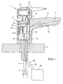
- Fig. 1 denotes a single lever mixer, for example is attached to a sink 2.
- the single lever mixer 1 is both with a cold water pipe 3 as also connected to a hot water pipe 4.
- the single-lever mixer consists of a housing part 5 with a rigid Outlet 6 with outlet channel 7 and a head piece Operating lever 8.
- the operating lever 8 is via an intermediate piece 9 and a control rod 10 with a Mixer tap 11 connected.
- the control rod is 10 via a lever arrangement 12 with the permanent magnet 13 Solenoid valves 14 mechanically connected.
- the water reaches the cold and hot water pipes 3, 4 via corresponding inlets into the mixer tap 11 there according to the position of one with the control rod 10 connected control piston (not shown) mixed and then passes from the outlet 15 of the mixer tap 11 via the Solenoid valve 14 to the outlet channel 7.
- the solenoid valve 14 (see FIG. 2) is a known pilot valve, which acts as a switching valve is used. It consists of a magnetic switching part 16 and a mechanical valve part 17.
- the switching part 16 contains a control pin 18, the lower one End extends into the valve part 17 and there one Pilot opening 19 of a piston 20 closes.
- the upper The area of the control pin 18 is made from a sleeve 21 surrounded by non-magnetic material, which in turn is within the solenoid 22 of an electromagnet 23 is arranged.
- the upper end face 24 of the control pin 18 is supported by means of a compression spring 25 on the sleeve 21.
- the side facing away from the permanent magnet 13 is the lever arrangement 12 provided with a roller 29 on one the control rod 10 attached rotationally symmetrical backdrop 30 is present.
- the backdrop essentially has three different ones Areas 31-33.
- the liquid inlets and outlets of the solenoid valve 14 are designated by the reference numerals 35 and 36.
- a proximity sensor 37 is provided (FIG. 1), which has a electrical line 38 connected to control electronics 39 is.
- the control electronics 39 is in turn over others electrical lines 40 with both a power source 41, which is accommodated in the form of a battery in the head piece 8 is also connected to the solenoid valve 14.
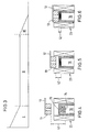
- FIGS. 3 to 6 of the single-lever mixer 1 according to the invention explained in more detail.
- Figs. 4-6 Pivotal movement of the permanent magnet 13 by displacement of the magnet in the vertical direction.
- the single-lever mixer 1 may be in its closed position Position. This means that the operating lever 8 (Fig. 1) pressed down and the mixer tap 11 is also closed.
- the distance 42 of the permanent magnet is in this position 13 from the end face 24 of the control pin 18 of the Solenoid valves 14 (Fig. 4) chosen so large that the control pin 18 after switching off the electromagnet 23 not from the permanent magnet 13 can be held and by the spring 25 is pushed into its lower switch position.
- the solenoid valve therefore only has a stable one in this case Position in which the control pin, the pilot opening 19 of the Piston 20 closes.
- An electrical opening of the solenoid valve 14, for example due to disturbance variables (e.g. while on vacation), can not.
- the control pen 18 After switching off the electromagnet 23 solely by the Magnetic force of the permanent magnet 13 against the restoring force held by the pen.
- the control pin 18 is in his upper switch position and the valve is open.
- the invention is of course not based on the above described embodiment limited. So, depending on Attachment of the operating lever to the control rod Execution of corresponding functions a reversal of the direction of movement the control rod, so that for actuation of the electrically controlled valve 14 the connecting lever 12 be adapted accordingly to this sequence of movements got to.
- the proximity sensor and electronics not necessarily are a battery arranged in the head piece 8. Rather, a power supply can also be used, which for example, is integrated in the control electronics.
- housing part with mixer tap and Valve and the outlet of the sanitary fitting are not mandatory be combined in one unit.
- bathtub fittings it has proven to be advantageous to both fittings separately on the corresponding one adjacent to the tub Arrange room wall.
Landscapes
- Health & Medical Sciences (AREA)
- Life Sciences & Earth Sciences (AREA)
- Engineering & Computer Science (AREA)
- Hydrology & Water Resources (AREA)
- Public Health (AREA)
- Water Supply & Treatment (AREA)
- Mechanically-Actuated Valves (AREA)
- Domestic Plumbing Installations (AREA)
- Multiple-Way Valves (AREA)
- Food-Manufacturing Devices (AREA)
Abstract
Description
Die Erfindung betrifft eine als Einhebelmischer ausgebildete
Sanitärarmatur gemäß den Merkmalen des Oberbegriffs des Anspruchs
1.The invention relates to a single-lever mixer
Sanitary fitting according to the features of the preamble of the
Als Einhebelmischer ausgebildete Sanitärarmaturen sind bekannt. Sie haben die früher üblichen Mischbatterien mit zwei manuell einstellbaren Ventilen für kaltes und warmes Wasser weitgehend ersetzt und bestehen üblicherweise aus einer Mischbatterie mit nur einem Betätigungshebel, der über eine Steuerstange einen in der Mischbatterie angeordneten Steuerkolben betätigt. Der Betätigungshebel ist sowohl seitlich als auch vertikal schwenkbar. Während durch die seitliche Schwenkbewegung die Mischung von kaltem und warmem Wasser vorgenommen wird, erfolgt durch die vertikale Schwenkbewegung die Regulierung der Wassermenge.Sanitary fittings designed as single-lever mixers are known. They have the mixer taps that used to be common with two manually adjustable valves for cold and warm water largely replaced and usually consist of one Mixer tap with only one operating lever, which has a Control rod a control piston arranged in the mixer tap operated. The operating lever is on both sides can also be swiveled vertically. While through the side Swiveling the mixture of cold and warm water is carried out by the vertical pivoting movement regulating the amount of water.
Bei den bekannten Einhebelmischern erfolgt sowohl die Ein- und Ausschaltung der Armatur als auch die Temperaturwahl und Mengenregulierung des Wassers manuell. Dieses hat sich als nachteilig erwiesen, weil eine einmal eingestellte optimale Wassertemperatur oder ein einmal als optimal eingestellter Volumenstrom nach jedem Schließen der Armatur immer wieder mühselig neu eingestellt werden muß. Für derartige Einstellungen wird eine erhebliche Menge von ungenutztem Wasser benötigt.In the known single lever mixers, both the and switching off the valve as well as the temperature selection and Quantity regulation of the water manually. This has proven to be proven disadvantageous because a once set optimal Water temperature or a once set as optimal Volume flow every time the valve is closed laboriously readjusted. For such settings a significant amount of unused water is required.
Insbesondere aus hygienischen Gründen (stark verschmutzte Hände, Gefahr der Übertragung von Krankheitserregern in öffentlichen Toiletten etc.) ist es außerdem wünschenswert, den Einhebelmischer auch berührungslos betätigen zu können.Especially for hygienic reasons (heavily soiled Hands, risk of transmission of pathogens in public Toilets, etc.) it is also desirable that Single-lever mixer can also be operated without contact.
Eine als Einhebelmischer ausgebildete Sanitärarmatur nach dem
Oberbegriff des Anspruchs 1 ist aus der US-A-5,358,213 bekannt.
Bei diesem bekannten Einhebelmischer ist jedoch eine
selbsttätige Betätigung zum Öffnen des Ventils nur in der geschlossenen
Endstellung des Betätigungshebels möglich, da in
sämtlichen anderen manuell eingestellten Stellungen das das
elektrische Öffnen ermöglichende Spiel zwischen den Betätigungsorganen
aufgehoben ist.A sanitary fitting designed as a single lever mixer after
The preamble of
Aus der DE 25 33 527 A1 ist eine Sanitärarmatur mit zwei manuell verstellbaren Ventilen für kaltes und warmes Wasser bekannt, wobei in den Auslaufkanal ein Magnetventil eingeschaltet ist. Dieses wird über einen Näherungsschalter mittels einer Steuerelektronik betätigt, sobald ein Gegenstand in den Überwachungsbereich des Näherungsschalters gelangt. Abgesehen von dem nicht sehr ansprechenden Aufbau einer derartigen berührungslos gesteuerten Sanitärarmatur, bei der Teile des Magnetventils sowie elektrische Leitungen gut sichtar auf dem Auslaufteil montiert sind, weist diese Armatur den Nachteil auf, daß ein manuelles Ein- und Ausschalten, wie bei herkömmlichen manuell betätigbaren Armaturen, nicht mehr möglich ist. Fällt also die Stromversorgung des Magnetventiles aus irgend einem Grunde aus, kann der Armatur kein Wasser mehr entnommen werden. From DE 25 33 527 A1 a sanitary fitting with two is manual adjustable valves for cold and warm water known with a solenoid valve turned on in the outlet channel is. This is done using a proximity switch a control electronics operated as soon as an object enters the monitoring area of the proximity switch. Apart from the not very attractive structure of such a non-contact controlled sanitary fitting at the Parts of the solenoid valve and electrical lines are good are mounted on the spout, this valve has the disadvantage that manual switching on and off, as with conventional manually operated fittings, is no longer possible. So the power supply drops of the solenoid valve for any reason, the armature no more water can be removed.
Ausgehend von einem Einhebelmischer nach dem Oberbegriff des
Anspruchs 1 liegt der Erfindung die Aufgabe zugrunde, diesen
dahingehend weiterzubilden, daß über das Verschwenken des Betätigungshebels
in vertikaler Richtung die elektronische
Steuerung ausgeschaltet werden kann.Starting from a single lever mixer according to the generic term of
Diese Aufgabe wird erfindungsgemäß durch die Merkmale des
kennzeichnenden Teils des Anspruchs 1 gelöst. Weitere, besonders
vorteilhafte Ausgestaltungen der Erfindung offenbaren
die Unteransprüche. This object is achieved by the features of
characterizing part of
Die Erfindung beruht im wesentlichen auf dem Gedanken, der Mischbatterie des Einhebelmischers ein elektrisch steuerbares Ventil nachzuschalten, dessen Funktion nicht nur von den Schaltsignalen der Steuerelektronik abhängt, sondern auch von der Stellung des Betätigungshebels der Armatur. Hierzu sind vorzugsweise die mit dem Betätigungshebel verbundene Steuerstange und das elektrisch steuerbare Ventil derart mechanisch miteinander gekoppelt, daß das Ventil einerseits trotz entsprechender von dem Annäherungssensor erzeugter Öffnungssignale etc. geschlossen bleibt, sofern auch die Mischbatterie geschlossen ist (der Betätigungshebel der Armatur befindet sich in der Regel in seiner unteren Lage). Andererseits bleibt das elektrisch steuerbare Ventil auch ohne entsprechende Öffnungssignale des Annäherungssensors geöffnet, sofern die Mischbatterie durch Betätigung der Steuerstange vollständing geöffnet ist (der Hebel der Armatur befindet sich in der Regel in seiner oberen Lage).The invention is essentially based on the idea that Single-lever mixer tap an electrically controllable Downstream valve, its function not only by the Switching signals of the control electronics depends, but also on the position of the operating lever of the valve. For this are preferably the control rod connected to the actuating lever and the electrically controllable valve mechanically coupled that the valve on the one hand despite the corresponding opening signals generated by the proximity sensor etc. remains closed, provided that the mixer tap is closed (the operating lever of the valve is located usually in its lower position). On the other hand the electrically controllable valve remains without a corresponding one Opening signals from the proximity sensor opened, if the mixer tap by operating the control rod is fully open (the valve lever is located usually in its upper position).
In einem vorgebbaren Bereich zwischen der geschlossenen und der vollständig geöffneten Stellung der Mischbatterie erfolgt ein Öffnen und Schließen des elektrisch steuerbaren Ventils allein durch die von dem Annäherungssensor erzeugten und von der Steuerelektronik aufbereiteten Steuersignale.In a predeterminable range between the closed and the mixer tap is fully open opening and closing of the electrically controllable valve solely by those generated by the proximity sensor and by the control electronics prepared control signals.
Fällt bei dem erfindungsgemäßen Einhebelmischer daher die Stromversorgung der Steuerelektronik aus, so kann mit der Armatur trotzdem Wasser gezapft werden, indem der Hebel von der geschlossenen Stellung der Mischbatterie in die vollständig geöffnete Stellung verschwenkt wird. Damit in dieser Stellung das Wasser nicht schlagartig in das entsprechende Becken spritzt, hat es sich als vorteilhaft erwiesen, den Steuerkolben und die den Steuerkolben umgebende Kartuschenhülse der Mischbatterie derart auszugetalten, daß bei der vollständig geöffneten Stellung der Mischbatterie eine Reduzierung des Flüssigkeitsflusses erfolgt.Therefore falls in the single-lever mixer according to the invention Power supply to the control electronics can be done with the valve water can still be tapped by pulling the lever from the closed position of the mixer tap in the fully open position is pivoted. So in this position the water did not suddenly enter the corresponding pool injected, it has proven advantageous to the control piston and the cartridge sleeve surrounding the control piston Mixer tap in such a way that the complete open position of the mixer tap a reduction in Liquid flow takes place.
Auf besonders einfache und vorteilhafte Weise läßt sich die mechanische Ansteuerung des Ventiles in Abhängigkeit von der Stellung der Steuerstange erreichen, wenn es sich bei dem elektrisch steuerbaren Ventil um ein an sich bekanntes Magnetventil handelt. Derartige Magnetventile bestehen aus einem magnetischen Schaltteil und einem mechanischen Ventilteil. Dabei weist das magnetische Schaltteil einen zur Öffnung und zum Schließen des Ventiles vorhandenen Steuerstift auf, der von einem Elektromagneten gegen den Druck einer Feder axial verschiebbar angeordnet ist. Ferner ist ein Permanentmagnet vorgesehen, der den Steuerstift nach Abschalten des Elektromagneten in seiner gegen den Druck der Feder verschobenen Stellung hält.In a particularly simple and advantageous manner, the mechanical control of the valve depending on the Reach the position of the control rod if it is electrically controllable valve around a known solenoid valve acts. Such solenoid valves consist of a magnetic switching part and a mechanical valve part. The magnetic switching part has one for opening and existing control pin to close the valve on by an electromagnet against the pressure of a spring is axially displaceable. Also a permanent magnet provided the control pin after switching off of the electromagnet in its shifted against the pressure of the spring Holds position.
Um zu erreichen, daß das Magnetventil in der geschlossenen Stellung der Mischbatterie trotz Bestromung der entsprechenden Magnetspulen geschlossen bzw. ohne Bestromung der entsprechenden Magnetspulen geöffnet bleibt, sofern die Mischbatterie vollständig geöffnet ist, ist erfindungsgemäß die Steuerstange mit dem Pemanentmagnet des magnetischen Schaltteiles mechanisch über mindestens einen Hebel verbunden. Wird die axiale Lage der Steuerstange verändert, so verschiebt sich daher auch der Permanentmagnet und verändert seinen Abstand in bezug auf den Steuerstift des Schaltteiles, und zwar derart, daß in der geschlossenen Stellung der Mischbatterie der Permanentmagnet keine funktionsrelevante Wirkung mehr auf den Steuerstift ausübt und in der vollständig geöffneten Stellung der Steuerstange der Dauermagnet den Steuerstift ständig anzieht.To achieve that the solenoid valve in the closed Position of the mixer tap despite energizing the corresponding one Magnetic coils closed or without energizing the corresponding Solenoid coil remains open provided the mixer tap is fully open, is the invention Control rod with the permanent magnet of the magnetic switching part mechanically connected via at least one lever. Becomes the axial position of the control rod changed, so it shifts the permanent magnet also changes and changes its distance with respect to the control pin of the switching part, namely such that in the closed position of the mixer tap the permanent magnet no longer has a functionally relevant effect exerts the control pin and in the fully open Position of the control rod of the permanent magnet the control pin constantly attracts.
Bei einem vorteilhaften Ausführungsbeispiel der Erfindung ist der Hebel als Umlenkhebel ausgestaltet, so daß ein Ziehen der Steuerstange eine Bewegung des Permanentmagneten zu dem Steuerstift hin bewirkt, wobei die gegenseitige Bewegung von Steuerstange und Permanentmagnet durch eine an der Steuerstange angeordnete Kulisse festgelegt wird, an welcher das eine Ende des Umlenkhebels entlanggleitet.In an advantageous embodiment of the invention the lever is designed as a lever, so that pulling the Control rod movement of the permanent magnet to the control pin towards, the mutual movement of Control rod and permanent magnet through one on the control rod arranged backdrop is set on which the sliding along one end of the bellcrank.
Damit das Magnetventil bei der Steuerung des Durchflusses nur eine geringe Kraft ausführen muß, hat es sich als vorteilhaft erwiesen, ein vorgesteuertes (pilotgesteuertes) Ventil zu verwenden, bei dem eine Membran oder ein Kolben vorgesehen ist, welche(r) sich unter der Wirkung der beidseits anstehenden Wasserdrücke relativ zum Ventilsitz bewegt und eine Pilotöffnung aufweist. Zur Ansteuerung des Ventiles wird die Pilotöffnung durch den von dem Elektromagneten des Schaltteiles betätigbaren Steuerstift geöffnet oder geschlossen.So the solenoid valve only when controlling the flow a small force, it has proven to be advantageous proven to have a pilot operated (pilot operated) valve use a membrane or piston is which is under the effect of the two sides Water pressures moved relative to the valve seat and a pilot opening having. To control the valve, the Pilot opening through the electromagnet of the switching part actuatable control pin opened or closed.
Ein wesentlicher Vorteil des erfindungsgemäßen Einhebelmischers besteht darin, daß unabhängig davon, ob die Armatur berührungslos betrieben wird oder etwa bei Stromausfall rein manuell betrieben wird, die Mischfunktion der Armatur nicht beeinträchtigt wird.A major advantage of the single lever mixer according to the invention is that regardless of whether the fitting is operated without contact or in the event of a power failure is operated manually, the mixing function of the valve is not is affected.
Ein weiterer wesentlicher Vorteil ist darin zu sehen, daß die bei herkömmlichen Einhebelmischern erforderliche aufwendige Abdichtung mittels relativ teuerer Keramikdichtscheiben entfallen kann. Denn an die Abdichtungsfunktion der Mischbatterie in seiner geschlossenen Stellung können geringe Anforderungen gestellt werden, weil für eine einwandfreie Abdichtung das nachgeschaltete Magnetventil verantwortlich ist.Another major advantage is that the required with conventional single lever mixers Sealing by means of relatively expensive ceramic sealing washers is not necessary can. Because of the sealing function of the mixer tap in its closed position can be low requirements be put because of a perfect seal the downstream solenoid valve is responsible.
Als besonders vorteilhaft hat es sich ferner erwiesen, daß eine mit dem erfindungsgemäßen Einhebelmischer nicht vertraute Person auch dann Wasser zapfen kann, wenn sie im Falle des berührungslosen Betriebes der Armatur das elektrisch steuerbare Ventil mittels des Annäherungssensors nicht aktiviert. Denn eine derartige Person wird den Einhebelmischer in konventioneller Weise durch Verschwenken des Betätigungshebels bedienen und erhält in der Endstellung des Hebels ebenfalls Wasser, weil das Ventil durch die mechanische Verstellung des Permanentmagneten geöffnet wird.It has also proven to be particularly advantageous that a not familiar with the single-lever mixer according to the invention Person can tap water even if they are in the case of contactless operation of the valve the electrically controllable Valve not activated using the proximity sensor. Because such a person becomes the single-lever mixer in conventional Way by pivoting the operating lever operate and also receives in the end position of the lever Water because the valve by the mechanical adjustment of the Permanent magnet is opened.
Aus ästhetischen Gründen, aber auch aus Sicherheitsgründen hat es sich ferner als vorteilhaft erwiesen, wenn das elektrisch steuerbare Ventil einschließlich der elektrischen Steuerleitungen innerhalb des Gehäuses des Einhebelmischers angeordnet sind. Diese Teile sind daher von außen nicht sichtbar.For aesthetic reasons, but also for security reasons it has also proven to be advantageous if this is electrical controllable valve including electrical Control lines inside the housing of the single lever mixer are arranged. These parts are therefore not from the outside visible.
Weitere Einzelheiten und Vorteile der Erfindung ergeben sich aus den folgenden anhand von Figuren erläuterten Ausführungsbeispielen. Es zeigen:
- Fig. 1
- einen Längsschnitt durch einen erfindungsgemäßen Einhebelmischer mit schematisch angedeuteter Mischbatterie und einem Magnetventil, welche beide durch die gleiche Steuerstange betätigbar sind;
- Fig. 2
- einen Teilschnitt durch ein erstes Ausführungsbeispiel eines Magnetventiles mit verschwenkbarem Permanentmagnet, welcher über einen Umlenkhebel mit der Steuerstange verbunden ist;
- Fig. 3
- ein Diagramm, welches die Lage des Permanentmagneten des Magnetventiles in Abhängigkeit von der Stellung der Steuerstange wiedergibt und
- Fig. 4-6
- schematisch die den einzelnen in Fig. 3 mit I-III bezeichneten Bereichen entsprechenden Stellungen des Permanentmagneten in bezug auf den Steuerstift des Magnetventiles.
- Fig. 1
- a longitudinal section through a single-lever mixer according to the invention with a schematically indicated mixer tap and a solenoid valve, both of which can be actuated by the same control rod;
- Fig. 2
- a partial section through a first embodiment of a solenoid valve with pivotable permanent magnet, which is connected to the control rod via a bell crank;
- Fig. 3
- a diagram showing the position of the permanent magnet of the solenoid valve as a function of the position of the control rod and
- Fig. 4-6
- schematically the positions of the permanent magnet corresponding to the individual areas designated by I-III in FIG. 3 with respect to the control pin of the solenoid valve.
In Fig. 1 ist mit 1 ein Einhebelmischer bezeichnet, der beispielsweise
an einem Waschbecken 2 befestigt ist. Der Einhebelmischer
1 ist sowohl mit einer Kaltwasserleitung 3 als
auch mit einer Warmwasserleitung 4 verbunden.In Fig. 1, 1 denotes a single lever mixer, for example
is attached to a
Der Einhebelmischer besteht aus einem Gehäuseteil 5 mit starrem
Auslauf 6 mit Auslaufkanal 7 und einem als Kopfstück ausgebildeten
Betätigungshebel 8. Der Betätigungshebel 8 ist
über ein Zwischenstück 9 und eine Steuerstange 10 mit einer
Mischbatterie 11 verbunden. Außerdem ist die Steuerstange 10
über eine Hebelanordnung 12 mit dem Permanentmagnet 13 eines
Magnetventiles 14 mechanisch verbunden.The single-lever mixer consists of a
Von den Kalt- und Warmwasserleitungen 3, 4 gelangt das Wasser
über entsprechende Einläufe in die Mischbatterie 11, wird
dort entsprechend der Stellung eines mit der Steuerstange 10
verbundenen Steuerkolbens (nicht dargestellt) gemischt und
gelangt dann von dem Auslauf 15 der Mischbatterie 11 über das
Magnetventil 14 zu dem Auslaufkanal 7. The water reaches the cold and
Bei dem Magnetventil 14 (vgl. Fig. 2) handelt es sich um ein
an sich bekanntes Vorsteuerventil, welches als Schaltventil
benutzt wird. Es besteht aus einem magnetischen Schaltteil 16
und einem mechanischen Ventilteil 17.The solenoid valve 14 (see FIG. 2) is a
known pilot valve, which acts as a switching valve
is used. It consists of a
Das Schaltteil 16 enthält einen Steuerstift 18, dessen unteres
Ende sich bis in das Ventilteil 17 erstreckt und dort eine
Pilotöffnung 19 eines Kolbens 20 verschließt. Der obere
Bereich des Steuerstiftes 18 wird von einer Hülse 21 aus
nichtmagnetischem Material umgeben, die ihrerseits innerhalb
der Zylinderspule 22 eines Elektromagneten 23 angeordnet ist.
Die obere Stirnseite 24 des Steuerstiftes 18 stützt sich mittels
einer Druckfeder 25 an der Hülse 21 ab.The switching
Der Permanentmagnet 13, der erfindungsgemäß an dem Umlenkhebel
12 befestigt ist, ist um eine Achse 26 schwenkbar an einem
Ausleger 27 des Magnetventiles 14 angeordnet. Auf seiner,
dem Permanentmagneten 13 abgewandten Seite 28 ist die Hebelanordnung
12 mit einer Rolle 29 versehen, die an einer an
der Steuerstange 10 befestigten rotationssymmetrischen Kulisse
30 anliegt. Die Kulisse weist im wesentlichen drei unterschiedliche
Bereiche 31-33 auf.The
Wird die Steuerstange 10 in Richtung des Pfeiles 34 gezogen,
so verändert sich die Lage der Umlenkhebelanordnung 12 und
damit auch des Permanentmagneten 13 so lange nicht, wie sich
die Rolle 29 in dem Bereich 31 der Kulisse 30 abstützt. In
den Bereichen 32 bzw. 33 hingegen wird der Permanentmagnet 13
in Richtung auf den Steuerstift 18 hin- bzw. von dem Steuerstift
18 weggeschwenkt. Wie nachfolgend anhand der Fig. 3-6
noch erläutert werden wird, verliert das Magnetventil 14 in
diesen Stellungen sein bistabiles Verhalten. If the
Die Flüssigkeitsein- und -ausläufe des Magnetventiles 14 sind
mit den Bezugszeichen 35 und 36 bezeichnet.The liquid inlets and outlets of the
Auf der Unterseite des Auslaufs 6 des Einhebelmischers 1 ist
ein Annäherungssensor 37 vorgesehen (Fig. 1), der über eine
elektrische Leitung 38 mit einer Steuerelektronik 39 verbunden
ist. Die Steuerelektronik 39 ist ihrerseits über weitere
elektrische Leitungen 40 sowohl mit einer Stromversorgungsquelle
41, die in Form einer Batterie in dem Kopfstück 8 untergebracht
ist, als auch mit dem Magnetventil 14 verbunden.On the underside of the
Im folgenden wird anhand der Fig. 3 bis 6 die Wirkugnsweise
des erfindungsgemäßen Einhebelmischers 1 näher erläutert. Dabei
wurde zur einfacheren Darstellung in den Fig. 4-6 die
Schwenkbewegung des Permanentmagneten 13 durch eine Verschiebung
des Magneten in vertikaler Richtung ersetzt.In the following, the mode of action is shown in FIGS. 3 to 6
of the single-
Zunächst möge sich der Einhebelmischer 1 in seiner geschlossenen
Stellung befinden. Dieses bedeutet, daß der Betätigungshebel
8 (Fig. 1) nach unten gedrückt und die Mischbatterie
11 ebenfalls geschlossen ist.First, the single-
Außerdem ist in dieser Stellung der Abstand 42 des Permanentmagneten
13 von der Stirnseite 24 des Steuerstiftes 18 des
Magnetventiles 14 (Fig. 4) so groß gewählt, daß der Steuerstift
18 nach dem Abschalten des Elektromagneten 23 nicht von
dem Permanentmagnet 13 gehalten werden kann und durch die Feder
25 in seine untere Schaltstellung geschoben wird. Das Magnetventil
besitzt in diesem Fall daher nur eine stabile
Stellung, bei der der Steuerstift die Pilotöffnung 19 des
Kolbens 20 verschließt. Ein elektrisches Öffnen des Magnetventiles
14, etwa durch Störgrößen (z.B. während der Urlaubsabwesenheit),
ist nicht möglich.In addition, the
Bei einem allmählichen Hochschwenken des Betätigungshebels 8
bleibt das Magnetventil 14 auch innerhalb des in Fig. 3 mit I
bezeichneten Schwenkbereiches, der dem in Fig. 2 mit 33 bezeichneten
Kulissenbereich entspricht, weiterhin geschlossen.When the operating
Verringert sich der Abstand 42 zwischen Permanentmagnet 13
und Steuerstift 18 durch Ziehen des Betätigungshebels 8 weiter,
so wird der in Fig. 3 mit II bezeichnete Schwenkbereich
des Betätigungshebels erreicht, der dem Kulissenbereich 31
entspricht. Innerhalb dieses Bereiches wird der Steuerstift
18 nach Abschalten des Elektromagneten 23 allein durch die
Magnetkraft des Permanentmagneten 13 gegen die Rückstellkraft
der Feder gehalten. Der Steuerstift 18 befindet sich in seiner
oberen Schaltstellung und das Ventil ist geöffnet.The
Das Zurücksteuern des Steuerstiftes 18 in seine untere
Schaltstellung erfolgt durch erneute Aktivierung des Elektromagneten
23, der nach Umschalten der Stromrichtung dem Permanentmagnet
13 entgegenwirkt. Die dadurch erreichte geschlossene
Stellung des Magnetventiles 14 ist ebenfalls stabil, da
die Kraft der Feder 25 größer ausgelegt ist als die bei diesem
Abstand verbleibende Anziehungskraft des Permanentmagneten
13. In dem Schwenkbereich II arbeitet das Magnetventil 14
daher bistabil.Controlling the
In dem in Fig. 3 mit III bezeichneten Schwenkbereich, der in
Fig. 2 dem Kulissenbereich 32 entspricht, ist der Abstand 42
des Permanentmagneten 13 so klein, daß der Steuerstift 18
ständig durch die Magnetkraft des Permanentmagneten 13 gegen
die Kraft der Feder 25 in dieser Lage verbleibt. Ein elektrisches
Schließen des Magnetventiles ist nicht möglich. Das
Ventil besitzt nur eine stabile Lage.In the swivel range designated by III in FIG
2 corresponds to the
Die Erfindung ist selbstverständlich nicht auf das vorstehend
beschriebene Ausführungsbeispiel beschränkt. So kann, je nach
Befestigung des Betätigungshebels, an der Steuerstange zur
Ausführung entsprechender Funktionen eine Umkehr der Bewegungsrichtung
der Steuerstange erfolgen, so daß zur Betätigung
des elektrisch gesteuerten Ventiles 14 der Verbindungshebel
12 diesem Bewegungsablauf entsprechend angepaßt werden
muß.The invention is of course not based on the above
described embodiment limited. So, depending on
Attachment of the operating lever to the control rod
Execution of corresponding functions a reversal of the direction of movement
the control rod, so that for actuation
of the electrically controlled
Außerdem braucht es sich bei der Stromversorgung für das Ventil,
den Annäherungssensor und die Elektronik nicht notwendigerweise
um eine in dem Kopfstück 8 angeordnete Batterie handeln.
Vielmehr kann auch ein Netzgerät verwendet werden, welches
beispielsweise in die Steuerelektronik integriert ist.It also needs power for the valve,
the proximity sensor and electronics not necessarily
are a battery arranged in the
Als besonders vorteilhaft hat es sich ferner erwiesen, wenn
die Mischbatterie 11 und das elektrisch steuerbare Ventil 14
in einer auswechselbaren Kartusche angeordnet sind. Dadurch
ist einerseits ein einfacher und kostensparender Zusammenbau
der Armatur möglich. Andererseits läßt sich die Armatur bei
Störungen der Mischbatterie oder des Ventiles durch Austausch
der Kartusche schnell reparieren. Eine entsprechende schematisch
dargestellte Kartusche ist in Fig. 1 mit dem Bezugszeichen
43 versehen.It has also proven to be particularly advantageous if
the
Schließlich brauchen das Gehäuseteil mit Mischbatterie und Ventil und der Auslauf der Sanitärarmatur nicht zwingend in einer Einheit zusammengefaßt sein. Insbesondere bei Badewannenarmaturen hat es sich als vorteilhaft erwiesen, beide Armaturteile getrennt an der entsprechenden an die Wanne angrenzenden Zimmerwand anzuordnen. Finally need the housing part with mixer tap and Valve and the outlet of the sanitary fitting are not mandatory be combined in one unit. Especially with bathtub fittings it has proven to be advantageous to both fittings separately on the corresponding one adjacent to the tub Arrange room wall.
- 11
- EinhebelmischerSingle lever mixer
- 22nd
- Waschbeckensink
- 33rd
- KaltwasserleitungCold water pipe
- 44th
- WarmwasserleitungHot water pipe
- 55
- GehäuseteilHousing part
- 66
- AuslaufSpout
- 77
- AuslaufkanalOutlet channel
- 88th
- Betätigungshebel, KopfstückActuation lever, head piece
- 99
- ZwischenstückSpacer
- 1010th
- SteuerstangeControl rod
- 1111
- MischbatterieMixer tap
- 1212th
- Umlenkhebel, HebelBell crank, lever
- 1313
- PermanentmagnetPermanent magnet
- 1414
- Magnetventil, elektrisch steuerbares VentilSolenoid valve, electrically controllable Valve
- 1515
- Auslauf (Mischbatterie)Spout (mixer tap)
- 1616
- magnetisches Schaltteilmagnetic switching part
- 1717th
- mechanisches Ventilteilmechanical valve part
- 1818th
- SteuerstiftControl pin
- 1919th
- PilotöffnungPilot opening
- 2020th
- Kolbenpiston
- 2121
- HülseSleeve
- 2222
- ZylinderspuleSolenoid
- 2323
- ElektromagnetElectromagnet
- 2424th
- StirnseiteFace
- 2525th
- Feder, DruckfederSpring, compression spring
- 2626
- Achseaxis
- 2727
- Ausleger boom
- 2828
- Seitepage
- 2929
- Rollerole
- 3030th
- KulisseBackdrop
- 31-3331-33
- KulissenbereicheBackdrop areas
- 3434
- Pfeilarrow
- 3535
- FlüssigkeitseinlaufFluid intake
- 3636
- FlüssigkeitsauslaufLiquid outlet
- 3737
- AnnäherungssensorProximity sensor
- 3838
- elektrische Leitungelectrical line
- 3939
- SteuerelektronikControl electronics
- 4040
- elektrische Leitungelectrical line
- 4141
- StromversorgungsquellePower source
- 4242
- Abstanddistance
- 4343
- auswechselbare Kartuscheexchangeable cartridge
Claims (9)
- Sanitary fitting performed as a single-lever mixer having a housing part (5) and an exit part (6) containing the exit channel (7), wherein in the housing part (5) a mixer tap (11) for mixing cold and warm fluid and for controlling the flow rate is positioned and is actuable between a closed final position and an opened final position by the means of a control rod (10) being connected to an actuating lever (8), wherein an electrically controllable valve (14) is fitted downstream of the mixer tap (11) by the means of which the fluid emanating from the mixer tap (11) before entering into the exit channel is guided, wherein the electrically control valve (14) by the means of a control electronic circuit (39) is connected to a proximity sensor (37) and, wherein the electrically controllable valve (14) additionally can be controlled mechanically by means of the actuating lever (8) via the control rod (10), characterized in that a lever arrangement (12) is provided between the control rod (10) and the electrically controllable valve (14) which mechanically is adjusting the electrically controllable valve (14) in such a waya) that in the closed end position of the mixer tap (11) or within a first pivot range (I) of the actuating lever (8) following said end position respectively, in spite of electric control signals applied to the electrically controllable valve (14) the valve (14) is remaining closed,b) that in the completely opened final position of the mixer tap (11) or within a third pivot range (III) preceding said end position the valve (14) is remaining opened, too, in spite of electric control signals applied to the valve (14) and,c) that within a second pivot range (II) of the actuating lever (8) being positioned between the first and the third range the electrically controllable valve (14) is remaining closed and is opened only by the means of activation by the proximity sensor (37).
- Single-lever mixer according to claim 1, characterized in that the electrically controllable valve (14) is a solenoid valve having a magnetic switch member (16) and a mechanic valve member (17),that the magnetic switch member (16) is having a control pin (18) acting on the valve member (17), said control pin (18) being axially displaceable by an electromagnet (23) against the pressure of a spring (25),that above the side of the control pin (18) being distant from the valve member (17) a permanent magnet (13) is provided which by means of the lever arrangement (12) is connected to the control rod (10) in such a way that the distance (42) of the permanent magnet (13) with respect to the control pin (18) can be changed corresponding to the axial position of the control rod (10) in such a way that in the closed position of the mixer tap (11) or in the first pivot range (1) of the actuating lever (8) respectively, the permanent magnet (13) has no more any effect on the control pin (18) being relevant to function,that in the completely opened position of the mixer tap (11) or in the third pivot range (III) of the actuating lever (8), respectively, the permanent magnet (13) continuously is attracting the control pin (18) and,in that the solenoid valve (14) in the second pivot range (II) of the actuating lever is working in a bistable manner and the control pin (18) after switching of the electromagnet (23), in dependence from the previous direction of the current in the electromagnet (23) either is maintained in the closed position of the valve by the force of the spring (25) or is maintained in the opened valve position by the magnetic force of the permanent magnet (13).
- Single-lever mixer according to claim 2, characterized in that the lever arrangement (12) is performed as a reversing lever the side (28) of which being distant from the permanent magnet (13) being guided by a gate (30) pivotably connected to the control rod (10) in such a way that the electromagnet (23) in the individual pivot ranges (I - III) is adopting the necessary positions for the corresponding functions of the solenoid valve (14).
- Single-lever mixer according to claim 2 or 3, characterized in that the solenoid valve (14) is performed as a pilot valve, the pilot opening (19) of which can be closed by the control pin (18).
- Single-lever mixer according to any of the claims 1 to 4, characterized in that the control piston and the shell enclosing the control piston of the mixer tap (11) are performed such that in the completely opened position of the mixer tap (11) a reducing of the fluid flow is occurring.
- Single-lever mixer according to any of the claims 1 to 5, characterized in that the electrically controllable valve (14) is completely positioned within the housing part (5) of the single-lever mixer (1).
- Single-lever mixer according to any of the claims 1 to 6, characterized in that the mixer tap (11) and the electrically controllable valve (14) are positioned within a replaceable shell (43).
- Single-lever mixer according to any of the claims 1 to 7, characterized in that the proximity sensor (37) being positioned on the bottom side of the exit part (7) by the means of a electric line extending within the housing part (5) is connected to the control circuit (39).
- Single-lever mixer according to claim 8, characterized in that for the current supply of the proximity sensor (37), the control circuit (39) and the electrically controllable valve (14) there is provided a storage battery (41) and, in that the storage battery replaceably is positioned in the head piece (18) of the single-lever mixer (1).
Applications Claiming Priority (3)
| Application Number | Priority Date | Filing Date | Title |
|---|---|---|---|
| DE19623104 | 1996-06-10 | ||
| DE19623104A DE19623104C2 (en) | 1996-06-10 | 1996-06-10 | Sanitary fitting designed as a single lever mixer |
| PCT/DE1997/001164 WO1997047828A1 (en) | 1996-06-10 | 1997-06-09 | Sanitary fitting in the form of a single-lever mixer tap |
Publications (2)
| Publication Number | Publication Date |
|---|---|
| EP0904469A1 EP0904469A1 (en) | 1999-03-31 |
| EP0904469B1 true EP0904469B1 (en) | 2000-05-17 |
Family
ID=7796526
Family Applications (1)
| Application Number | Title | Priority Date | Filing Date |
|---|---|---|---|
| EP97926994A Expired - Lifetime EP0904469B1 (en) | 1996-06-10 | 1997-06-09 | Sanitary fitting in the form of a single-lever mixer tap |
Country Status (8)
| Country | Link |
|---|---|
| US (1) | US6044865A (en) |
| EP (1) | EP0904469B1 (en) |
| JP (1) | JP2000512352A (en) |
| AT (1) | ATE193074T1 (en) |
| AU (1) | AU3164997A (en) |
| DE (2) | DE19623104C2 (en) |
| ES (1) | ES2150261T3 (en) |
| WO (1) | WO1997047828A1 (en) |
Families Citing this family (23)
| Publication number | Priority date | Publication date | Assignee | Title |
|---|---|---|---|---|
| DE29800536U1 (en) * | 1998-01-16 | 1998-03-05 | A. u. K. Müller GmbH & Co KG, 40595 Düsseldorf | Solenoid valve, especially for sanitary fittings |
| DE19803817C5 (en) * | 1998-01-31 | 2005-11-03 | Meloh Armaturen Ruppel & Meloh Gmbh | Fitting, in particular water fitting |
| DE29824484U1 (en) | 1998-10-12 | 2001-03-29 | KLUDI-Armaturen Scheffer Vertriebs- und Verwaltungs oHG, 58706 Menden | Cartridge for a single lever water mixer tap |
| DE19846720A1 (en) | 1998-10-12 | 2000-04-13 | Kludi Armaturen Scheffer Vertr | A water mixer valve has a lever which enables manual or electric operation. |
| IT1314778B1 (en) | 2000-01-25 | 2003-01-16 | Nuova Galatron Srl | DEVICE FOR AUTOMATIC WATER DISPENSING |
| IT1314777B1 (en) * | 2000-01-25 | 2003-01-16 | Nuova Galatron Srl | WATER DISPENSING AND MIXING DEVICE |
| DE10005961A1 (en) * | 2000-02-09 | 2001-08-16 | Grohe Armaturen Friedrich | Water outlet device |
| DE10156736A1 (en) | 2001-11-19 | 2003-06-05 | World Of Medicine Lemke Gmbh | Device for the manual, contactless actuation of an electrical device |
| US7537023B2 (en) | 2004-01-12 | 2009-05-26 | Masco Corporation Of Indiana | Valve body assembly with electronic switching |
| DE102005012704B4 (en) * | 2005-03-11 | 2007-06-06 | Hansa Metallwerke Ag | Mixing faucet |
| EP1876305A1 (en) * | 2006-07-07 | 2008-01-09 | Hsiang Hung Wang | Mixing faucet with switching from automatic to manual control |
| WO2009103596A1 (en) | 2008-02-20 | 2009-08-27 | Edo Lang | Control device for plumbing appliances |
| US8302932B2 (en) * | 2009-03-07 | 2012-11-06 | John Sam Bakke | Sprinkler valve test and control device and method thereof |
| DE102009051090B4 (en) | 2009-10-28 | 2012-01-26 | Grohe Ag | plumbing fixture |
| US8820705B2 (en) | 2011-07-13 | 2014-09-02 | Masco Corporation Of Indiana | Faucet handle with angled interface |
| US11091901B2 (en) | 2011-07-13 | 2021-08-17 | Delta Faucet Company | Faucet handle with angled interface |
| DE102013011598B4 (en) * | 2013-07-11 | 2017-02-23 | Grohe Ag | Sanitary fitting with mixing shaft |
| EP3092080B1 (en) * | 2014-01-09 | 2023-08-02 | Beyer, Hans-Jörgen | Valve comprising a variable flow opening |
| CN105546138B (en) * | 2016-01-22 | 2017-12-26 | 林秀东 | Flow can be adjusted for one kind and default tap |
| DE102016106411B4 (en) | 2016-04-07 | 2024-07-18 | Samson Aktiengesellschaft | Electropneumatic solenoid valve |
| CN110296261B (en) * | 2019-05-16 | 2024-11-22 | 厦门建霖健康家居股份有限公司 | Faucet and operating method thereof |
| DE102020104068A1 (en) | 2020-02-17 | 2021-08-19 | Grohe Ag | Sanitary device on whose actuating element a magnetic force can be perceived haptically |
| CN112377642B (en) * | 2020-11-11 | 2022-07-05 | 厦门大白科技有限公司 | Control valve group and have its tap and shower |
Family Cites Families (8)
| Publication number | Priority date | Publication date | Assignee | Title |
|---|---|---|---|---|
| AT233341B (en) * | 1961-09-04 | 1964-05-11 | Kromschroeder Ag G | Valve |
| DE2533527A1 (en) * | 1975-07-26 | 1977-01-27 | Dalferth Gotthilf R | Liq. dispensing equipment for shower head - has solenoid valve controlled by proximity switch monitoring area below water outlet |
| GB2141597B (en) * | 1983-06-14 | 1987-02-11 | Dobson Park Ind | Electrically operated valve |
| EP0245577B1 (en) * | 1986-05-12 | 1990-04-11 | D.M.P. Electronics Soc.r.l. | Tap for the delivery of liquids for the conversion from automatic to manual |
| GB2206397A (en) * | 1987-07-01 | 1989-01-05 | Chong Lih Electric Industry Co | Photoelectrically-controlled faucet structure |
| US5358213A (en) * | 1993-03-31 | 1994-10-25 | Pilolla Joseph J | Faucet having automatic and manual control capability |
| DE4420331A1 (en) * | 1994-06-10 | 1995-12-14 | Grohe Armaturen Friedrich | Water fitting esp. non-contact controlled water feed fitting with fitting body |
| US5529281A (en) * | 1994-08-24 | 1996-06-25 | The United States Of America As Represented By The Administrator Of National Aeronautics And Space | Dual-latching solenoid-actuated valve assembly |
-
1996
- 1996-06-10 DE DE19623104A patent/DE19623104C2/en not_active Expired - Fee Related
-
1997
- 1997-06-09 JP JP50106198A patent/JP2000512352A/en active Pending
- 1997-06-09 DE DE59701723T patent/DE59701723D1/en not_active Expired - Fee Related
- 1997-06-09 EP EP97926994A patent/EP0904469B1/en not_active Expired - Lifetime
- 1997-06-09 AU AU31649/97A patent/AU3164997A/en not_active Abandoned
- 1997-06-09 ES ES97926994T patent/ES2150261T3/en not_active Expired - Lifetime
- 1997-06-09 WO PCT/DE1997/001164 patent/WO1997047828A1/en not_active Ceased
- 1997-06-09 AT AT97926994T patent/ATE193074T1/en not_active IP Right Cessation
- 1997-06-09 US US09/202,162 patent/US6044865A/en not_active Expired - Fee Related
Also Published As
| Publication number | Publication date |
|---|---|
| AU3164997A (en) | 1998-01-07 |
| DE19623104A1 (en) | 1997-12-11 |
| DE59701723D1 (en) | 2000-06-21 |
| US6044865A (en) | 2000-04-04 |
| EP0904469A1 (en) | 1999-03-31 |
| WO1997047828A1 (en) | 1997-12-18 |
| ATE193074T1 (en) | 2000-06-15 |
| ES2150261T3 (en) | 2000-11-16 |
| JP2000512352A (en) | 2000-09-19 |
| DE19623104C2 (en) | 2001-09-27 |
Similar Documents
| Publication | Publication Date | Title |
|---|---|---|
| EP0904469B1 (en) | Sanitary fitting in the form of a single-lever mixer tap | |
| DE60006928T2 (en) | Device for dispensing and mixing water | |
| DE19508631C1 (en) | Flow-limiting valve for insertion between a shower hose and a hand shower | |
| WO2008071024A1 (en) | Beverage preparation machine with a pinch valve | |
| EP1130177A2 (en) | Water outlet valve assembly | |
| EP0432440B1 (en) | Electrically actuated valve | |
| DE60008853T2 (en) | Device for automatic water delivery | |
| CH658485A5 (en) | SANITARY INSTALLATION WITH AT LEAST ONE CONTROL UNIT AND SEPARATE WATER DISPENSER. | |
| WO2006094587A1 (en) | Shower device | |
| DE102007048026A1 (en) | Energy-saving lever mixer for use as mixing tap and sanitary drain valve or mixing faucet, has housing, water outlet, mixer cartouche and mixer lever | |
| EP1794377B1 (en) | Concealed sanitary fitting | |
| EP2406432A1 (en) | Water fitting with a cartridge under the sanitary ceramic | |
| DE1550154A1 (en) | Reversible faucet | |
| CH621378A5 (en) | Upwardly directed shower device for WCs | |
| EP2085669B1 (en) | Sanitary fittings | |
| DE10320636B3 (en) | Manual/automatic water tap has valve rod in main through bore of water inlet base part with curved grooves opposite curved grooves in cold and hot water passage, rotatable to control degree of opening | |
| DE3841911C2 (en) | Sanitary fitting | |
| DE3626215C2 (en) | ||
| DE102005011984B4 (en) | Electrically operated standard fitting with separate functional units | |
| WO2007124931A1 (en) | Adapter system for a water mixing-cartridge | |
| DE4141172B4 (en) | Device for changing over a valve member on a sanitary fitting | |
| DE10027561C1 (en) | Magnetically-operated membrane valve has magnetic armature acting on pivoted switching lever fitting through membrane provided with seal positioned between opposing seating jets | |
| DE3626624C2 (en) | ||
| CH587041A5 (en) | Public shower bath with electromagnetic valve - has time delay switch in supply line to prevent waste of water | |
| EP3502365B1 (en) | Sanitary article, especially cistern or draining or filling valve for a cistern |
Legal Events
| Date | Code | Title | Description |
|---|---|---|---|
| PUAI | Public reference made under article 153(3) epc to a published international application that has entered the european phase |
Free format text: ORIGINAL CODE: 0009012 |
|
| 17P | Request for examination filed |
Effective date: 19981202 |
|
| AK | Designated contracting states |
Kind code of ref document: A1 Designated state(s): AT BE CH DE DK ES FI FR GB GR IE IT LI LU MC NL PT SE |
|
| GRAG | Despatch of communication of intention to grant |
Free format text: ORIGINAL CODE: EPIDOS AGRA |
|
| 17Q | First examination report despatched |
Effective date: 19990504 |
|
| GRAG | Despatch of communication of intention to grant |
Free format text: ORIGINAL CODE: EPIDOS AGRA |
|
| GRAH | Despatch of communication of intention to grant a patent |
Free format text: ORIGINAL CODE: EPIDOS IGRA |
|
| GRAH | Despatch of communication of intention to grant a patent |
Free format text: ORIGINAL CODE: EPIDOS IGRA |
|
| GRAA | (expected) grant |
Free format text: ORIGINAL CODE: 0009210 |
|
| AK | Designated contracting states |
Kind code of ref document: B1 Designated state(s): AT BE CH DE DK ES FI FR GB GR IE IT LI LU MC NL PT SE |
|
| PG25 | Lapsed in a contracting state [announced via postgrant information from national office to epo] |
Ref country code: NL Free format text: LAPSE BECAUSE OF FAILURE TO SUBMIT A TRANSLATION OF THE DESCRIPTION OR TO PAY THE FEE WITHIN THE PRESCRIBED TIME-LIMIT Effective date: 20000517 Ref country code: GR Free format text: LAPSE BECAUSE OF NON-PAYMENT OF DUE FEES Effective date: 20000517 Ref country code: FI Free format text: LAPSE BECAUSE OF FAILURE TO SUBMIT A TRANSLATION OF THE DESCRIPTION OR TO PAY THE FEE WITHIN THE PRESCRIBED TIME-LIMIT Effective date: 20000517 |
|
| REF | Corresponds to: |
Ref document number: 193074 Country of ref document: AT Date of ref document: 20000615 Kind code of ref document: T |
|
| REG | Reference to a national code |
Ref country code: IE Ref legal event code: FG4D Free format text: GERMAN Ref country code: CH Ref legal event code: EP |
|
| PG25 | Lapsed in a contracting state [announced via postgrant information from national office to epo] |
Ref country code: LU Free format text: LAPSE BECAUSE OF NON-PAYMENT OF DUE FEES Effective date: 20000609 |
|
| REF | Corresponds to: |
Ref document number: 59701723 Country of ref document: DE Date of ref document: 20000621 |
|
| PG25 | Lapsed in a contracting state [announced via postgrant information from national office to epo] |
Ref country code: BE Free format text: LAPSE BECAUSE OF NON-PAYMENT OF DUE FEES Effective date: 20000630 |
|
| PG25 | Lapsed in a contracting state [announced via postgrant information from national office to epo] |
Ref country code: MC Free format text: THE PATENT HAS BEEN ANNULLED BY A DECISION OF A NATIONAL AUTHORITY Effective date: 20000717 |
|
| ITF | It: translation for a ep patent filed | ||
| PG25 | Lapsed in a contracting state [announced via postgrant information from national office to epo] |
Ref country code: SE Free format text: LAPSE BECAUSE OF FAILURE TO SUBMIT A TRANSLATION OF THE DESCRIPTION OR TO PAY THE FEE WITHIN THE PRESCRIBED TIME-LIMIT Effective date: 20000817 Ref country code: PT Free format text: LAPSE BECAUSE OF FAILURE TO SUBMIT A TRANSLATION OF THE DESCRIPTION OR TO PAY THE FEE WITHIN THE PRESCRIBED TIME-LIMIT Effective date: 20000817 Ref country code: DK Free format text: LAPSE BECAUSE OF FAILURE TO SUBMIT A TRANSLATION OF THE DESCRIPTION OR TO PAY THE FEE WITHIN THE PRESCRIBED TIME-LIMIT Effective date: 20000817 |
|
| GBT | Gb: translation of ep patent filed (gb section 77(6)(a)/1977) |
Effective date: 20000811 |
|
| ET | Fr: translation filed | ||
| REG | Reference to a national code |
Ref country code: CH Ref legal event code: NV Representative=s name: ISLER & PEDRAZZINI AG |
|
| NLV1 | Nl: lapsed or annulled due to failure to fulfill the requirements of art. 29p and 29m of the patents act | ||
| REG | Reference to a national code |
Ref country code: ES Ref legal event code: FG2A Ref document number: 2150261 Country of ref document: ES Kind code of ref document: T3 |
|
| BERE | Be: lapsed |
Owner name: SANITECH G.M.B.H. Effective date: 20000630 |
|
| REG | Reference to a national code |
Ref country code: IE Ref legal event code: FD4D |
|
| PLBE | No opposition filed within time limit |
Free format text: ORIGINAL CODE: 0009261 |
|
| STAA | Information on the status of an ep patent application or granted ep patent |
Free format text: STATUS: NO OPPOSITION FILED WITHIN TIME LIMIT |
|
| 26N | No opposition filed | ||
| PGFP | Annual fee paid to national office [announced via postgrant information from national office to epo] |
Ref country code: GB Payment date: 20010612 Year of fee payment: 5 |
|
| PGFP | Annual fee paid to national office [announced via postgrant information from national office to epo] |
Ref country code: FR Payment date: 20010627 Year of fee payment: 5 |
|
| PGFP | Annual fee paid to national office [announced via postgrant information from national office to epo] |
Ref country code: AT Payment date: 20010628 Year of fee payment: 5 |
|
| PGFP | Annual fee paid to national office [announced via postgrant information from national office to epo] |
Ref country code: CH Payment date: 20010705 Year of fee payment: 5 |
|
| REG | Reference to a national code |
Ref country code: GB Ref legal event code: IF02 |
|
| PG25 | Lapsed in a contracting state [announced via postgrant information from national office to epo] |
Ref country code: GB Free format text: LAPSE BECAUSE OF NON-PAYMENT OF DUE FEES Effective date: 20020609 Ref country code: AT Free format text: LAPSE BECAUSE OF NON-PAYMENT OF DUE FEES Effective date: 20020609 |
|
| PG25 | Lapsed in a contracting state [announced via postgrant information from national office to epo] |
Ref country code: LI Free format text: LAPSE BECAUSE OF NON-PAYMENT OF DUE FEES Effective date: 20020630 Ref country code: CH Free format text: LAPSE BECAUSE OF NON-PAYMENT OF DUE FEES Effective date: 20020630 |
|
| GBPC | Gb: european patent ceased through non-payment of renewal fee |
Effective date: 20020609 |
|
| REG | Reference to a national code |
Ref country code: CH Ref legal event code: PL |
|
| PG25 | Lapsed in a contracting state [announced via postgrant information from national office to epo] |
Ref country code: FR Free format text: LAPSE BECAUSE OF NON-PAYMENT OF DUE FEES Effective date: 20030228 |
|
| REG | Reference to a national code |
Ref country code: FR Ref legal event code: ST |
|
| PGFP | Annual fee paid to national office [announced via postgrant information from national office to epo] |
Ref country code: ES Payment date: 20031113 Year of fee payment: 7 |
|
| PG25 | Lapsed in a contracting state [announced via postgrant information from national office to epo] |
Ref country code: ES Free format text: LAPSE BECAUSE OF NON-PAYMENT OF DUE FEES Effective date: 20040610 |
|
| PG25 | Lapsed in a contracting state [announced via postgrant information from national office to epo] |
Ref country code: IT Free format text: LAPSE BECAUSE OF NON-PAYMENT OF DUE FEES;WARNING: LAPSES OF ITALIAN PATENTS WITH EFFECTIVE DATE BEFORE 2007 MAY HAVE OCCURRED AT ANY TIME BEFORE 2007. THE CORRECT EFFECTIVE DATE MAY BE DIFFERENT FROM THE ONE RECORDED. Effective date: 20050609 |
|
| REG | Reference to a national code |
Ref country code: ES Ref legal event code: FD2A Effective date: 20040610 |
|
| PGFP | Annual fee paid to national office [announced via postgrant information from national office to epo] |
Ref country code: DE Payment date: 20070425 Year of fee payment: 11 |
|
| PG25 | Lapsed in a contracting state [announced via postgrant information from national office to epo] |
Ref country code: DE Free format text: LAPSE BECAUSE OF NON-PAYMENT OF DUE FEES Effective date: 20090101 |