EP0904468B1 - Drehwerksteuerung mit doppelseitiger bremsung - Google Patents
Drehwerksteuerung mit doppelseitiger bremsung Download PDFInfo
- Publication number
- EP0904468B1 EP0904468B1 EP97923950A EP97923950A EP0904468B1 EP 0904468 B1 EP0904468 B1 EP 0904468B1 EP 97923950 A EP97923950 A EP 97923950A EP 97923950 A EP97923950 A EP 97923950A EP 0904468 B1 EP0904468 B1 EP 0904468B1
- Authority
- EP
- European Patent Office
- Prior art keywords
- pressure
- control
- hydraulic
- brake valve
- valve
- Prior art date
- Legal status (The legal status is an assumption and is not a legal conclusion. Google has not performed a legal analysis and makes no representation as to the accuracy of the status listed.)
- Expired - Lifetime
Links
- 230000007246 mechanism Effects 0.000 title claims abstract description 5
- 230000002146 bilateral effect Effects 0.000 title 1
- 239000012530 fluid Substances 0.000 claims abstract description 56
- 238000006073 displacement reaction Methods 0.000 claims abstract description 7
- 230000001105 regulatory effect Effects 0.000 claims description 3
- 230000001133 acceleration Effects 0.000 description 20
- 230000007935 neutral effect Effects 0.000 description 16
- 238000000034 method Methods 0.000 description 9
- 230000008569 process Effects 0.000 description 9
- 230000008859 change Effects 0.000 description 6
- 230000006835 compression Effects 0.000 description 2
- 238000007906 compression Methods 0.000 description 2
- 238000010276 construction Methods 0.000 description 2
- 230000001276 controlling effect Effects 0.000 description 2
- 230000033001 locomotion Effects 0.000 description 2
- 230000004913 activation Effects 0.000 description 1
- 230000008901 benefit Effects 0.000 description 1
- 238000011109 contamination Methods 0.000 description 1
- 230000003111 delayed effect Effects 0.000 description 1
- 230000001419 dependent effect Effects 0.000 description 1
- 238000011161 development Methods 0.000 description 1
- 230000018109 developmental process Effects 0.000 description 1
- 230000000694 effects Effects 0.000 description 1
- 239000002245 particle Substances 0.000 description 1
- 238000010992 reflux Methods 0.000 description 1
- 230000003252 repetitive effect Effects 0.000 description 1
- 230000004044 response Effects 0.000 description 1
- 238000011144 upstream manufacturing Methods 0.000 description 1
Images

Classifications
-
- F—MECHANICAL ENGINEERING; LIGHTING; HEATING; WEAPONS; BLASTING
- F16—ENGINEERING ELEMENTS AND UNITS; GENERAL MEASURES FOR PRODUCING AND MAINTAINING EFFECTIVE FUNCTIONING OF MACHINES OR INSTALLATIONS; THERMAL INSULATION IN GENERAL
- F16H—GEARING
- F16H61/00—Control functions within control units of change-speed- or reversing-gearings for conveying rotary motion ; Control of exclusively fluid gearing, friction gearing, gearings with endless flexible members or other particular types of gearing
- F16H61/38—Control of exclusively fluid gearing
- F16H61/40—Control of exclusively fluid gearing hydrostatic
- F16H61/42—Control of exclusively fluid gearing hydrostatic involving adjustment of a pump or motor with adjustable output or capacity
- F16H61/433—Pump capacity control by fluid pressure control means
-
- E—FIXED CONSTRUCTIONS
- E02—HYDRAULIC ENGINEERING; FOUNDATIONS; SOIL SHIFTING
- E02F—DREDGING; SOIL-SHIFTING
- E02F9/00—Component parts of dredgers or soil-shifting machines, not restricted to one of the kinds covered by groups E02F3/00 - E02F7/00
- E02F9/08—Superstructures; Supports for superstructures
- E02F9/10—Supports for movable superstructures mounted on travelling or walking gears or on other superstructures
- E02F9/12—Slewing or traversing gears
- E02F9/121—Turntables, i.e. structure rotatable about 360°
- E02F9/123—Drives or control devices specially adapted therefor
-
- E—FIXED CONSTRUCTIONS
- E02—HYDRAULIC ENGINEERING; FOUNDATIONS; SOIL SHIFTING
- E02F—DREDGING; SOIL-SHIFTING
- E02F9/00—Component parts of dredgers or soil-shifting machines, not restricted to one of the kinds covered by groups E02F3/00 - E02F7/00
- E02F9/08—Superstructures; Supports for superstructures
- E02F9/10—Supports for movable superstructures mounted on travelling or walking gears or on other superstructures
- E02F9/12—Slewing or traversing gears
- E02F9/121—Turntables, i.e. structure rotatable about 360°
- E02F9/128—Braking systems
-
- F—MECHANICAL ENGINEERING; LIGHTING; HEATING; WEAPONS; BLASTING
- F04—POSITIVE - DISPLACEMENT MACHINES FOR LIQUIDS; PUMPS FOR LIQUIDS OR ELASTIC FLUIDS
- F04B—POSITIVE-DISPLACEMENT MACHINES FOR LIQUIDS; PUMPS
- F04B49/00—Control, e.g. of pump delivery, or pump pressure of, or safety measures for, machines, pumps, or pumping installations, not otherwise provided for, or of interest apart from, groups F04B1/00 - F04B47/00
- F04B49/08—Regulating by delivery pressure
-
- F—MECHANICAL ENGINEERING; LIGHTING; HEATING; WEAPONS; BLASTING
- F04—POSITIVE - DISPLACEMENT MACHINES FOR LIQUIDS; PUMPS FOR LIQUIDS OR ELASTIC FLUIDS
- F04B—POSITIVE-DISPLACEMENT MACHINES FOR LIQUIDS; PUMPS
- F04B2205/00—Fluid parameters
- F04B2205/07—Pressure difference over the pump
Definitions
- the present invention relates to a hydraulic control, in particular for Control the slewing gear of an excavator.
- a hydraulic control according to the preamble of claim 1 is from DE 44 05 472 A1 known.
- a hydraulic control for actuation is derived from this publication a slewing gear with a brake valve.
- the brake valve is used for sensitive Braking the slewing gear by controlling the braking torque.
- the brake valve connects a pilot control device, which controls the actuating device, with the pressurized fluid tank. This will cause the backflow of the pressurized fluid when accelerating the slewing gear Actuated signal pressure chamber to the pressure fluid tank during braking of the Throttles throttled and thus the braking process is delayed.
- the task is characterized by the characterizing features of claim 1 and Claim 6 each solved in connection with the generic features.
- the solution according to claim 1 is based on the knowledge that the reliability of the hydraulic control can be increased by either of the two Signal pressure chambers of the adjusting device assigned a separate brake valve is, each of the two brake valves by the force difference between one of the control pressure exerted and an exerted by a restoring element Restoring force is controlled.
- the solution according to claim 6 is based on the knowledge that the hydraulic pump with the working lines connecting the hydraulic motor there is a pressure change if the slewing gear can continue to rotate without resistance during the braking process. If the slewing gear during the braking process, however, a resistance e.g. through the Slope downforce or a stop is exposed, this pressure side change remains off, i.e. which was subjected to high pressure during the acceleration phase
- the working line is also subjected to high pressure during the braking process.
- the Invention makes use of this knowledge in that for each of the Signal pressure chambers each have a separate brake valve, each with a the work lines are connected. The brake valves are dependent on the pressure difference between the working pressure in the assigned working line and controlled the control pressure. It speaks during the braking process at im essential pressure-free control lines only to that brake valve, the associated one High pressure is applied to the working line.
- the brake valves can according to claim 2 as switching valves with a throttled and an unthrottled switching position.
- the brake valves are in their unthrottled switching position.
- the Braking phase in which the control lines are essentially pressure-free, the Brake valves switched to their throttled switching position in order to slow down the braking process delay.
- the brake valves can each have a control pressure chamber have, which is connected to the control lines.
- To choose those Control line, which carries the greater pressure, can be according to claim 4 Shuttle valve may be provided.
- each brake valve is connected to that working line, which in the swiveling out of the hydraulic pump prior to the braking process Low pressure return line of the drive circuit forms.
- the brake valves can according to claim 8 as switching valves with a throttled and an unthrottled switching position.
- the brake valves are in their unthrottled switching position.
- the Braking phase in which the control lines are essentially pressure-free, becomes that Brake valve switched to its throttled switching position, its assigned High pressure is applied to the working line.
- the brake valve responds its assigned signal pressure chamber during the acceleration phase with signal pressure was applied.
- the slewing gear is one during the braking process When exposed to resistance, the print page does not change.
- the brake valve that is assigned to the signal pressure chamber which during the acceleration phase Signal pressure was applied does not respond in this case, so the corresponding Signal pressure chamber via the brake valve in the unthrottled switching position can be relieved quickly. This will result in an uncontrolled swiveling of the Prevented slewing gear.
- the brake valves can each have two control pressure chambers have, one of the control pressure chamber with the associated working line and the other drive pressure chamber is connected to the control lines.
- a shuttle valve may be provided.
- the brake valves can particularly advantageously directly the control lines can be arranged, according to claim 12 between the Brake valves and the associated signal pressure chambers a suction device can be provided to a quick on the suction side when resetting the actuating piston To ensure pressure fluid continues to flow.
- a pressure cut-off valve may also be provided according to claim 14.
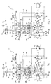
- Fig. 1 shows a first embodiment of the control according to the invention.
- the control 1 for controlling the slewing gear of an excavator designed.
- An adjustable hydraulic pump 2 is not connected to a drive shaft 50 shown drive motor, e.g. a diesel engine. About one through the Working lines 3 and 4 formed drive circuit is the hydraulic motor 5 with the Hydraulic pump 2 in connection. The hydraulic motor 5 drives the drive shaft 6 not shown slewing gear of the excavator.
- the pressure fluid of the drive circuit is replenished via a feed device 7 which a feed pump 8 also connected to the drive motor.
- the Feed pump 8 sucks continuously from a pressurized fluid tank 10 via a feed filter 9 Pressurized fluid and feeds this into the feed line 11.
- the feed line 11 is over Check valves 12 and 13 connected to the working lines 3 and 4 and feeds it Pressurized fluid in each case into the working line 3 or 4 carrying the low pressure.
- the Feed pressure is regulated by pressure regulating valves 14 and 15. To limit the Pressure in the feed line 11, the pressure relief valve 16.
- the displacement volume of the hydraulic pump 2 is controlled via the Manual control transmitter 17, with the pressure fluid tank 10 and the control pressure filter 18th communicates with a control pressure feed 19.
- the hand control transmitter 17 acts on one of the two control lines 20 depending on its deflection or 21 with a control pressure. Both are in the neutral position shown in FIG. 1 Control lines 20 and 21 via the hand control transmitter 17 to the pressurized fluid tank 10 ventilated.
- the control lines 20, 21 are via throttling points 22 and 23 and closer to Descriptive brake valves 24 and 25, each with a signal pressure chamber 26 and 27 of the Adjustment device 28 connected.
- An actuating piston 28a is arranged between the actuating pressure chambers 26 and 27 a piston rod 29 adjusts the displacement volume of the hydraulic pump 2.
- the Adjusting piston 28a is shown in FIG. 1 via centering springs 30 and 31 Centered neutral position.
- the suction device 32 consists of two Check valves 33 and 34 and serves to suck up pressure fluid from the Pressurized fluid tank 10 during the return of the actuating piston 28a to it Neutral.
- the brake valves 24 and 25 each have two control pressure chambers 35 and 36 and 37 and 38.
- the control pressure chambers 36 and 37 are connected via a shuttle valve 39 the two control lines 20 and 21 connected.
- the control pressure chambers 36 and 37 opposing drive pressure chambers 35 and 38 are via working line connection lines 40 and 41, each with one of the two working lines 3 or 4 connected.
- both control lines 20 and 21 via the hand control transmitter 17 to the pressurized fluid tank 10 so that the Control pressure chambers 36 and 37 are depressurized.
- the working lines 3 and 4 are also depressurized, so that between the Control pressure chambers 35 and 37 on the one hand and 36 and 38 on the other hand none Pressure difference.
- the brake valves 24 and 25 are therefore adjustable Compression springs 42 and 43 are held with their unthrottled switching positions 44 and 45.
- Throttling points 22 and 23 are adjustable in the exemplary embodiment via a transmitter 46 Pressure cut-off valve 47 provided that the pressure-carrying control line 20 or 21 at Limited to exceed a predetermined maximum pressure to the pressure fluid tank 10.
- Pressure cut-off valve 47 provided that the pressure-carrying control line 20 or 21 at Limited to exceed a predetermined maximum pressure to the pressure fluid tank 10.
- Another pressure relief valve 48 is via a shuttle valve 49 from the working lines 3 and 4 controlled.
- Fig. 2 shows the hydraulic control in the acceleration phase.
- the control line 20 via the Control pressure filter 18 supplied with control pressure from the control pressure feed 19, while the other control line 21 is vented to the pressurized fluid tank 10.
- the actuating pressure chamber 26 is supplied with control pressure via the brake valve 24 acted on, so that the actuating piston 28a in the indicated by the arrow 61 Shifts direction.
- the hydraulic pump 2 is swung out accordingly and in the Working line 4 built up a corresponding high pressure to the hydraulic motor 5 in the desired direction of rotation. In this way, the hydraulic motor 5 coupled slewing gear of the excavator accelerates.
- the brake valves 24 and 25 are located in the unthrottled switching positions 44 and 45, since during the in Fig. 2nd shown acceleration phase in the control line 20 and thus also in the Control pressure chambers 36 and 37 is a corresponding control pressure that the Brake valves 24 and 25 presses into their unthrottled switching positions.
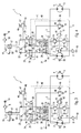
- the joystick 60 can be moved from the Operator are released so that this is shown in Fig. 3 Neutral position swings back. Then the control line 20 as well Control line 21 vented to the pressure fluid tank 10 and the control pressure in the Control line 20 removed. The control pressure spaces 36 and 37 also become corresponding the brake valves 24 and 25 are no longer subjected to control pressure.
- the switching position of the other brake valve 25 is without in this operating state Significance, since the pressure fluid flowing into the control pressure chamber 27 does not have the Brake valve 25, but via the suction device 32, i.e. about the open Check valve 33, is sucked from the pressurized fluid tank 10.
- the actuating piston 28a in contrast to the operating state shown in FIG returned to its neutral position shown in Figure 1. This requires a relatively quick Swinging back the hydraulic pump 2 to zero displacement, so that the Hydromotor 5 is no longer driven by this. This will make a uncontrolled swiveling of the slewing gear is effective in this operating state prevented.
- the hydraulic control according to the invention works on the same principle.
- the brake valve 25 Backflow of the pressure fluid from the one filled during the acceleration phase Signal pressure chamber 27 to the pressure fluid tank 10 in the deceleration phase as described above, while the switching position of the brake valve 24 then is meaningless.
- Fig. 5 shows a second embodiment of the control according to the invention in its Neutral.
- the controller 1 is for activation the slewing gear of an excavator. Elements already described are included matching reference numerals, so that there is a repetitive Description unnecessary.
- the brake valves 24 and 25 each have the embodiment shown in FIG. 5 a control pressure chamber 36 or 37.
- the drive pressure chambers 36 and 37 are connected to the two control lines 20 and 21 via a shuttle valve 39.
- the Control pressure chambers 36 and 37 opposite each other are a reset element in Form of a return spring 80 and 81 provided.
- Each of the two brake valves 24 and 25 is therefore determined by the difference in force between one of the control pressure in the larger control pressure acted upon control line 20 and 21 exerted actuating force and a restoring force exerted by the respective restoring spring 80 or 81.
- the two control lines 20 and 21 are in the neutral position shown in FIG. 5 via the hand control transmitter 17 to the pressurized fluid tank 10 so that the Control pressure chambers 36 and 37 are depressurized.
- the brake valves 24 and 25 are therefore by the return springs 80 and 81 in their respective throttled switching position 70 or 71 switched.
- FIG. 5 The function of the brake valves 24 and 25 according to the invention is shown in FIG the embodiment shown in Fig. 5 described in more detail.
- the hydraulic pump 2 is pivoted in one of its conveying directions. This will the control line 20 or the control stick 60 of the manual control transmitter 17 Control line 21 via the control pressure filter 18 from the control pressure feed 19 Control pressure is applied while the other control line to the pressurized fluid tank 10 is ventilated out. As a result, the signal pressure chamber 26 or Signal pressure chamber 27 via the brake valve 24 or the brake valve 25 with control pressure acted upon, so that the adjusting piston 28a moves accordingly.
- the hydraulic pump 2 is swung out accordingly and in one of the working lines 3 or 4 corresponding high pressure built up in order to the hydraulic motor, not shown in Fig.
- the brake valves 24 and 25 are in the unthrottled Switch positions 44 and 45, because during the acceleration phase in one of the two Control lines 20 or 21 and thus also in the control pressure chambers 36 and 37 corresponding control pressure is located, the brake valves 24 and 25 in their unthrottled switch positions 44 and 45 presses.
- the joystick 60 can be moved from the Operator are released so that it swings back into its neutral position.
- the control line 20 and the control line 21 then become the pressurized fluid tank 10 vented out and the control pressure in the control lines 20, 21 reduced.
- Corresponding the control pressure spaces 36 and 37 of the brake valves 24 and 25 are also no longer charged with control pressure.
- the hydraulic pump 2 is initially still in their swung out position.
- the pressure fluid escapes from during the Acceleration phase with pressure fluid acted upon by the control pressure chamber 26 or 27 the brake valve 24 or 25 assigned to the control pressure chamber and the manual control transmitter 17 to the pressure fluid tank 10.
- the two brake valves 24 and 25 are located here now in its throttled switching position 70 or 71, since this is from the assigned Return spring 80 and 81 are acted upon and the control pressure chambers 36 and 37 are essentially depressurized.
- the reflux of the pressure fluid from the respective Control pressure chamber 26 or 27 is therefore by the respectively assigned brake valve 24 or 25 throttled.
- the actuating piston 28 is therefore reset relatively slowly, which manifests itself in a sensitive, hesitant braking of the slewing gear.
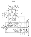
- the invention can also be used in conjunction with a pilot control use, as is known in principle from DE 44 05 472 A1.
- FIG. 6 shows a hydraulic control according to the invention with another, expedient embodiment for a pilot control. That illustrated in Fig. 6 third exemplary embodiment is designed similarly to the second illustrated in FIG. 5 Embodiment. Elements already described are the same Provide reference numerals, so that the following description relates only to the Differences and peculiarities.
- the feed device 7 is not used in the embodiment shown in FIG. 6 only to make up work cycle 2 to 4, but also to feed Pressure fluid to the adjusting device 28.
- Each brake valve 24 and 25 is one Pressure control valve 90, 91 assigned, which in each case upstream of the assigned Brake valve 24, 25 is arranged.
- the pressure control valves 90 and 91 are on the one hand the feed line 11 of the feed device 7 and on the other hand with the pressurized fluid tank 10 connected.
- Each pressure control valve 90, 91 is connected via a connecting line 92, 93 to the associated brake valve 24, 25 connected.
- the control of the pressure control valve 90 or 91 is proportional to the pressure difference between that in the respective Connection line 92 or 93 prevailing signal pressure and the control pressure in the assigned control line 20 or 21.
- one of the control inputs of the Pressure control valve 90 or 91 via an associated diversion line 94 or 95 with the Connection line 92 or 93 connected.
- a different control input of the Pressure control valve 90 or 91 is in with the associated control line 20 or 21 in Connection.
- the signal pressure prevailing in the connecting lines 92 and 93 is therefore essentially that prevailing in the assigned control line 20 or 21 Control pressure proportional.
- the compression springs 96 and 97 ensure that the Signal pressure slightly, e.g. 1 to 2 bar, above that in the assigned control line 20 or 21 prevailing control pressure.
- the pressure in the respective signal pressure chamber 26 or 27 prevailing signal pressure through the respective pressure control valve 90 or 91 in substantially proportional to that prevailing in the respective control line 20 or 21 Tax pressure measured.
- the pressure fluid flows out of the Signal pressure chamber 26 or 27 in the manner explained with reference to FIGS. 1 to 4 via the respective brake valve 24 or 25 via the respective pressure relief valve 90 or 91 back to the pressure fluid tank 10.
- the suction device 32 is not necessary in this embodiment, because the Pressurized fluid supply to the signal pressure chamber, the volume of which is at Reset in neutral position increased, via the feed device 7, the feed line 11 and the associated pressure control valve 90 or 91 and the associated brake valve 24 or 25 takes place.
- the advantage is in particular that there is no suction resistance is overcome, but via the feed pump 8 an active feed into the Adjustment device 28 takes place.
- a possible contamination by dirt particles is safely and effectively avoided by the feed filter 9.
- the invention is not limited to the illustrated embodiment.
- the brake valves 24 and 25 are not necessarily directly in the Control lines 20 and 21 to be arranged. You can anywhere in the Return line between the control pressure chambers 26 and 27 and the pressure fluid tank be provided.
Landscapes
- Engineering & Computer Science (AREA)
- General Engineering & Computer Science (AREA)
- Mining & Mineral Resources (AREA)
- Civil Engineering (AREA)
- Structural Engineering (AREA)
- Mechanical Engineering (AREA)
- Physics & Mathematics (AREA)
- Fluid Mechanics (AREA)
- Fluid-Pressure Circuits (AREA)
- Operation Control Of Excavators (AREA)
Abstract
Description
- Fig. 1
- ein erstes Ausführungsbeispiel der erfindungsgemäßen hydraulischen Steuerung in der Neutralstellung,
- Fig. 2
- das Ausführungsbeispiel entsprechend Figur 1 während der Beschleunigungsphase,
- Fig. 3
- das Ausführungsbeispiel entsprechend Figur 1 während der Verzögerungsphase, wenn das Drehwerk keinen Drehwiderstand erfährt,
- Fig. 4
- das Ausführungsbeispiel entsprechend Figur 1 während der Verzögerungsphase, wenn das Drehwerk einen Drehwiderstand erfährt,
- Fig. 5
- ein zweites Ausführungsbeispiel der erfindungsgemäßen hydraulischen Steuerung in der Neutralstellung, und
- Fig. 6
- ein drittes Ausführungsbeispiel der erfindungsgemäßen hydraulischen Steuerung in der Neutralstellung.
Claims (15)
- Hydraulische Steuerung, insbesondere zum Ansteuern des Drehwerks eines Baggers, mitdadurch gekennzeichnet, daß jeder Verbindung zwischen jeder der beiden Stelldruckkammern (26; 27) mit dem Druckfluid-Tank (10) jeweils ein separates Bremsventil (24; 25) zugeordnet ist,einem hydraulischen Antriebskreislauf (2 - 4) mit einer Hydropumpe (2) und einem Hydromotor, sowie einer ersten und einer zweiten die Hydropumpe (2) mit dem Hydromotor verbindenden Arbeitsleitung (3, 4),einer Verstellvorrichtung (28) zum Verstellen eines zwischen zwei Stelldruckkammern (26, 27) angeordneten, auf das Verdrängungsvolumen der Hydropumpe (2) einwirkenden Stellkolbens (28a) in Abhängigkeit von der Druckdifferenz zwischen zwei Steuerleitungen (20, 21) undzumindest einem Bremsventil, das bei verschwindendem Steuerdruck in den Steuerleitungen (20, 21) den Rückfluß des Druckfluids aus den Stelldruckkammern (26, 27) in den Druckfluid-Tank (10) drosselt,
wobei jedes der beiden Bremsventile (24; 25) durch eine Kraftdifferenz zwischen einer von dem Steuerdruck in der mit größerem Steuerdruck beaufschlagten Steuerleitung (20, 21) ausgeübten Stellkraft und einer von einem für jedes Bremsventil (24; 25) vorgesehenen Rückstellglied (80; 81) ausgeübten Rückstellkraft angesteuert wird. - Hydraulische Steuerung nach Anspruch 1,
dadurch gekennzeichnet,daß jedes Bremsventil (24; 25) als Schaltventil mit einer ersten Schaltstellung (44; 45) mit ungedrosseltem Durchfluß und einer zweiten Schaltstellung (70; 71) mit gedrosseltem Durchfluß ausgebildet ist,wobei sich jedes Bremsventil (24; 25) in der ersten Schaltstellung (44; 45) befindet, wenn die Kraftdifferenz zwischen der Stellkraft und der Rückstellkraft größer als ein vorgegebener Schwellwert ist undsich jedes Bremsventil (24; 25) in der zweiten Schaltstellung (70; 71) befindet, wenn die Kraftdifferenz zwischen der Stellkraft und dere Rückstellkraft kleiner als der vorgegebene Schwellwert ist. - Hydraulische Steuerung nach Anspruch 1 oder 2,
dadurch gekennzeichnet, daß jedes Bremsventil (24; 25) jeweils eine Ansteuer-Druckkammer (36; 37) aufweist, die mit den Steuerleitungen (20, 21) verbunden ist. - Hydraulische Steuerung nach Anspruch 3,
dadurch gekennzeichnet, daß die Ansteuer-Druckkammern (36; 37) der Bremsventile (24; 25) über ein Wechselventil (39) mit den Steuerleitungen (20, 21) verbunden sind. - Hydraulische Steuerung nach einem der Ansprüche 1 bis 4,
dadurch gekennzeichnet, daß die Rückstellglieder als Rückstellfedern (80, 81) ausgebildet sind: - Hydraulische Steuerung, insbesondere zum Ansteuern des Drehwerks eines Baggers, mitdadurch gekennzeichnet,einem hydraulischen Antriebskreislauf (2-4) mit einer Hydropumpe (2) und einem Hydromotor (5), sowie einer ersten und einer zweiten die Hydropumpe (2) mit dem Hydromotor (5) verbindenden Arbeitsleitung (3, 4),einer Verstellvorrichtung (28) zum Verstellen eines zwischen zwei Stelldruckkammern (26, 27) angeordneten, auf das Verdrängungsvolumen der Hydropumpe (2) einwirkenden Stellkolbens (28a) in Abhängigkeit von der Druckdifferenz zwischen zwei Steuerleitungen (20, 21) undzumindest einem Bremsventil, das bei verschwindendem Steuerdruck in den Steuerleitungen (20, 21) den Rückfluß des Druckfluids aus den Stelldruckkammern (26, 27) in den Druckfluid-Tank (10) drosselt,daß jeder Verbindung zwischen jeder der beiden Stelldruckkammern (26; 27) mit dem Druckfluid-Tank (10) jeweils ein separates Bremsventil (24; 25) zugeordnet ist,wobei ein erstes der beiden Bremsventile (24) durch die Druckdifferenz zwischen dem Arbeitsdruck in der ersten Arbeitsleitung (3) und dem Steuerdruck in der mit größerem Druck beaufschlagten Steuerleitung (20, 21) angesteuert wird unddas zweite der beiden Bremsventile (25) durch die Druckdifferenz zwischen dem Arbeitsdruck in der zweiten Arbeitsleitung (4) und dem Steuerdruck in der mit größerem Druck beaufschlagten Steuerleitung (20, 21) angesteuert wird.
- Hydraulische Steuerung nach Anspruch 6,
dadurch gekennzeichnet, daß jedes Bremsventil (24; 25) jeweils mit derjenigen Arbeitsleitung (3; 4) verbunden ist, die beim Ausschwenken der Hydropumpe (2) durch Beaufschlagen der dem Bremsventil (24; 25) zugeordneten Stelldruckkammer (26; 27) die Niederdruck-Rücklaufleitung (3; 4) des Antriebskreislaufes (3, 4) bildet. - Hydraulische Steuerung nach Anspruch 6 oder 7,
dadurch gekennzeichnet,daß jedes Bremsventil (24; 25) als Schaltventil mit einer ersten Schaltstellung (44; 45) mit ungedrosseltem Durchfluß und einer zweiten Schaltstellung (70; 71) mit gedrosseltem Durchfluß ausgebildet ist,wobei sich das Bremsventil (24; 25) in der ersten Schaltstellung (44; 45) befindet, wenn die Druckdifferenz zwischen dem Arbeitsdruck in der zugeordneten Arbeitsleitung (3; 4) und dem Steuerdruck in der mit größerem Druck beaufschlagten Steuerleitung (20, 21) kleinere als ein vorgegebener Schwellwert ist undsich das Bremsventil (24; 25) in der zweiten Schaltstellung (70; 71) befindet, wenn die Druckdifferenz zwischen dem Arbeitsdruck in der zugeordneten Arbeitsleitung (3; 4) und dem Steuerdruck in der mit größerem Druck beaufschlagten Steuerleitung (20, 21) größer als der vorgegebene Schwellwert ist. - Hydraulische Steuerung nach einem der Ansprüche 6 bis 8,
dadurch gekennzeichnet, daß jedes Bremsventil (24; 25) zwei Ansteuer-Druckkammern (35, 36; 37, 38) aufweist,
wobei eine erste Ansteuer-Druckkammer (35; 38) mit der zugeordneten Arbeitsleitung (3; 4) und die zweite Ansteuer-Druckkammer (36; 37) mit den Steuereleitungen (20, 21) verbunden ist. - Hydraulische Steuerung nach Anspruch 9,
dadurch gekennzeichnet, daß die zweiten Ansteuer-Druckkammern (36, 37) über ein Wechselventil (39) mi den Steuerleitungen (20, 21) verbunden sind. - Hydraulische Steuerung nach einem der Ansprüche 1 bis 10,
dadurch gekennzeichnet, daß die Bremsventile (24, 25) in den Steuerleitungen (20, 21) angeordnet sind. - Hydraulische Steuerung nach Anspruch 11,
dadurch gekennzeichnet, daß zwischen den Bremsventilen (24; 25) und den zugeordneten Stelldruckkammern (26, 27) eine Nachsaugeeinrichtung (32) zum Nachsaugen von Druckfluid aus dem Druckfluid-Tank (10) vorgesehen ist. - Hydraulische Steuerung nach einem der Ansprüche 1 bis 12,
dadurch gekennzeichnet, daß die Steuerleitungen (20, 21) über einen mit dem Druckfluid-Tank (10) und einer Steuerdruckeinspeisung (19) verbundenen Steuergeber (17) wechselseitig mit Steuerdruck beaufschlagbar oder zum Druckfluid-Tank (10) hin belüftbar sind. - Hydraulische Steuerung nach einem dere Ansprüche 1 bis 13,
dadurch gekennzeichnet, daß ein Druckabschneideventil (47) zur Begrenzung des Steuerdrucks in den Steuerleitungen (20, 21) auf einen Maximaldruck vorgesehen ist. - Hydraulische Steuerung nach einem der Ansprüche 1 bis 14,
dadurch gekennzeichnet,daß eine Speiseeinrichtung (7) zum Einspeisen von Druckfluid in den Arbeitskreislauf (2-4) vorgesehen ist,daß jedem Bremsventil (24; 25) jeweils ein Druckregelventil (90; 91) zugeordnet ist und daß der dem jeweiligen Bremsventil (24; 25) zugeordneten Stelldruckkammer (26, 27) über das jeweilige Bremsventil (24; 25) ein Stelldruck zuführbar ist, der von dem zugeordneten Druckregelventil (90; 91) in Abhängigkeit von dem in einer zugeordneten Steuerleitung (20; 21) herrschenden Steuerdruck geregelt wird.
Applications Claiming Priority (5)
| Application Number | Priority Date | Filing Date | Title |
|---|---|---|---|
| DE1996120664 DE19620664C1 (de) | 1996-05-22 | 1996-05-22 | Hydraulische Steuerung, insbesondere zum Ansteuern des Drehwerks eines Baggers |
| DE19620664 | 1996-05-22 | ||
| DE19625393 | 1996-06-25 | ||
| DE19625393A DE19625393A1 (de) | 1996-05-22 | 1996-06-25 | Drehwerksteuerung mit doppelseitiger Bremsung |
| PCT/EP1997/002570 WO1997044536A1 (de) | 1996-05-22 | 1997-05-20 | Drehwerksteuerung mit doppelseitiger bremsung |
Publications (3)
| Publication Number | Publication Date |
|---|---|
| EP0904468A1 EP0904468A1 (de) | 1999-03-31 |
| EP0904468B1 true EP0904468B1 (de) | 2002-03-13 |
| EP0904468B2 EP0904468B2 (de) | 2007-03-14 |
Family
ID=26025936
Family Applications (1)
| Application Number | Title | Priority Date | Filing Date |
|---|---|---|---|
| EP97923950A Expired - Lifetime EP0904468B2 (de) | 1996-05-22 | 1997-05-20 | Drehwerksteuerung mit doppelseitiger bremsung |
Country Status (5)
| Country | Link |
|---|---|
| US (1) | US6082107A (de) |
| EP (1) | EP0904468B2 (de) |
| JP (1) | JP3446834B2 (de) |
| DE (2) | DE19625393A1 (de) |
| WO (1) | WO1997044536A1 (de) |
Families Citing this family (14)
| Publication number | Priority date | Publication date | Assignee | Title |
|---|---|---|---|---|
| DE19735111C2 (de) * | 1997-08-13 | 1999-06-02 | Brueninghaus Hydromatik Gmbh | Drehwerksteuerung mit Brems- und Steuerventilen |
| DE19833489A1 (de) * | 1998-07-24 | 2000-01-27 | Mannesmann Rexroth Ag | Hydraulische Schaltung |
| DE10000110B4 (de) * | 2000-01-04 | 2004-06-24 | Sauer-Sundstrand Gmbh & Co. | Hydrostatischer Fahrzeugantrieb mit Steuerungseinrichtung und Steuerungseinrichtung für hydrostatische Antriebe |
| US6644335B2 (en) * | 2000-12-15 | 2003-11-11 | Caterpillar S.A.R.L. | Precision orificing for pilot operated control valves |
| EP1225281B1 (de) * | 2001-01-23 | 2008-01-16 | Brueninghaus Hydromatik Gmbh | Hydraulische Steuerung, insbesondere zum Ansteuern des Drehwerks eines Baggers |
| US7165396B2 (en) * | 2003-07-11 | 2007-01-23 | Eaton Corporation | Pump control override for tandem pumps |
| DE10343016B4 (de) * | 2003-09-17 | 2010-08-26 | Brueninghaus Hydromatik Gmbh | Hydraulisches Steuer- und Stellsystem mit Volumenausgleich |
| US6964163B2 (en) * | 2003-11-10 | 2005-11-15 | Sauer-Danfoss, Inc. | Dual check-relief valve |
| US7726125B2 (en) * | 2007-07-31 | 2010-06-01 | Caterpillar Inc. | Hydraulic circuit for rapid bucket shake out |
| DE102007056991B4 (de) * | 2007-11-27 | 2014-05-08 | Sauer-Danfoss Gmbh & Co. Ohg | Hydraulische Schaltungsanordnung mit einer Einrichtung zur Nullhubdruckregelung und Verfahren zur Druckregelung im Nullhubbetrieb |
| DE102011015286A1 (de) * | 2011-03-28 | 2012-10-04 | Liebherr-Werk Nenzing Gmbh | Hydraulische Bremsvorrichtung für einen Kranantreib sowie Kran |
| US10794480B2 (en) * | 2014-08-07 | 2020-10-06 | Kanzaki Kokyukoki Mfg. Co., Ltd. | Control mechanism for stepless transmission |
| DE102016002613B4 (de) * | 2016-03-03 | 2022-09-29 | Liebherr-Werk Ehingen Gmbh | Hydrauliksteuerkreis für ein Krandrehwerk |
| US10662980B2 (en) | 2017-10-03 | 2020-05-26 | Kubota Corporation | Hydraulic system in work machine |
Citations (1)
| Publication number | Priority date | Publication date | Assignee | Title |
|---|---|---|---|---|
| DE4116649A1 (de) * | 1991-05-22 | 1992-11-26 | Linde Ag | Verstellbare hydrostatische maschine |
Family Cites Families (9)
| Publication number | Priority date | Publication date | Assignee | Title |
|---|---|---|---|---|
| US3921503A (en) | 1972-03-21 | 1975-11-25 | Philip A Kubik | Control system for a fluid system |
| US4571941A (en) * | 1980-12-27 | 1986-02-25 | Hitachi Construction Machinery Co, Ltd. | Hydraulic power system |
| JPS57184749A (en) * | 1981-05-01 | 1982-11-13 | Hitachi Constr Mach Co Ltd | Control device for hydraulic system |
| JPS57184748A (en) * | 1981-05-01 | 1982-11-13 | Hitachi Constr Mach Co Ltd | Apparatus for controlling hydraulic system |
| US4554991A (en) * | 1984-02-23 | 1985-11-26 | Mud Hog Corporation | Auxiliary hydraulic drive system for road graders and the like |
| JPH0663264B2 (ja) * | 1984-07-20 | 1994-08-22 | 株式会社小松製作所 | 旋回式建設機械の旋回エネルギ回収再利用装置 |
| JPH02195074A (ja) * | 1989-01-23 | 1990-08-01 | Kubota Ltd | 車輌の油圧構造 |
| DE4231637C2 (de) * | 1992-09-22 | 1995-10-12 | Orenstein & Koppel Ag | Bremseinrichtung für einen über einen Antrieb bewegbaren Teil |
| DE4405472A1 (de) * | 1994-02-11 | 1995-08-17 | Caterpillar Inc | Hydraulische Steuerung |
-
1996
- 1996-06-25 DE DE19625393A patent/DE19625393A1/de not_active Ceased
-
1997
- 1997-05-20 EP EP97923950A patent/EP0904468B2/de not_active Expired - Lifetime
- 1997-05-20 US US09/142,931 patent/US6082107A/en not_active Expired - Fee Related
- 1997-05-20 JP JP54154097A patent/JP3446834B2/ja not_active Expired - Fee Related
- 1997-05-20 DE DE59706613T patent/DE59706613D1/de not_active Expired - Fee Related
- 1997-05-20 WO PCT/EP1997/002570 patent/WO1997044536A1/de not_active Ceased
Patent Citations (1)
| Publication number | Priority date | Publication date | Assignee | Title |
|---|---|---|---|---|
| DE4116649A1 (de) * | 1991-05-22 | 1992-11-26 | Linde Ag | Verstellbare hydrostatische maschine |
Non-Patent Citations (1)
| Title |
|---|
| W. Nimbler "Schwerpunkte der Hydrostatik in Baumaschinen", Sonderdruck aus VDBUM-Information, 1982. * |
Also Published As
| Publication number | Publication date |
|---|---|
| WO1997044536A1 (de) | 1997-11-27 |
| DE59706613D1 (de) | 2002-04-18 |
| US6082107A (en) | 2000-07-04 |
| EP0904468B2 (de) | 2007-03-14 |
| DE19625393A1 (de) | 1998-01-02 |
| JP3446834B2 (ja) | 2003-09-16 |
| EP0904468A1 (de) | 1999-03-31 |
| JP2000510935A (ja) | 2000-08-22 |
Similar Documents
| Publication | Publication Date | Title |
|---|---|---|
| EP0137184B1 (de) | Hydrauliksystem mit einer Pumpe mit unveränderlicher Fördermenge | |
| EP0904468B1 (de) | Drehwerksteuerung mit doppelseitiger bremsung | |
| DE19934782C2 (de) | Verfahren und Anordnung zum Steuern eines hydraulischen Fahrzeugantriebs | |
| DE3934641C2 (de) | ||
| EP0826110B1 (de) | Verschiebbare hydraulische leistungs- bzw. momentenregeleinrichtung | |
| DE3048186A1 (de) | Vorrichtung zur begrenzung des knickwinkels insbesondere fuer strassen-gelenkzuege | |
| EP0137185A2 (de) | Hydrauliksystem mit einer Pumpe mit variabler Fördermenge und einem Vorrangventil | |
| EP0144788B1 (de) | Leistungs-Regelvorrichtung für einen hydrostatischen Antrieb mit Fördermengeneinstellung | |
| EP0137186B1 (de) | Hydrauliksystem mit einer Pumpe mit unveränderlicher Fördermenge und einem Vorrangventil | |
| DE2528094A1 (de) | Steuersystem fuer hydrostatische getriebe | |
| EP0904467B1 (de) | Drehwerksteuerung mit speiseeinrichtung | |
| EP0141074B1 (de) | Hydrauliksystem mit einer Pumpe, einem Ventil, einer Zuführleitung und einer Signalleitung | |
| DE19850162C1 (de) | Hydrostatisches Getriebe | |
| DE4420704C2 (de) | Hydrostatischer Antrieb, insbesondere für das Drehwerk eines Baggers | |
| DE19620664C1 (de) | Hydraulische Steuerung, insbesondere zum Ansteuern des Drehwerks eines Baggers | |
| DE1630105C3 (de) | Hydrostatisches Getriebe für Kraftfahrzeuge | |
| EP1003972A1 (de) | Drehwerksteuerung mit brems- und steuerventilen | |
| DE2532768B2 (de) | Hydraulische Servomotoranlage | |
| DE3817313C2 (de) | ||
| DE4231637C2 (de) | Bremseinrichtung für einen über einen Antrieb bewegbaren Teil | |
| DE1775590C3 (de) | Hydrostatisches Getriebe mit einer SteUpumpe und einem Hydromotor | |
| DE10220376B4 (de) | Hydraulische Steuerung mit aktiver Rückstellung | |
| DE3001681A1 (de) | Steuereinrichtung fuer ein hydrostatisches getriebe | |
| DE1926301B2 (de) | Hydrostatisches getriebe | |
| DE2102142B2 (de) | Blockiergeschützte Fahrzeugbremsanlage |
Legal Events
| Date | Code | Title | Description |
|---|---|---|---|
| PUAI | Public reference made under article 153(3) epc to a published international application that has entered the european phase |
Free format text: ORIGINAL CODE: 0009012 |
|
| 17P | Request for examination filed |
Effective date: 19980717 |
|
| AK | Designated contracting states |
Kind code of ref document: A1 Designated state(s): DE FR GB IT SE |
|
| GRAG | Despatch of communication of intention to grant |
Free format text: ORIGINAL CODE: EPIDOS AGRA |
|
| GRAG | Despatch of communication of intention to grant |
Free format text: ORIGINAL CODE: EPIDOS AGRA |
|
| GRAH | Despatch of communication of intention to grant a patent |
Free format text: ORIGINAL CODE: EPIDOS IGRA |
|
| 17Q | First examination report despatched |
Effective date: 20010711 |
|
| GRAH | Despatch of communication of intention to grant a patent |
Free format text: ORIGINAL CODE: EPIDOS IGRA |
|
| REG | Reference to a national code |
Ref country code: GB Ref legal event code: IF02 |
|
| GRAA | (expected) grant |
Free format text: ORIGINAL CODE: 0009210 |
|
| AK | Designated contracting states |
Kind code of ref document: B1 Designated state(s): DE FR GB IT SE |
|
| REF | Corresponds to: |
Ref document number: 59706613 Country of ref document: DE Date of ref document: 20020418 |
|
| GBT | Gb: translation of ep patent filed (gb section 77(6)(a)/1977) |
Effective date: 20020617 |
|
| ET | Fr: translation filed | ||
| PLBI | Opposition filed |
Free format text: ORIGINAL CODE: 0009260 |
|
| PLBF | Reply of patent proprietor to notice(s) of opposition |
Free format text: ORIGINAL CODE: EPIDOS OBSO |
|
| 26 | Opposition filed |
Opponent name: LINDE AKTIENGESELLSCHAFT, WIESBADEN Effective date: 20021211 |
|
| PLBF | Reply of patent proprietor to notice(s) of opposition |
Free format text: ORIGINAL CODE: EPIDOS OBSO |
|
| APBP | Date of receipt of notice of appeal recorded |
Free format text: ORIGINAL CODE: EPIDOSNNOA2O |
|
| PLBQ | Unpublished change to opponent data |
Free format text: ORIGINAL CODE: EPIDOS OPPO |
|
| PLAB | Opposition data, opponent's data or that of the opponent's representative modified |
Free format text: ORIGINAL CODE: 0009299OPPO |
|
| R26 | Opposition filed (corrected) |
Opponent name: LINDE AKTIENGESELLSCHAFT, WIESBADEN Effective date: 20021211 |
|
| APBQ | Date of receipt of statement of grounds of appeal recorded |
Free format text: ORIGINAL CODE: EPIDOSNNOA3O |
|
| APAA | Appeal reference recorded |
Free format text: ORIGINAL CODE: EPIDOS REFN |
|
| APAH | Appeal reference modified |
Free format text: ORIGINAL CODE: EPIDOSCREFNO |
|
| APBU | Appeal procedure closed |
Free format text: ORIGINAL CODE: EPIDOSNNOA9O |
|
| PUAH | Patent maintained in amended form |
Free format text: ORIGINAL CODE: 0009272 |
|
| STAA | Information on the status of an ep patent application or granted ep patent |
Free format text: STATUS: PATENT MAINTAINED AS AMENDED |
|
| 27A | Patent maintained in amended form |
Effective date: 20070314 |
|
| AK | Designated contracting states |
Kind code of ref document: B2 Designated state(s): DE FR GB IT SE |
|
| GBTA | Gb: translation of amended ep patent filed (gb section 77(6)(b)/1977) |
Effective date: 20070411 |
|
| PGFP | Annual fee paid to national office [announced via postgrant information from national office to epo] |
Ref country code: SE Payment date: 20070515 Year of fee payment: 11 |
|
| PGFP | Annual fee paid to national office [announced via postgrant information from national office to epo] |
Ref country code: DE Payment date: 20070522 Year of fee payment: 11 |
|
| REG | Reference to a national code |
Ref country code: SE Ref legal event code: RPEO |
|
| ET3 | Fr: translation filed ** decision concerning opposition | ||
| PGFP | Annual fee paid to national office [announced via postgrant information from national office to epo] |
Ref country code: GB Payment date: 20070522 Year of fee payment: 11 |
|
| PGFP | Annual fee paid to national office [announced via postgrant information from national office to epo] |
Ref country code: IT Payment date: 20070524 Year of fee payment: 11 |
|
| PGFP | Annual fee paid to national office [announced via postgrant information from national office to epo] |
Ref country code: FR Payment date: 20070516 Year of fee payment: 11 |
|
| GBPC | Gb: european patent ceased through non-payment of renewal fee |
Effective date: 20080520 |
|
| REG | Reference to a national code |
Ref country code: FR Ref legal event code: ST Effective date: 20090119 |
|
| PG25 | Lapsed in a contracting state [announced via postgrant information from national office to epo] |
Ref country code: FR Free format text: LAPSE BECAUSE OF NON-PAYMENT OF DUE FEES Effective date: 20080602 Ref country code: DE Free format text: LAPSE BECAUSE OF NON-PAYMENT OF DUE FEES Effective date: 20081202 |
|
| PG25 | Lapsed in a contracting state [announced via postgrant information from national office to epo] |
Ref country code: GB Free format text: LAPSE BECAUSE OF NON-PAYMENT OF DUE FEES Effective date: 20080520 |
|
| PG25 | Lapsed in a contracting state [announced via postgrant information from national office to epo] |
Ref country code: IT Free format text: LAPSE BECAUSE OF NON-PAYMENT OF DUE FEES Effective date: 20080520 |
|
| PG25 | Lapsed in a contracting state [announced via postgrant information from national office to epo] |
Ref country code: SE Free format text: LAPSE BECAUSE OF NON-PAYMENT OF DUE FEES Effective date: 20080521 |