EP0903970B1 - Gehäuse mit Klemmen und Klemmbedeckungen - Google Patents
Gehäuse mit Klemmen und Klemmbedeckungen Download PDFInfo
- Publication number
- EP0903970B1 EP0903970B1 EP98306851A EP98306851A EP0903970B1 EP 0903970 B1 EP0903970 B1 EP 0903970B1 EP 98306851 A EP98306851 A EP 98306851A EP 98306851 A EP98306851 A EP 98306851A EP 0903970 B1 EP0903970 B1 EP 0903970B1
- Authority
- EP
- European Patent Office
- Prior art keywords
- piece
- enclosure
- stand
- opening
- stands
- Prior art date
- Legal status (The legal status is an assumption and is not a legal conclusion. Google has not performed a legal analysis and makes no representation as to the accuracy of the status listed.)
- Expired - Lifetime
Links
- 230000014759 maintenance of location Effects 0.000 description 6
- 238000004519 manufacturing process Methods 0.000 description 3
- 239000004033 plastic Substances 0.000 description 3
- 239000002184 metal Substances 0.000 description 2
- 238000012986 modification Methods 0.000 description 2
- 230000004048 modification Effects 0.000 description 2
- 230000035939 shock Effects 0.000 description 2
- 239000002537 cosmetic Substances 0.000 description 1
- 229920001971 elastomer Polymers 0.000 description 1
- 239000000806 elastomer Substances 0.000 description 1
- 238000002347 injection Methods 0.000 description 1
- 239000007924 injection Substances 0.000 description 1
- 230000002093 peripheral effect Effects 0.000 description 1
- 229910001220 stainless steel Inorganic materials 0.000 description 1
- 239000010935 stainless steel Substances 0.000 description 1
- 238000005728 strengthening Methods 0.000 description 1
- 229920002725 thermoplastic elastomer Polymers 0.000 description 1
- 238000013024 troubleshooting Methods 0.000 description 1
Images


Classifications
-
- H—ELECTRICITY
- H05—ELECTRIC TECHNIQUES NOT OTHERWISE PROVIDED FOR
- H05K—PRINTED CIRCUITS; CASINGS OR CONSTRUCTIONAL DETAILS OF ELECTRIC APPARATUS; MANUFACTURE OF ASSEMBLAGES OF ELECTRICAL COMPONENTS
- H05K5/00—Casings, cabinets or drawers for electric apparatus
- H05K5/10—Casings, cabinets or drawers for electric apparatus comprising several parts forming a closed casing
- H05K5/15—Casings, cabinets or drawers for electric apparatus comprising several parts forming a closed casing assembled by resilient members
Definitions
- This invention relates generally to enclosures used to house-electronic instruments and the like and more specifically to an enclosure with two pieces clamped together.
- Screws are commonly used to join the two enclosure pieces.
- screws typically require metal inserts which in turn require an additional manufacturing step.
- screws are relatively time consuming and require relatively expensive equipment.
- Plastic molded parts may also be designed to be snapped together.
- Features may be molded into one part that snap into corresponding features molded into another part.
- Snap fit parts are typically easy to assemble.
- the features may require substantially increased complexity in the plastic molds, requiring tighter tolerances and additional time to tune the molds to ensure that the parts are held precisely and securely.
- snap together parts may be difficult to disassemble for troubleshooting or changes after assembly, possibly requiring a tool or fixture to disengage multiple snap features.
- the invention provides an enclosure as defined in claim 1.
- a two piece enclosure uses molded features for hinge action retention on one side and spring clips on an opposite side.
- the exclosure includes snap-on stands that serve as anti-slip feet to permit the enclosure to stand in a vertical orientation.
- the stands cover the spring clips.
- the spring clips provide a retention force that is substantially higher than the retention force provided by snap together parts. The parts are low cost and easy to remove. Most important, the combination of spring clips and snap-on stands facilitate automatic manufacturing, enabling the enclosure to simply be pressed against the clips and stands.
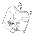
- Figure 1 is a perspective view of the bottom, right, and rear surfaces of an enclosure with a spring clip and stand in accordance with an example embodiment of the invention.
- Figure 2 is a plane front (or rear) view of a stand with a spring clip inserted.
- Figure 3 is a top view of a stand with a spring clip inserted.
- Figure 4 is a perspective view of a stand.
- Figure 5 is a perspective view of the bottom rear corner of the right enclosure piece showing an opening for receiving the spring clip and stand.
- Figure 6 is a perspective view of the inside surface of the bottom front corner of the left enclosure piece illustrating a spring clip and a stand snapped into a corresponding opening.
- Figure 7 is a perspective front and bottom view of the left part of the enclosure illustrating hinge details in the inside top surface.
- Figure 8 is a perspective rear and bottom view of the right part of the enclosure illustrating hinge details in the inside top surface.
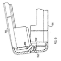
- Figure 9 is a cross section view illustrating how the 2 enclosure parts are hinged together.
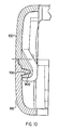
- Figure 10 is an expanded cross section view of the hinges as in figure 9 with the 2 enclosure parts fitted together.
- FIG. 1 illustrates an example embodiment of the invention.
- An enclosure has two major pieces, 100 and 102. Each enclosure piece has an opening 104 at two corners.
- Two metal spring clips 106 snap into the openings 104 to provide a high retention force for holding the pieces together.
- Two flexible stands 108 also snap into the openings 104, providing a cosmetic cover for the spring clips 106 as well as providing anti-slip feet to support the completed enclosure in a vertical orientation as illustrated in figure 1.
- one spring clip 106 is placed into each stand 108 and the two enclosure pieces (100 and 102) are simply pressed onto the spring clips and stands so that both spring clips and both stands snap into the openings 104 in the enclosure pieces.
- the spring clips 106 are fabricated from half-hard stainless steel.
- each stand 108 is injection molded using a thermoplastic elastomer (Sanoprene) from Advanced Elastomer Systems.
- Figure 1 illustrates the bottom, rear, and right side of the enclosure. Right and left are defined as viewed from the front side, which faces away in figure 1.
- the bottom is the side receiving the spring clips. Therefore, side 100 is the right side and side 102 is the left side.
- FIG 2 illustrates a view of one stand 108 along its longest dimension, with a spring clip 106 inserted into the stand.
- Figure 3 illustrates a top view of a stand 108, with a spring clip 106 inserted into the stand.
- Figure 4 illustrates a perspective view of a stand 108 without a spring clip.
- Each stand 108 has two retainer sections 200 and 202 on each end that provide retention of the stand to the enclosure.
- Figure 5 is an expanded external view of an opening 104 for receiving a stand and spring clip.
- a larger portion 502 of the opening 104 receives retainer section 202 (figures 2-4) of a stand.
- Figure 6 is an internal view of an opening with a stand and spring clip inserted.
- retainer section 200 inserts into slot 500 of the opening 104 and retainer section 202 and the spring clip 106 both insert into portion 502 of the opening 104.
- FIG. 7 is a view of the inside of the left side 102 of the enclosure, illustrating three wedge shaped hinge sections 700 along the inside surface of the top side.
- each hinge section 700 is about 6.4 mm long.
- the number and length of each hinge section may vary to accommodate various strengthening ribs, vent holes, or industrial design details.
- FIG 8 is a view of the inside of the right side 100 of the enclosure, illustrating three hinge sections 800 along the inside surface of the top side.
- Each hinge section 800 has a wedge shaped pocket (not visible in figure 8) for receiving a hinge section 700 (figure 7) from the left side of the enclosure.
- Figure 9 is front view of the right side 100 of the enclosure and the left side 102 of the enclosure with part of the top side cut away to illustrate a cross section through the hinges.
- Wedge shaped hinge section 700 on the left side 102 inserts into wedge shaped pocket 900 on the right side 100.
- the matching edges on the top side are brought together as illustrated in figure 9 to mate the hinge sections and then the matching edges of the bottom side are brought together.
- Figure 10 is an expanded view of the hinge parts further illustrating the wedge shaped hinge section 700 on the left side 102 and the wedge shaped pocket 900 on the right side 100.
- the combination of hinge and spring clips provides ease of automated assembly, ease of disassembly, low tooling cost, low part cost, pleasing aesthetics, and a capability to withstand rigorous vibration and mechanical shock.
- the example embodiment has been illustrated with two clips and two stands.
- a single clip and stand may be appropriate for some enclosure designs or more than two clips and stands may be appropriate.
- the example embodiment has been illustrated with a combination of hinge action and spring clips. In some enclosure designs, it may be appropriate to use only spring clips.
- the example embodiment has been illustrated with two stands for vertical operation. Additional feet may be added for optional horizontal or vertical operation.
Landscapes
- Engineering & Computer Science (AREA)
- Microelectronics & Electronic Packaging (AREA)
- Clamps And Clips (AREA)
- Casings For Electric Apparatus (AREA)
- Closures For Containers (AREA)
Claims (2)
- Eine Umhüllung, die folgende Merkmale aufweist:ein erstes Stück (100), wobei das erste Stück zumindest eine Öffnung (104) aufweist;ein zweites Stück (102), wobei das zweite Stück zumindest eine Öffnung aufweist;eine Federklemme (106), die einen ersten und einen zweiten gebogenen Abschnitt aufweist, so daß eine Federkraft der Bewegung der gebogenen Abschnitte weg voneinander widersteht, wobei der erste gebogene Abschnitt in die Öffnung des ersten Stücks eingeschnappt ist und der zweite gebogene Abschnitt in die Öffnung des zweiten Stücks eingeschnappt ist, um die zwei Stücke zu verbinden; und gekennzeichnet durcheinen Ständer (108), wobei der Ständer ein erstes und ein zweites Ende aufweist, wobei das erste Ende in die Öffnung des ersten Stücks geschnappt ist und das zweite Ende in die Öffnung des zweiten Stücks geschnappt ist, wobei der Ständer die Federklemme abdeckt.
- Die Umhüllung gemäß Anspruch 1, die ferner folgende Merkmale aufweist:eine erste Oberfläche auf dem ersten Stück, wobei die Öffnung für das erste Stück in der ersten Oberfläche vorliegt;eine zweite Oberfläche auf dem ersten Stück, die parallel zu der ersten Oberfläche ist;eine Tasche (800) auf der zweiten Oberfläche;eine dritte Oberfläche auf dem zweiten Stück, wobei die Öffnung für das zweite Stück in der dritten Oberfläche vorliegt;eine vierte Oberfläche auf dem zweiten Stück, die parallel zu der dritten Oberfläche ist;einen Vorstand (700) auf der vierten Oberfläche, der so positioniert ist, daß wenn das erste Stück mit dem zweiten Stück verbunden ist, der Vorstand in die Tasche eingefügt ist, wodurch ein Gelenk gebildet wird, das die zweite und die vierte Oberfläche zusammenhält und der zweiten Oberfläche ermöglicht, sich relativ zu der vierten Oberfläche um das Gelenk zu drehen.
Applications Claiming Priority (2)
| Application Number | Priority Date | Filing Date | Title |
|---|---|---|---|
| US935952 | 1997-09-23 | ||
| US08/935,952 US5921422A (en) | 1997-09-23 | 1997-09-23 | Enclosure with spring clamps and stands covering the clamps |
Publications (3)
| Publication Number | Publication Date |
|---|---|
| EP0903970A2 EP0903970A2 (de) | 1999-03-24 |
| EP0903970A3 EP0903970A3 (de) | 2000-02-23 |
| EP0903970B1 true EP0903970B1 (de) | 2003-10-29 |
Family
ID=25467958
Family Applications (1)
| Application Number | Title | Priority Date | Filing Date |
|---|---|---|---|
| EP98306851A Expired - Lifetime EP0903970B1 (de) | 1997-09-23 | 1998-08-26 | Gehäuse mit Klemmen und Klemmbedeckungen |
Country Status (4)
| Country | Link |
|---|---|
| US (1) | US5921422A (de) |
| EP (1) | EP0903970B1 (de) |
| JP (1) | JPH11163544A (de) |
| DE (1) | DE69819274T2 (de) |
Families Citing this family (15)
| Publication number | Priority date | Publication date | Assignee | Title |
|---|---|---|---|---|
| TW496971B (en) | 2001-02-09 | 2002-08-01 | Ind Tech Res Inst | Reflective type optical circulator |
| US20050201054A1 (en) * | 2004-03-12 | 2005-09-15 | John Norman | Coupler for mounting a device to another device, and related system and method |
| US20050230388A1 (en) * | 2004-04-16 | 2005-10-20 | Wen-Liang Wu | Computer host casing |
| US7168668B2 (en) * | 2004-08-04 | 2007-01-30 | Checkpoint Systems, Inc. | Damage resistant antenna mount |
| FR2888569B1 (fr) * | 2005-07-13 | 2007-09-07 | Qualipac Soc Par Actions Simpl | Organe de circulation de fluide, et dispositif de vaporisation le comportant |
| JP4681484B2 (ja) * | 2006-03-30 | 2011-05-11 | ミライアル株式会社 | 薄板収納容器用フック及び薄板収納容器 |
| CN200956692Y (zh) * | 2006-09-22 | 2007-10-03 | 鸿富锦精密工业(深圳)有限公司 | 电子设备 |
| USD565571S1 (en) * | 2006-11-08 | 2008-04-01 | Imation Corp. | Hard drive docking station |
| JP5268142B2 (ja) * | 2008-09-27 | 2013-08-21 | Hoya株式会社 | マスクブランク収納ケース及びマスクブランクの収納方法、並びにマスクブランク収納体 |
| USD709507S1 (en) * | 2011-11-04 | 2014-07-22 | Seagate Technology Llc | Storage cartridge |
| DE102012103791B3 (de) * | 2012-04-30 | 2013-10-02 | Fujitsu Technology Solutions Intellectual Property Gmbh | Verriegelungsplatte sowie eine Anordnung zum Verriegeln eines Gehäuses eines elektronischen Geräts |
| DE102017117624A1 (de) * | 2017-08-03 | 2019-02-07 | Aesculap Ag | Modular aufgebauter Deckel für einen Sterilbehälter und Filterabdeckung für einen solchen Deckel |
| WO2019245531A1 (en) | 2018-06-19 | 2019-12-26 | Hewlett-Packard Development Company, L.P. | Clamps having rotatable clamping elements |
| DE202018103694U1 (de) * | 2018-06-28 | 2019-10-09 | steute Schaltgeräte GmbH & Co. KG | Gehäuse mit einer Verriegelungsanordnung eines Gehäusedeckels |
| US20240155982A1 (en) * | 2021-03-24 | 2024-05-16 | Mondi Products Ltd. | Lockable indoor/outdoor cultivator |
Family Cites Families (9)
| Publication number | Priority date | Publication date | Assignee | Title |
|---|---|---|---|---|
| US3317073A (en) * | 1965-01-06 | 1967-05-02 | Schick Electric Inc | Plastic molded case halves with concealed interlock |
| US3868041A (en) * | 1973-03-16 | 1975-02-25 | Lippy Can Co | Can or container with resealable lid |
| US4330050A (en) * | 1980-05-23 | 1982-05-18 | Sangster Marshall A | Portable article carrying case |
| JPS5872708A (ja) * | 1981-10-22 | 1983-04-30 | トヨタ自動車株式会社 | 2つ割型樹脂カバ− |
| FR2564684B1 (fr) * | 1984-05-15 | 1986-09-19 | Vedette Horlogerie | Boitier modulaire pour appareillage electrique et/ou electronique, en particulier pour horloges de commutation electronique |
| US5032791A (en) * | 1989-08-04 | 1991-07-16 | A & E Manufacturing Co., Inc. | Apparatus for testing Hall effect device |
| US5013105A (en) * | 1990-01-19 | 1991-05-07 | E-Mu Systems, Inc. | Screwless electronic instrument enclosure |
| DE9420291U1 (de) * | 1994-12-19 | 1995-10-19 | Siemens AG, 80333 München | Gehäuse aus zumindest zwei mittels einer Nut-Feder-Verbindung zusammensetzbaren Gehäuseteilen |
| WO1996028355A1 (en) * | 1995-03-10 | 1996-09-19 | Ericsson Raynet | Environmental enclosure and method of sealing same |
-
1997
- 1997-09-23 US US08/935,952 patent/US5921422A/en not_active Expired - Fee Related
-
1998
- 1998-08-26 EP EP98306851A patent/EP0903970B1/de not_active Expired - Lifetime
- 1998-08-26 DE DE69819274T patent/DE69819274T2/de not_active Expired - Fee Related
- 1998-09-21 JP JP10266319A patent/JPH11163544A/ja active Pending
Also Published As
| Publication number | Publication date |
|---|---|
| EP0903970A3 (de) | 2000-02-23 |
| US5921422A (en) | 1999-07-13 |
| DE69819274T2 (de) | 2004-07-15 |
| JPH11163544A (ja) | 1999-06-18 |
| EP0903970A2 (de) | 1999-03-24 |
| DE69819274D1 (de) | 2003-12-04 |
Similar Documents
| Publication | Publication Date | Title |
|---|---|---|
| EP0903970B1 (de) | Gehäuse mit Klemmen und Klemmbedeckungen | |
| US5593219A (en) | Mainframe housing of a personal computer | |
| US5438778A (en) | Frame | |
| US5154505A (en) | Mounting structure for a lamp base for an automobile | |
| USD371016S (en) | Curio cabinet | |
| US5791606A (en) | Multi use radio installation kit | |
| US4274237A (en) | Holder for a decorative trim strip | |
| US4979636A (en) | Housing assembly fastening | |
| US6233155B1 (en) | Encapsulation of printed circuit boards | |
| USD426265S (en) | Poetry magnet board | |
| JP2003188547A (ja) | 相互交換可能なカスタマイズされたベゼル | |
| US5573317A (en) | Bracket apparatus for a cabinet | |
| US5432298A (en) | Apparatus for covering electrical sockets or switches | |
| US6619595B2 (en) | Rear tray having speaker grill and method for installing speaker grill and rear tray to vehicle panel | |
| US4199204A (en) | Housing for a two-way radio or the like | |
| US11731449B2 (en) | System for coupling magnets to articles | |
| US8080732B2 (en) | Electronic device | |
| US6217137B1 (en) | Hinge for connection of plastic molding | |
| US5327683A (en) | Modular front panel of a computer housing | |
| KR0126463Y1 (ko) | 전자제품의 레그 조립구조 | |
| JP2729948B2 (ja) | 自動車のオーバフェンダの取付構造 | |
| JP3675258B2 (ja) | 筐体の取付構造 | |
| EP0573422A1 (de) | Anzeigetafel und mit dieser anzeigetafel verwendbares zubehör. | |
| EP1296425B1 (de) | Expandierbares Gehäuse | |
| JPH08908Y2 (ja) | 化粧棚の取付構造 |
Legal Events
| Date | Code | Title | Description |
|---|---|---|---|
| PUAI | Public reference made under article 153(3) epc to a published international application that has entered the european phase |
Free format text: ORIGINAL CODE: 0009012 |
|
| AK | Designated contracting states |
Kind code of ref document: A2 Designated state(s): DE FR GB |
|
| AX | Request for extension of the european patent |
Free format text: AL;LT;LV;MK;RO;SI |
|
| PUAL | Search report despatched |
Free format text: ORIGINAL CODE: 0009013 |
|
| AK | Designated contracting states |
Kind code of ref document: A3 Designated state(s): AT BE CH CY DE DK ES FI FR GB GR IE IT LI LU MC NL PT SE |
|
| AX | Request for extension of the european patent |
Free format text: AL;LT;LV;MK;RO;SI |
|
| RIC1 | Information provided on ipc code assigned before grant |
Free format text: 7H 05K 5/00 A, 7F 16B 5/00 B |
|
| 17P | Request for examination filed |
Effective date: 20000516 |
|
| AKX | Designation fees paid |
Free format text: DE FR GB |
|
| RAP1 | Party data changed (applicant data changed or rights of an application transferred) |
Owner name: HEWLETT-PACKARD COMPANY, A DELAWARE CORPORATION |
|
| GRAH | Despatch of communication of intention to grant a patent |
Free format text: ORIGINAL CODE: EPIDOS IGRA |
|
| GRAS | Grant fee paid |
Free format text: ORIGINAL CODE: EPIDOSNIGR3 |
|
| GRAA | (expected) grant |
Free format text: ORIGINAL CODE: 0009210 |
|
| AK | Designated contracting states |
Kind code of ref document: B1 Designated state(s): DE FR GB |
|
| REG | Reference to a national code |
Ref country code: GB Ref legal event code: FG4D |
|
| REF | Corresponds to: |
Ref document number: 69819274 Country of ref document: DE Date of ref document: 20031204 Kind code of ref document: P |
|
| ET | Fr: translation filed | ||
| PLBE | No opposition filed within time limit |
Free format text: ORIGINAL CODE: 0009261 |
|
| STAA | Information on the status of an ep patent application or granted ep patent |
Free format text: STATUS: NO OPPOSITION FILED WITHIN TIME LIMIT |
|
| 26N | No opposition filed |
Effective date: 20040730 |
|
| PGFP | Annual fee paid to national office [announced via postgrant information from national office to epo] |
Ref country code: GB Payment date: 20060825 Year of fee payment: 9 |
|
| PGFP | Annual fee paid to national office [announced via postgrant information from national office to epo] |
Ref country code: FR Payment date: 20060831 Year of fee payment: 9 |
|
| PGFP | Annual fee paid to national office [announced via postgrant information from national office to epo] |
Ref country code: DE Payment date: 20061002 Year of fee payment: 9 |
|
| GBPC | Gb: european patent ceased through non-payment of renewal fee |
Effective date: 20070826 |
|
| REG | Reference to a national code |
Ref country code: FR Ref legal event code: ST Effective date: 20080430 |
|
| PG25 | Lapsed in a contracting state [announced via postgrant information from national office to epo] |
Ref country code: DE Free format text: LAPSE BECAUSE OF NON-PAYMENT OF DUE FEES Effective date: 20080301 |
|
| PG25 | Lapsed in a contracting state [announced via postgrant information from national office to epo] |
Ref country code: FR Free format text: LAPSE BECAUSE OF NON-PAYMENT OF DUE FEES Effective date: 20070831 |
|
| PG25 | Lapsed in a contracting state [announced via postgrant information from national office to epo] |
Ref country code: GB Free format text: LAPSE BECAUSE OF NON-PAYMENT OF DUE FEES Effective date: 20070826 |