EP0903548B1 - Freezing apparatus for supplying frozen products - Google Patents
Freezing apparatus for supplying frozen products Download PDFInfo
- Publication number
- EP0903548B1 EP0903548B1 EP98117478A EP98117478A EP0903548B1 EP 0903548 B1 EP0903548 B1 EP 0903548B1 EP 98117478 A EP98117478 A EP 98117478A EP 98117478 A EP98117478 A EP 98117478A EP 0903548 B1 EP0903548 B1 EP 0903548B1
- Authority
- EP
- European Patent Office
- Prior art keywords
- deep
- freezing
- appliance according
- peripheral wall
- freezer
- Prior art date
- Legal status (The legal status is an assumption and is not a legal conclusion. Google has not performed a legal analysis and makes no representation as to the accuracy of the status listed.)
- Expired - Lifetime
Links
- 238000007710 freezing Methods 0.000 title claims description 22
- 230000008014 freezing Effects 0.000 title 1
- 230000002093 peripheral effect Effects 0.000 claims description 35
- 239000011521 glass Substances 0.000 claims description 2
- 239000012780 transparent material Substances 0.000 claims description 2
- 235000013305 food Nutrition 0.000 claims 1
- 235000015243 ice cream Nutrition 0.000 claims 1
- 238000001816 cooling Methods 0.000 abstract description 8
- 235000013611 frozen food Nutrition 0.000 description 7
- NJPPVKZQTLUDBO-UHFFFAOYSA-N novaluron Chemical compound C1=C(Cl)C(OC(F)(F)C(OC(F)(F)F)F)=CC=C1NC(=O)NC(=O)C1=C(F)C=CC=C1F NJPPVKZQTLUDBO-UHFFFAOYSA-N 0.000 description 4
- 238000009434 installation Methods 0.000 description 3
- 230000009286 beneficial effect Effects 0.000 description 2
- 230000008719 thickening Effects 0.000 description 2
- 238000009825 accumulation Methods 0.000 description 1
- 230000006978 adaptation Effects 0.000 description 1
- 238000010276 construction Methods 0.000 description 1
- 239000002826 coolant Substances 0.000 description 1
- 230000002349 favourable effect Effects 0.000 description 1
- 238000009413 insulation Methods 0.000 description 1
- 238000000034 method Methods 0.000 description 1
- 235000021485 packed food Nutrition 0.000 description 1
- 230000035515 penetration Effects 0.000 description 1
- 230000001737 promoting effect Effects 0.000 description 1
- 230000035939 shock Effects 0.000 description 1
- IHQKEDIOMGYHEB-UHFFFAOYSA-M sodium dimethylarsinate Chemical class [Na+].C[As](C)([O-])=O IHQKEDIOMGYHEB-UHFFFAOYSA-M 0.000 description 1
- 230000007704 transition Effects 0.000 description 1
Images


Classifications
-
- F—MECHANICAL ENGINEERING; LIGHTING; HEATING; WEAPONS; BLASTING
- F25—REFRIGERATION OR COOLING; COMBINED HEATING AND REFRIGERATION SYSTEMS; HEAT PUMP SYSTEMS; MANUFACTURE OR STORAGE OF ICE; LIQUEFACTION SOLIDIFICATION OF GASES
- F25D—REFRIGERATORS; COLD ROOMS; ICE-BOXES; COOLING OR FREEZING APPARATUS NOT OTHERWISE PROVIDED FOR
- F25D11/00—Self-contained movable devices, e.g. domestic refrigerators
-
- A—HUMAN NECESSITIES
- A47—FURNITURE; DOMESTIC ARTICLES OR APPLIANCES; COFFEE MILLS; SPICE MILLS; SUCTION CLEANERS IN GENERAL
- A47F—SPECIAL FURNITURE, FITTINGS, OR ACCESSORIES FOR SHOPS, STOREHOUSES, BARS, RESTAURANTS OR THE LIKE; PAYING COUNTERS
- A47F3/00—Show cases or show cabinets
- A47F3/04—Show cases or show cabinets air-conditioned, refrigerated
- A47F3/0439—Cases or cabinets of the open type
Definitions
- the invention relates to a freezer for storing frozen food.
- a freezer of this type is known as a cuboid freezer and z.
- the well-known Construction has a box-shaped housing with a rectangular horizontal Cross-sectional shape, the top-side removal opening by a lid optional to close and open.
- a rectangular horizontal cross-sectional shape as an elongated rectangle usual in order to set up between two access routes while ensuring the Accessibility from both broad sides forth a recording room with a possible to create large volumes for the frozen goods.
- It is in this known design also possible to set up the freezer with a broadside on a wall, where it accessible from the other broadside.
- this known design is suitable not for small size squares, as the elongated and quadrangular shape of a precludes favorable installation and space utilization.
- US-A-2 279 558 is a refrigerator with a Cooling container described by two each other opposite sides is accessible at his Front side a first access opening to the receiving space of the Cooling container and on its opposite Rear side a second access opening for removal of Having frost residues.
- the front in the horizontal cross section formed rounded, while the Back has a flat back surface, from which a lid protrudes for the second access opening.
- the accessibility and on the other hand because of the projection the lid on the second access opening is this known refrigerator not suitable, with its flat Rear surface to be placed on a wall.
- US-A-5 596 880 shows a cooling device with a hollow cylindrical Cooling tank, from the back one projecting upwardly extending discharge line and therefore requires a back space.
- the invention is based on the object, a freezer of the aforementioned To design a way so that a better space utilization is possible.
- the freezer in horizontal section a one-sided flattened round cross-sectional shape on the peripheral wall is in the form of a hollow cylindrical circular basic shape, the lateral surface has a flattening, which extends parallel to a center axis extending through the center of the circular shape and is formed by a secant peripheral wall portion.
- One Another advantage of the embodiment of the invention is that in the field of Rounded peripheral wall corners omitted and therefore avoided a bulky design and good accessibility is ensured.
- the freezer according to the invention is thus suitable for installation both in rooms as well as on streets and squares, due to the relatively small size a relatively low weight is given and the freezer therefore relatively easy to transport to different places be, for. B. for a street sale of frozen goods.
- the design of the invention is also energy efficient, as they are horizontal Cross section of a round shape approximates, where the relationship between surface and Volume is low.
- subclaims containing features lead to simple Embodiments of an advantageous cover of the refrigerator and a Mounting option for a screen.
- For children is through a window in the Peripheral wall of the freezer gives an insight into the in the receiving space of the Freezer available frozen food allows.
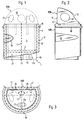
- the generally designated 1 in Fig. 1 freezer has a freezer 2 with a horizontal bottom wall 3 and one of the latter vertically upwards extending peripheral wall 4, which has an upper side open receiving space 5 for the Define frozen food, which bounded by the top side, of the peripheral wall 4 Access opening or removal opening is accessible.
- the bottom wall 3 and the Peripheral wall 4 are thermally insulated, which in the figures 1 and 3 by a suggestively illustrated insulation 8 is illustrated.
- the freezer container 2 has a circular arc section in the horizontal section Cross-sectional shape, wherein the flattening A forming secant beyond the Center axis 11 of the circular arc is arranged.
- This is a arcuate portion-shaped peripheral wall portion 6a and a secantial Circumferential wall portion 6b formed. The latter extends in the area of a blunt Winkels W of z. B. 120 °.
- the freezer 1 is suitable for the provision of frozen food both in enclosed spaces such as shopping malls, waiting rooms, canteens etc as well Streets and squares, especially for a street sale.
- a generally designated 9 and in Fig. 1 suggestively illustrated cover can have one or more through holes 12 of such size that a manual Penetration and the removal of a frozen goods is possible. This is despite good Accessibility to the receiving space 5, a partial cover of the removal opening. 7 guaranteed.
- the energy demand is caused by a cold accumulation caused by the cover significantly lowered.
- the access opening 7 with a windbreak Assign access openings 12 the receiving space 5 from wind largely protects.
- FIG. 1 to 6 is the protection by a dome or Hood formed in adaptation to the cross-sectional shape of the freezer container 2 a ball-shaped shape having a horizontal ball cutout side 13 and an approximately with the peripheral peripheral wall portion 6b aligned and slightly behind inside offset spherical section side 14.
- the approximately vertical ball cutout page 14 can be open or preferably closed by a hood wall.
- the freezer 1 is in a conventional manner, a cooling device with a Deep-freezing unit 15 and a deep-frozen body, not shown, in the receiving space. 5 assigned, which is connected by coolant lines to the freezer unit 15.
- the freezer unit 15 is preferably arranged in the cavity of a base 16, on which is the freezer 2.
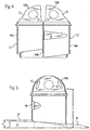
- the freezer 1 is also advantageous to arrange the freezer 1 on wheels 17, so that it from one can be moved to another location.
- the wheels 17 are preferably in Base 16 so freely rotatably mounted that they project beyond the base 16 down. hereby the required ground clearance between the bottom and the base 16 is created.
- three wheels 17 are provided, of which two wheels 17 on a close and parallel to the peripheral peripheral wall portion 6b extending Rotary axis 17a are freely rotatably mounted while the third wheel 17 in a for Front offset and central position on a rotation axis 17b freely rotatable is stored.
- possibly fold-out Be provided handles on which the freezer 1 when moving on the wheels 17th can be taken.
- a bumper 18, here in the sense of a railing to arrange, if necessary, the can form the above-described handles.
- a window 19 in the peripheral wall 6, is advantageous and promotional to arrange a window 19 in the peripheral wall 6, through the z. B. Children look into the receiving space 5 and on the frozen food can.
- a window 19 in the circular arc portion-shaped peripheral wall portion 6 a provided which is from the Transition region to the peripheral peripheral wall portion 6b, starting over a Part of the circular arc portion-shaped peripheral portion 6a extends.
- the window 19 is through a pane of transparent material such as glass or plastic locked.
- it is an insulating window, in particular with a Space between at least two windows.
- the embodiment of the invention makes it possible, two preferably the same Freezer 1 set up in a block arrangement in which they with their secant Peripheral wall sections 6b abut each other. As a result, the small Take-up capacity for the frozen food doubled, with good accessibility to the Recording room 5 is given.
- the freezer 2 With a height for adults, the freezer 2 has a predetermined Access height h, which allows a handle-friendly overlap.
- the freezer 1 an all-sided or one-sided pedestal 21 in such Height h1 to order that a child standing on it handling in the Recording room 5 is able to intervene.
- the pedestal 21 For children of different sizes it is beneficial to provide the pedestal 21 with a staircase or an inclined ramp 22 on which the Children can get on and off.
- the stairs or ramp 22 can turn in Circumferential direction of the refrigerator 1 extend. As a result, it takes up little space in Claim.
- such a pedestal 21 is in the range the arcuate peripheral wall portion 6a arranged, preferably with a inclined ramp 22, which allows different levels of access.
- the peripheral wall 4 isolated.
- the resulting wall thickening preferably extends to the pedestal 21 or to the ramp 22. In the absence of a Ramp 22 results in the wall thickening a helical boundary.
- the freezer 1 is assigned a screen 23, the umbrella rod with a fastening device, in particular a Plug connection with the freezer container 2 is connectable, preferably with the upper Area of the peripheral wall 4.
- the connector 24 through one or two upper side open plug-in holes 25 ( Figure 3) in the peripheral wall 4, preferably in the region of the peripheral peripheral wall section 6b and by one or two therein plugged with movement play sockets 27 formed on the plug foot 26.
- the freezer 1 is an upright panel 28 in one of Freezer 2 assigned uprising position, the one or both sides as Advertising space can be used.
- this can be the same Shoe 26 have, which is inserted by means of plug-in pins 27 in the plug holes 25. It can also for the screen 23 and the panel 28 certain fasteners on Freezer 2 may be provided which allow releasable fastening.
- the freezer container 2 a grid-shaped cover 31 which, by a plurality of horizontal, preferably in parallel mutually extending cover rods 32 may be formed, which is a removable Cover unit form, so that the receiving space 5 after removal of the cover 31st is accessible.
- cover 31 in one lateral hinge 33 to arrange folding and folding, the hinge axis 33a is preferably aligned parallel to the peripheral peripheral wall section 6b, wherein the flattening A nearest, circular cross-section support rod 32 the Joint pin of the associated joint can form.
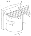
- An advantageous location for an inventive freezer 1 is z. B. on Cash registers of self-service restaurants or canteens.
- Such a stand shows Fig. 10, in which the freezer 1 is arranged next to a cash register 35, preferably between the cash register 35 and a cash passage 36.
- the Freezer 2 in the cash flow direction behind or in front of a tray slide Arrange 38, wherein the cover 31 of the freezer container 2 is an extension of the Tray slide 38 can form.
- This setup allows self-service in the Area of the cash register.
Landscapes
- Engineering & Computer Science (AREA)
- Physics & Mathematics (AREA)
- Thermal Sciences (AREA)
- Chemical & Material Sciences (AREA)
- Combustion & Propulsion (AREA)
- Mechanical Engineering (AREA)
- General Engineering & Computer Science (AREA)
- Freezing, Cooling And Drying Of Foods (AREA)
- Packages (AREA)
- Devices That Are Associated With Refrigeration Equipment (AREA)
- Confectionery (AREA)
Abstract
Description
Die Erfindung bezieht sich auf ein Tiefkühlgerät zur Bevorratung von Tiefkühlgut.The invention relates to a freezer for storing frozen food.
Ein Tiefkühlgerät dieser Art ist als quaderförmige Kühltruhe bekannt und wird z. B. in Einkaufsmärkten zur Bereitstellung von abgepackten Lebensmitteln genutzt. Die bekannte Bauweise weist ein kastenförmiges Gehäuse mit einer rechteckigen horizontalen Querschnittsform auf, dessen oberseitige Entnahmeöffnung durch einen Deckel wahlweise zu verschließen und zu öffnen ist. Für eine Aufstellung in einem Einkaufsmarkt oder dergleichen ist eine rechteckförmige horizontale Querschnittsform als längliches Rechteck üblich, um bei einer Aufstellung zwischen zwei Zugangswegen bei Gewährleistung der Zugänglichkeit von beiden Breitseiten her einen Aufnahmeraum mit einem möglichst großen Volumen für das Tiefkühlgut zu schaffen. Es ist bei dieser bekannten Bauform auch möglich, das Tiefkühlgerät mit einer Breitseite an einer Wand aufzustellen, wobei es von der anderen Breitseite her zugänglich ist. Diese bekannte Bauform eignet sich jedoch nicht für Aufstellplätze geringer Größe, da die längliche und viereckige Form einer günstigen Aufstellung und Platzausnutzung entgegensteht. A freezer of this type is known as a cuboid freezer and z. In Used for the provision of pre-packaged food. The well-known Construction has a box-shaped housing with a rectangular horizontal Cross-sectional shape, the top-side removal opening by a lid optional to close and open. For a lineup in a shopping market or The like is a rectangular horizontal cross-sectional shape as an elongated rectangle usual in order to set up between two access routes while ensuring the Accessibility from both broad sides forth a recording room with a possible to create large volumes for the frozen goods. It is in this known design also possible to set up the freezer with a broadside on a wall, where it accessible from the other broadside. However, this known design is suitable not for small size squares, as the elongated and quadrangular shape of a precludes favorable installation and space utilization.
In der US-A-2 279 558 ist ein Kühlgerät mit einem Kühlbehälter beschrieben, der von zwei einander gegenüberliegenden Seiten zugänglich ist, an seiner Frontseite eine erste Zugangsöffnung zum Aufnahmeraum des Kühlbehälters und an seiner gegenüberliegenden Rückseite eine zweite Zugangsöffnung zur Entnahme von Frostrückständen aufweist. Dabei ist die Frontseite im horizontalen Querschnitt gerundet ausgebildet, während die Rückseite eine ebene Rückenfläche hat, von der ein Deckel für die zweite Zugangsöffnung vorsteht. Zum einen wegen der Zugänglichkeit und zum anderen wegen des Vorstehens des Deckels an der zweiten Zugangsöffnung ist dies bekannte Kühlgerät nicht geeignet, mit seiner flachen Rückseitenfläche an eine Wand gestellt zu werden.In US-A-2 279 558 is a refrigerator with a Cooling container described by two each other opposite sides is accessible at his Front side a first access opening to the receiving space of the Cooling container and on its opposite Rear side a second access opening for removal of Having frost residues. Here is the front in the horizontal cross section formed rounded, while the Back has a flat back surface, from which a lid protrudes for the second access opening. For one thing the accessibility and on the other hand because of the projection the lid on the second access opening is this known refrigerator not suitable, with its flat Rear surface to be placed on a wall.
Aus der US-A-5 413 245 ist ein Kühlgerät zu entnehmen, bei dem die Umfangswand des Kühlbehälters aus zwei einander gegenüberliegend angeordneten und um einander gegenüberliegend vertikal verlaufende Gelenkachsen drehbare Halbschalen besteht, die zum Öffnen nach außen geschwenkt werden und deshalb seitlichen Freiraum benötigen.From US-A-5 413 245 a cooling device can be seen, wherein the peripheral wall of the cooling tank of two arranged opposite each other and around each other opposite vertical axes of articulation rotatable half-shells is made to open to the outside be pivoted and therefore lateral clearance need.
US-A-5 596 880 zeigt ein Kühlgerät mit einem hohlzylindrischen Kühlbehälter, von dessen Rückseite eine sich aufwärts erstreckende Abführungsleitung vorsteht und deshalb einen rückseitigen Freiraum erfordert. US-A-5 596 880 shows a cooling device with a hollow cylindrical Cooling tank, from the back one projecting upwardly extending discharge line and therefore requires a back space.
Der Erfindung liegt die Aufgabe zugrunde, ein Tiefkühlgerät der eingangs angegebenen Art so auszugestalten, daß eine bessere Platzausnutzung möglich ist.The invention is based on the object, a freezer of the aforementioned To design a way so that a better space utilization is possible.
Diese Aufgabe wird durch die Merkmale des Anspruchs 1 gelöst.This object is solved by the features of
Bei der erfindungsgemäßen Ausgestaltung weist das Tiefkühlgerät im horizontalen Schnitt eine einseitig abgeflachte runde Querschnittsform auf wobei die Umfangswand in Form einer hohlzylinderförmigen runden Grundform ausgebildet ist, deren Mantelfläche eine Abflachung aufweist, die sich parallel zu einer durch den Mittelpunkt der runden Grundform verlaufenden Mittelachse erstreckt und durch einen sekantialen Umfangswandabschnitt gebildet ist. Hierdurch eignet sich das Tiefkühlgerät für eine Aufstellung sowohl an einer Wand als auch im freien Raum. Dabei ist unter Berücksichtigung der Größe eines die Zugänglichkeit zum Aufnahmeraum gewährleistenden Radius eine verhältnismäßig kleine Baugröße möglich, so daß das Tiefkühlgerät sich nicht nur für die Aufstellung an kleinen Aufstellungsplätzen eignet, sondern auch an größeren Aufstellungsplätzen, wobei sich dann jeweils zwei Tiefkühlgeräte in Blockanordnung mit ihren Abflachungen aneinander stellen lassen. Ein weiterer Vorteil der erfindungsgemäßen Ausgestaltung besteht darin, daß im Bereich der gerundeten Umfangswand Ecken entfallen und deshalb eine sperrige Bauweise vermieden und eine gute Zugänglichkeit gewährleistet ist.In the embodiment according to the invention, the freezer in horizontal section a one-sided flattened round cross-sectional shape on the peripheral wall is in the form of a hollow cylindrical circular basic shape, the lateral surface has a flattening, which extends parallel to a center axis extending through the center of the circular shape and is formed by a secant peripheral wall portion. This makes the freezer for a Posing on a wall as well as in free space. It is under Considering the size of the accessibility to the receiving space ensuring radius a relatively small size possible, so that the Freezer is not only suitable for installation in small locations, but also at larger sites, then each two Freeze units in block arrangement with their flattenings put together. One Another advantage of the embodiment of the invention is that in the field of Rounded peripheral wall corners omitted and therefore avoided a bulky design and good accessibility is ensured.
Das erfindungsgemäße Tiefkühlgerät eignet sich somit zur Aufstellung sowohl in Räumen als auch auf Straßen und Plätzen, wobei aufgrund der verhältnismäßig geringen Baugröße ein verhältnismäßig geringes Gewicht gegeben ist und sich das Tiefkühlgerät deshalb verhältnismäßig leicht transportieren läßt, um auf verschiedenen Plätzen aufgestellt zu werden, z. B. für einen Straßenverkauf des Tiefkühlguts. Für den zuletzt genannten Zweck ist es vorteilhaft, das Tiefkühlgerät mit Rädern zu versehen, so daß es zwischen verschiedenen Aufstellungsorten verfahrbar ist.The freezer according to the invention is thus suitable for installation both in rooms as well as on streets and squares, due to the relatively small size a relatively low weight is given and the freezer therefore relatively easy to transport to different places be, for. B. for a street sale of frozen goods. For the last purpose it is advantageous to provide the freezer with wheels, so that it between various sites is movable.
Die erfindungsgemäße Bauform ist auch energiesparend, da sie sich im horizontalen Querschnitt einer runden Form nähert, bei der das Verhältnis zwischen Oberfläche und Volumen günstig ist. In den Unteransprüchen enthaltende Merkmale führen zu einfachen Ausgestaltungen einer vorteilhaften Abdeckung des Kühlgeräts und einer Befestigungsmöglichkeit für einen Schirm. Für Kinder wird durch ein Fenster in der Umfangswand des Tiefkühlgeräts ein Einblick auf das im Aufnahmeraum des Tiefkühlgeräts befindliche Tiefkühlgut ermöglicht.The design of the invention is also energy efficient, as they are horizontal Cross section of a round shape approximates, where the relationship between surface and Volume is low. In the subclaims containing features lead to simple Embodiments of an advantageous cover of the refrigerator and a Mounting option for a screen. For children is through a window in the Peripheral wall of the freezer gives an insight into the in the receiving space of the Freezer available frozen food allows.
Nachfolgend werden die Erfindung und weitere durch sie erzielbare Vorteile anhand von bevorzugten Ausgestaltungen und Zeichnungen näher erläutert. Es zeigen:
- Fig. 1
- ein erfindungsgemäßes Tiefkühlgerät in der Vorderansicht;
- Fig. 2
- das Tiefkühlgerät nach Fig. 1 in der Seitenansicht von links;
- Fig. 3
- das Tiefkühlgerät nach Fig. 1 in der Draufsicht;
- Fig. 4
- zwei gleiche Tiefkühlgeräte in einer an ihren Abflachungen aneinander gestellter Blockstellung;
- Fig. 5
- das Tiefkühlgerät in der Vorderansicht in abgewandelter Ausgestaltung;
- Fig. 6
- ein erfindungsgemäßes Tiefkühlgerät in perspektivischer Vorderansicht in einer weiter abgewandelter Ausgestaltung;
- Fig. 7
- ein erfindungsgemäßes Tiefkühlgerät in der Vorderansicht in einer weiter abgewandelter Ausgestaltung;
- Fig. 8
- das Tiefkühlgerät nach Fig. 7 in der Seitenansicht von links;
- Fig. 9
- das Tiefkühlgerät nach Fig. 7 in der Draufsicht; und
- Fig. 10
- das Tiefkühlgerät nach Fig. 7 an einem besonderen Aufstellungsort z. B. an einer Kasse eines Selbstbedienungsrestaurants.
- Fig. 1
- a freezer according to the invention in front view;
- Fig. 2
- the freezer of Figure 1 in the side view from the left.
- Fig. 3
- the freezer of Figure 1 in plan view.
- Fig. 4
- two identical freezers in a juxtaposed on their flats block position;
- Fig. 5
- the freezer in the front view in a modified embodiment;
- Fig. 6
- an inventive freezer in a perspective front view in a further modified embodiment;
- Fig. 7
- an inventive freezer in the front view in a further modified embodiment;
- Fig. 8
- the freezer of Figure 7 in the side view from the left.
- Fig. 9
- the freezer of Figure 7 in plan view. and
- Fig. 10
- the freezer of FIG. 7 at a particular site z. B. at a checkout of a self-service restaurant.
Das in Fig. 1 allgemein mit 1 bezeichnete Tiefkühlgerät weist einen Tiefkühlbehälter 2 mit
einer horizontalen Bodenwand 3 und einer sich von letzterer vertikal nach oben
erstreckenden Umfangswand 4 auf, die einen oberseitig offenen Aufnahmeraum 5 für das
Tiefkühlgut begrenzen, der durch die oberseitige, von der Umfangswand 4 umgrenzte
Zugangsöffnung oder Entnahmeöffnung zugänglich ist. Die Bodenwand 3 und die
Umfangswand 4 sind wärmeisoliert, was in den Figuren 1 und 3 durch eine
andeutungsweise dargestellte Isolierung 8 verdeutlicht ist.The generally designated 1 in Fig. 1 freezer has a
Der Tiefkühlbehälter 2 weist im horizontalen Schnitt eine kreisbogenabschnittförmige
Querschnittsform auf, wobei die eine Abflachung A bildende Sekante jenseits der
Mittelachse 11 des Kreisbogens angeordnet ist. Hierdurch sind ein
kreisbogenabschnittförmiger Umfangswandabschnitt 6a und ein sekantialer
Umfangswandabschnitt 6b gebildet. Letzterer erstreckt sich im Bereich eines stumpfen
Winkels W von z. B. 120 °.The
Das Tiefkühlgerät 1 eignet sich zur Bereitstellung von Tiefkühlgut sowohl in
geschlossenen Räumen wie Einkaufsmärkten, Warteräumen, Kantinen usw. als auch auf
Straßen und Plätzen, insbesondere für einen Straßenverkauf.The
Ein allgemein mit 9 bezeichneter und in Fig. 1 andeutungsweise dargestellter Deckel kann
ein oder mehrere Durchgriffslöcher 12 solcher Größe aufweisen, daß ein manueller
Durchgriff und die Entnahme eines Tiefkühlgutteils möglich ist. Hierdurch ist trotz guter
Zugänglichkeit zum Aufnahmeraum 5 eine teilweise Abdeckung der Entnahmeöffnung 7
gewährleistet.A generally designated 9 and in Fig. 1 suggestively illustrated cover can
have one or more through
Der Energiebedarf wird durch einen durch die Abdeckung hervorgerufenen Kältestau
deutlich gesenkt. Insbesondere für eine Aufstellung des Tiefkühlgeräts 1 auf Straßen und
Plätzen ist es vorteilhaft, der Zugangsöffnung 7 einen Windschutz mit
Durchgrifföffnungen 12 zuzuordnen, der den Aufnahmeraum 5 vor Wind weitgehend
schützt.The energy demand is caused by a cold accumulation caused by the cover
significantly lowered. In particular for a list of the
Bei den Ausgestaltungen gemäß Figuren 1 bis 6 ist der Schutz durch eine Kuppel oder
Haube gebildet, die in Anpassung an die Querschnittsform des Tiefkühlbehälters 2 eine
kugelausschnittförmige Form aufweist mit einer horizontalen Kugelausschnittseite 13 und
einer etwa mit dem sekantialen Umfangswandabschnitt 6b fluchtenden und etwas nach
innen versetzten Kugelabschnittsseite 14. Die etwa vertikale Kugelausschnittseite 14 kann
offen oder vorzugsweise durch eine Haubenwand geschlossen sein.In the embodiments of Figures 1 to 6 is the protection by a dome or
Hood formed in adaptation to the cross-sectional shape of the freezer container 2 a
ball-shaped shape having a horizontal
Dem Tiefkühlgerät 1 ist in an sich bekannter Weise eine Kühleinrichtung mit einem
Tiefkühlaggregat 15 und einem nicht dargestellten Tiefkühlkörper im Aufnahmeraum 5
zugeordnet, der durch Kühlmittelleitungen mit dem Tiefkühlaggregat 15 verbunden ist.
Das Tiefkühlaggregat 15 ist vorzugsweise im Hohlraum eines Sockels 16 angeordnet, auf
dem der Tiefkühlbehälter 2 steht.The
Es ist außerdem vorteilhaft, das Tiefkühlgerät 1 auf Rädern 17 anzuordnen, so daß es von
einem zum anderen Aufstellplatz verfahrbar ist. Die Räder 17 sind vorzugsweise im
Sockel 16 so frei drehbar gelagert, daß sie den Sockel 16 nach unten überragen. Hierdurch
ist die erforderliche Bodenfreiheit zwischen dem Boden und dem Sockel 16 geschaffen.
Bei der vorliegenden Ausgestaltung sind drei Räder 17 vorgesehen, von denen zwei Räder
17 auf einer nahe und parallel zum sekantialen Umfangswandabschnitt 6b verlaufende
Drehachse 17a frei drehbar gelagert sind, während das dritte Rad 17 in einer zur
Vorderseite hin versetzten und mittigen Position auf einer Drehachse 17b frei drehbar
gelagert ist. Im Bereich des sekantialen Umfangswandabschnitts 6b und/oder
gegenüberliegend können an der Umfangswand 4 nicht dargestellte, ggf. ausklappbare
Griffe vorgesehen sein, an denen das Tiefkühlgerät 1 beim Verfahren auf den Rädern 17
ergriffen werden kann. Um den Tiefkühlbehälter 2 insbesondere beim Verfahren vor
Stoßbeschädigungen an der Außenseite zu schützen, ist es vorteilhaft, an der
Umfangswand 4 eine Stoßstange 18, hier im Sinne einer Reling, anzuordnen, die ggf. die
vorbeschriebenen Griffe bilden kann.It is also advantageous to arrange the
Es ist vorteilhaft und verkaufsfördernd, in der Umfangswand 6 ein Fenster 19 anzuordnen,
durch das hindurch z. B. Kinder in den Aufnahmeraum 5 und auf das Tiefkühlgut blicken
können. Bei der vorliegenden Ausgestaltung ist ein Fenster 19 in der
kreisbogenabschnittförmigen Umfangswandabschnitt 6a vorgesehen, wobei es sich vom
Übergangsbereich zum sekantialen Umfangswandabschnitt 6b ausgehend über einen
Teilbereich des kreisbogenabschnittförmigen Umfangsabschnitts 6a erstreckt. Das Fenster
19 ist durch eine Scheibe aus transparentem Material wie Glas oder Kunststoff
verschlossen. Vorzugsweise handelt es sich um ein Isolierfenster, insbesondere mit einem
Zwischenraum zwischen wenigstens zwei Fensterscheiben.It is advantageous and promotional to arrange a
Die erfindungsgemäße Ausgestaltung ermöglicht es, zwei vorzugsweise gleich ausgebildete
Tiefkühlgeräte 1 in einer Blockanordnung aufzustellen, in der sie mit ihren sekantialen
Umfangswandabschnitten 6b aneinanderliegen. Hierdurch wird auf kleinem Stellraum die
Aufnahmekapazität für das Tiefkühlgut verdoppelt, wobei eine gute Zugänglichkeit zum
Aufnahmeraum 5 gegeben ist.The embodiment of the invention makes it possible, two preferably the
Bei einer Bauhöhe für Erwachsene weist der Tiefkühlbehälter 2 eine vorbestimmte
Zugriffshöhe h auf, die ein handhabungsfreundliches Übergreifen ermöglicht. Um auch für
Kinder einen handhabungsfreundlichen Zugriff zum Tiefkühlgut zu gewährleisten, ist es
vorteilhaft, am Tiefkühlgerät 1 ein allseitiges oder einseitiges Podest 21 in einer solchen
Höhe h1 anzuordnen, daß ein darauf stehendes Kind handhabungsgünstig in den
Aufnahmeraum 5 einzugreifen vermag. Für unterschiedlich große Kinder ist es vorteilhaft,
das Podest 21 mit einer Treppe oder einer schrägen Rampe 22 zu versehen, auf denen die
Kinder auf- und absteigen können. Die Treppe oder Rampe 22 kann sich in
Umfangsrichtung des Kühlgeräts 1 erstrecken. Hierdurch nimmt sie wenig Platz in
Anspruch. Bei der Ausgestaltung gemäß der Fig. 5 ist ein solches Podest 21 im Bereich
des bogenförmigen Umfangswandabschnitts 6a angeordnet, vorzugsweise mit einer
geneigten Rampe 22, die unterschiedliche Zugriffshöhen ermöglicht. Bei der vorliegenden
Ausgestaltung ist die Umfangswand 4 isoliert. Die dadurch vorgegebene Wandverdickung
erstreckt sich vorzugsweise bis zum Podest 21 oder bis zur Rampe 22. Beim Fehlen einer
Rampe 22 ergibt sich für die Wandverdickung eine wendelförmige Begrenzung.With a height for adults, the
Beim Ausführungsbeispiel nach Fig. 6 ist dem Tiefkühlgerät 1 ein Schirm 23 zugeordnet,
dessen Schirmstange mit einer Befestigungsvorrichtung, insbesondere einer
Steckverbindung mit dem Tiefkühlbehälter 2 verbindbar ist, vorzugsweise mit dem oberen
Bereich der Umfangswand 4. Bei der vorliegenden Ausgestaltung ist die Steckverbindung
24 durch ein oder zwei oberseitig offene Stecklöcher 25 (Fig. 3) in der Umfangswand 4,
vorzugsweise im Bereich des sekantialen Umfangswandabschnitts 6b und durch ein oder
zwei darin mit Bewegungsspiel ansteckbare Steckdorne 27 am Steckfuß 26 gebildet.In the embodiment according to FIG. 6, the
Außerdem ist dem Tiefkühlgerät 1 eine aufrecht stehende Tafel 28 in einer vom
Tiefkühlbehälter 2 aufragenden Position zugeordnet, die ein- oder beidseitig als
Werbefläche genutzt werden kann. Zur Befestigung der Tafel 28 kann diese einen gleichen
Steckfuß 26 aufweisen, der mittels Steckdornen 27 in die Stecklöcher 25 einsteckbar ist.
Es können auch für den Schirm 23 und die Tafel 28 bestimmte Befestigungselemente am
Tiefkühlbehälter 2 vorgesehen sein, die ein lösbares Befestigen ermöglichen.In addition, the
Beim Ausführungsbeispiel nach den Figuren 7 bis 10, bei dem gleiche oder vergleichbare
Teile mit gleichen Bezugszeichen versehen sind, weist der Tiefkühlbehälter 2 eine
gitterförmige Abdeckung 31 auf, die durch mehrere horizontale, vorzugsweise parallel
zueinander verlaufende Abdeckstangen 32 gebildet sein kann, die eine abnehmbare
Abdeckeinheit bilden, so daß der Aufnahmeraum 5 nach Entnahme der Abdeckung 31
zugänglich ist. Eine vorteilhafte Variante besteht darin, die Abdeckung 31 in einem
seitlichen Gelenk 33 auf- und abklappbar anzuordnen, dessen Gelenkachse 33a
vorzugsweise parallel zum sekantialen Umfangswandabschnitt 6b ausgerichtet ist, wobei
die der Abflachung A nächstliegende, im Querschnitt kreisrunde Tragstange 32 den
Gelenkbolzen des zugehörigen Gelenks bilden kann.In the embodiment of Figures 7 to 10, in the same or similar
Parts are provided with the same reference numerals, the freezer container 2 a
grid-shaped
Ein vorteilhafter Aufstellplatz für ein erfindungsgemäßes Tiefkühlgerät 1 ist z. B. an
Kassen von Selbstbedienungsrestaurants oder Kantinen. Einen solchen Standplatz zeigt
Fig. 10, bei der das Tiefkühlgerät 1 neben einer Kasse 35 angeordnet ist, vorzugsweise
zwischen der Kasse 35 und einem Kassendurchgang 36. Dabei ist es vorteilhaft, den
Tiefkühlbehälter 2 in der Kassendurchgangsrichtung hinter oder vor einer Tablettrutsche
38 anzuordnen, wobei die Abdeckung 31 des Tiefkühlbehälters 2 eine Verlängerung der
Tablettrutsche 38 bilden kann. Diese Aufstellung ermöglicht eine Selbstbedienung im
Bereich der Kasse.An advantageous location for an
Claims (12)
- Deep-freezing appliance (1) for stocking deep-frozen products, in particular prepacked foods such as ice cream, said appliance having a deep-freezing container (2), which is accessible via at least one removal aperture (7) and has a thermally insulating peripheral wall (4), and a deep-freezing unit (15) for deep-freezing the holding compartment (5) of the deep-freezing container (2),
wherein the peripheral wall (4) of the deep-freezing container (2) is constructed in the form of a hollow-cylindrical, round basic shape whose superficies has a flattened portion (A) which extends parallel to a central axis (11) extending through the centre of the round basic shape and is formed by a secantial peripheral-wall section (6b). - Deep-freezing appliance according to claim 1,
characterised in that
the deep-freezing container (2) has a hood (9a) which is curved convexly outwards. - Deep-freezing appliance according to claim 2,
characterised in that
the hood (9a) consists of a transparent material such as glass or plastic. - Deep-freezing appliance according to claim 2 or 3,
characterised in that
the hood (9a) has one or more removal apertures (12). - Deep-freezing appliance according to claim 4,
characterised in that
a number of removal apertures (12) are disposed in the lower region of the hood (9a) in a manner distributed over the periphery. - Deep-freezing appliance according to one of the preceding claims 2 to 5,
characterised in that
the hood (9a) has a spherical curvature. - Deep-freezing appliance according to one of claims 2 to 6,
characterised in that,
on the side on which the flattened portion (A) is located, the hood (9a) has a lateral face (14) which is in alignment with said flattened portion (A) or is inclined towards the side that faces away from said flattened portion (A). - Deep-freezing appliance according to one of the preceding claims,
characterised in that
a window (19) is disposed in the peripheral wall (4) or in a hollow-cylindrical section (6a) of said peripheral wall (4). - Deep-freezing appliance according to one of the preceding claims
characterised in that
the deep-freezing appliance (1) has wheels (17) and is movable. - Deep-freezing appliance according to claim 9,
characterised in that
the swivel pins of the wheels (17) extend parallel to the flattened portion (A). - Deep-freezing appliance according to one of the preceding claims,
characterised in that
a fastening means or at least a plug-in hole (25) for an umbrella (23) and/or an advertising-space carrier (28) is disposed on the peripheral wall (4), particularly in the upper region of the latter. - Deep-freezing appliance according to one of the preceding claims,
characterised in that
the deep-freezing container (2) has, on its upper side, a cover (31) having covering bars (32) which combine to form a lattice grid and are oriented parallel to the flattened portion (A).
Applications Claiming Priority (2)
| Application Number | Priority Date | Filing Date | Title |
|---|---|---|---|
| DE29716713U DE29716713U1 (en) | 1997-09-17 | 1997-09-17 | Freezer for storing frozen goods |
| DE29716713U | 1997-09-17 |
Publications (3)
| Publication Number | Publication Date |
|---|---|
| EP0903548A2 EP0903548A2 (en) | 1999-03-24 |
| EP0903548A3 EP0903548A3 (en) | 2001-10-17 |
| EP0903548B1 true EP0903548B1 (en) | 2005-08-17 |
Family
ID=8046129
Family Applications (1)
| Application Number | Title | Priority Date | Filing Date |
|---|---|---|---|
| EP98117478A Expired - Lifetime EP0903548B1 (en) | 1997-09-17 | 1998-09-15 | Freezing apparatus for supplying frozen products |
Country Status (5)
| Country | Link |
|---|---|
| EP (1) | EP0903548B1 (en) |
| AT (1) | ATE302397T1 (en) |
| DE (2) | DE29716713U1 (en) |
| DK (1) | DK0903548T3 (en) |
| ES (1) | ES2248868T3 (en) |
Families Citing this family (1)
| Publication number | Priority date | Publication date | Assignee | Title |
|---|---|---|---|---|
| EP0966640B1 (en) * | 1997-02-20 | 2002-06-05 | Unilever Plc | Housing for freezer cabinets, and housing system |
Family Cites Families (5)
| Publication number | Priority date | Publication date | Assignee | Title |
|---|---|---|---|---|
| US2279558A (en) * | 1940-09-20 | 1942-04-14 | Leonard F Clerc | Refrigeration device |
| DE3247219A1 (en) * | 1982-12-20 | 1984-06-20 | Walter 6500 Finthen Becker | Rotatable table attachment for enlarging the table area |
| US4946032A (en) * | 1989-06-14 | 1990-08-07 | The Mead Corporation | Display cooler |
| US5413245A (en) * | 1992-01-22 | 1995-05-09 | Wright Food Systems, Inc. | Vending system having improved vending access and identification |
| US5596880A (en) * | 1994-02-14 | 1997-01-28 | Decision Point Marketing | Chilled beverage display container |
-
1997
- 1997-09-17 DE DE29716713U patent/DE29716713U1/en not_active Expired - Lifetime
-
1998
- 1998-09-15 DK DK98117478T patent/DK0903548T3/en active
- 1998-09-15 AT AT98117478T patent/ATE302397T1/en not_active IP Right Cessation
- 1998-09-15 ES ES98117478T patent/ES2248868T3/en not_active Expired - Lifetime
- 1998-09-15 EP EP98117478A patent/EP0903548B1/en not_active Expired - Lifetime
- 1998-09-15 DE DE59813005T patent/DE59813005D1/en not_active Expired - Fee Related
Also Published As
| Publication number | Publication date |
|---|---|
| DK0903548T3 (en) | 2005-09-19 |
| DE29716713U1 (en) | 1997-11-27 |
| ES2248868T3 (en) | 2006-03-16 |
| EP0903548A2 (en) | 1999-03-24 |
| EP0903548A3 (en) | 2001-10-17 |
| DE59813005D1 (en) | 2005-09-22 |
| ATE302397T1 (en) | 2005-09-15 |
Similar Documents
| Publication | Publication Date | Title |
|---|---|---|
| EP1032797B1 (en) | Refrigerating device | |
| DE2846272A1 (en) | MOBILE SALES STAND | |
| EP1984687A2 (en) | Refrigeration device comprising shelves | |
| EP0903548B1 (en) | Freezing apparatus for supplying frozen products | |
| DE19740900C2 (en) | Freezer for frozen products | |
| DE602004004045T2 (en) | display case | |
| DE202013001178U1 (en) | Device for presenting goods and the like and shop counter therewith | |
| DE19740902C2 (en) | Freezer for storing frozen goods, especially for packaged foods such as ice cream | |
| DE19903958C2 (en) | Cooling storage system | |
| DE202017104343U1 (en) | refrigeration cabinets | |
| DE4344310A1 (en) | Cold chest for display of food in supermarket | |
| DE69903509T2 (en) | Shelf for vertical freezer | |
| EP0172942B1 (en) | Shop counter, in particular for a pharmacy | |
| DE3843247C1 (en) | Display counter | |
| DE4301148C2 (en) | Freezer island | |
| DE202008015867U1 (en) | Device, in particular, for bidding on and displaying a product | |
| DE29815533U1 (en) | Variable, mobile showcase system | |
| DE102004015776B4 (en) | Device for the increased presentation of food objects | |
| DE4004747A1 (en) | Refrigerated sales cabinet for goods - has three adjacent refrigerators, with top glass covered compartment | |
| DE29711659U1 (en) | Serving trolley | |
| DE2803576A1 (en) | Sales counter for cut flowers - incorporates refrigeration unit, trough shaped watertight container, and water inlet and outlet | |
| DE1993948U (en) | REFRIGERATED UNITS WITH OPTIONALLY CHANGEABLE CONSTRUCTION. | |
| DE7831660U1 (en) | MOBILE SALES STAND | |
| DE3522750A1 (en) | Deep-freeze device for the direct sale of deep-frozen articles stacked on pallets | |
| EP0067241A1 (en) | Freezer |
Legal Events
| Date | Code | Title | Description |
|---|---|---|---|
| PUAI | Public reference made under article 153(3) epc to a published international application that has entered the european phase |
Free format text: ORIGINAL CODE: 0009012 |
|
| AK | Designated contracting states |
Kind code of ref document: A2 Designated state(s): AT BE CH CY DE DK ES FI FR GB GR IE IT LI LU MC NL PT SE |
|
| AX | Request for extension of the european patent |
Free format text: AL;LT;LV;MK;RO;SI |
|
| PUAL | Search report despatched |
Free format text: ORIGINAL CODE: 0009013 |
|
| AK | Designated contracting states |
Kind code of ref document: A3 Designated state(s): AT BE CH CY DE DK ES FI FR GB GR IE IT LI LU MC NL PT SE |
|
| AX | Request for extension of the european patent |
Free format text: AL;LT;LV;MK;RO;SI |
|
| 17P | Request for examination filed |
Effective date: 20020220 |
|
| AKX | Designation fees paid |
Free format text: AT BE CH CY DE DK ES FI FR GB GR IE IT LI LU MC NL PT SE |
|
| AXX | Extension fees paid |
Free format text: AL PAYMENT 20020220;LT PAYMENT 20020220;LV PAYMENT 20020220;MK PAYMENT 20020220;RO PAYMENT 20020220;SI PAYMENT 20020220 |
|
| 17Q | First examination report despatched |
Effective date: 20030912 |
|
| RAP1 | Party data changed (applicant data changed or rights of an application transferred) |
Owner name: NESTEC S.A. |
|
| GRAP | Despatch of communication of intention to grant a patent |
Free format text: ORIGINAL CODE: EPIDOSNIGR1 |
|
| RIN1 | Information on inventor provided before grant (corrected) |
Inventor name: REHKLAU, ANDREAS Inventor name: STAUCH, RUEDIGER Inventor name: NEUMANN, UWE Inventor name: LINDE, HANSJUERGEN, PROF. DR.-ING. Inventor name: KOHLHOFF, CLAUDIA Inventor name: MAUL, ANDREA Inventor name: OCKER, FRANK Inventor name: FAISST, PETER Inventor name: VORNDRAN, THOMAS Inventor name: SCHOPPER, RICHARD Inventor name: GOETTFERT, THOMAS Inventor name: BEER, RICHARD |
|
| GRAS | Grant fee paid |
Free format text: ORIGINAL CODE: EPIDOSNIGR3 |
|
| GRAA | (expected) grant |
Free format text: ORIGINAL CODE: 0009210 |
|
| AK | Designated contracting states |
Kind code of ref document: B1 Designated state(s): AT BE CH CY DE DK ES FI FR GB GR IE IT LI LU MC NL PT SE |
|
| AX | Request for extension of the european patent |
Extension state: AL LT LV MK RO SI |
|
| PG25 | Lapsed in a contracting state [announced via postgrant information from national office to epo] |
Ref country code: NL Free format text: LAPSE BECAUSE OF FAILURE TO SUBMIT A TRANSLATION OF THE DESCRIPTION OR TO PAY THE FEE WITHIN THE PRESCRIBED TIME-LIMIT Effective date: 20050817 Ref country code: IE Free format text: LAPSE BECAUSE OF FAILURE TO SUBMIT A TRANSLATION OF THE DESCRIPTION OR TO PAY THE FEE WITHIN THE PRESCRIBED TIME-LIMIT Effective date: 20050817 |
|
| REG | Reference to a national code |
Ref country code: GB Ref legal event code: FG4D Free format text: NOT ENGLISH |
|
| REG | Reference to a national code |
Ref country code: CH Ref legal event code: EP |
|
| PG25 | Lapsed in a contracting state [announced via postgrant information from national office to epo] |
Ref country code: CY Free format text: LAPSE BECAUSE OF FAILURE TO SUBMIT A TRANSLATION OF THE DESCRIPTION OR TO PAY THE FEE WITHIN THE PRESCRIBED TIME-LIMIT Effective date: 20050915 Ref country code: AT Free format text: LAPSE BECAUSE OF NON-PAYMENT OF DUE FEES Effective date: 20050915 |
|
| REG | Reference to a national code |
Ref country code: DK Ref legal event code: T3 |
|
| REG | Reference to a national code |
Ref country code: IE Ref legal event code: FG4D Free format text: LANGUAGE OF EP DOCUMENT: GERMAN |
|
| REF | Corresponds to: |
Ref document number: 59813005 Country of ref document: DE Date of ref document: 20050922 Kind code of ref document: P |
|
| PG25 | Lapsed in a contracting state [announced via postgrant information from national office to epo] |
Ref country code: MC Free format text: LAPSE BECAUSE OF NON-PAYMENT OF DUE FEES Effective date: 20050930 Ref country code: BE Free format text: LAPSE BECAUSE OF NON-PAYMENT OF DUE FEES Effective date: 20050930 |
|
| PG25 | Lapsed in a contracting state [announced via postgrant information from national office to epo] |
Ref country code: LU Free format text: LAPSE BECAUSE OF NON-PAYMENT OF DUE FEES Effective date: 20051017 |
|
| PG25 | Lapsed in a contracting state [announced via postgrant information from national office to epo] |
Ref country code: SE Free format text: LAPSE BECAUSE OF FAILURE TO SUBMIT A TRANSLATION OF THE DESCRIPTION OR TO PAY THE FEE WITHIN THE PRESCRIBED TIME-LIMIT Effective date: 20051117 Ref country code: GR Free format text: LAPSE BECAUSE OF FAILURE TO SUBMIT A TRANSLATION OF THE DESCRIPTION OR TO PAY THE FEE WITHIN THE PRESCRIBED TIME-LIMIT Effective date: 20051117 |
|
| GBT | Gb: translation of ep patent filed (gb section 77(6)(a)/1977) | ||
| PG25 | Lapsed in a contracting state [announced via postgrant information from national office to epo] |
Ref country code: PT Free format text: LAPSE BECAUSE OF FAILURE TO SUBMIT A TRANSLATION OF THE DESCRIPTION OR TO PAY THE FEE WITHIN THE PRESCRIBED TIME-LIMIT Effective date: 20060117 |
|
| LTIE | Lt: invalidation of european patent or patent extension |
Effective date: 20050817 |
|
| NLV1 | Nl: lapsed or annulled due to failure to fulfill the requirements of art. 29p and 29m of the patents act | ||
| REG | Reference to a national code |
Ref country code: ES Ref legal event code: FG2A Ref document number: 2248868 Country of ref document: ES Kind code of ref document: T3 |
|
| REG | Reference to a national code |
Ref country code: IE Ref legal event code: FD4D |
|
| ET | Fr: translation filed | ||
| PLBE | No opposition filed within time limit |
Free format text: ORIGINAL CODE: 0009261 |
|
| STAA | Information on the status of an ep patent application or granted ep patent |
Free format text: STATUS: NO OPPOSITION FILED WITHIN TIME LIMIT |
|
| 26N | No opposition filed |
Effective date: 20060518 |
|
| PGFP | Annual fee paid to national office [announced via postgrant information from national office to epo] |
Ref country code: DE Payment date: 20070913 Year of fee payment: 10 |
|
| PGFP | Annual fee paid to national office [announced via postgrant information from national office to epo] |
Ref country code: DK Payment date: 20070914 Year of fee payment: 10 |
|
| PGFP | Annual fee paid to national office [announced via postgrant information from national office to epo] |
Ref country code: FI Payment date: 20070912 Year of fee payment: 10 Ref country code: CH Payment date: 20070913 Year of fee payment: 10 |
|
| BERE | Be: lapsed |
Owner name: NESTEC S.A. Effective date: 20050930 |
|
| PGFP | Annual fee paid to national office [announced via postgrant information from national office to epo] |
Ref country code: GB Payment date: 20070912 Year of fee payment: 10 |
|
| PGFP | Annual fee paid to national office [announced via postgrant information from national office to epo] |
Ref country code: IT Payment date: 20070927 Year of fee payment: 10 Ref country code: ES Payment date: 20071024 Year of fee payment: 10 |
|
| PGFP | Annual fee paid to national office [announced via postgrant information from national office to epo] |
Ref country code: FR Payment date: 20070914 Year of fee payment: 10 |
|
| REG | Reference to a national code |
Ref country code: CH Ref legal event code: PL |
|
| REG | Reference to a national code |
Ref country code: DK Ref legal event code: EBP |
|
| GBPC | Gb: european patent ceased through non-payment of renewal fee |
Effective date: 20080915 |
|
| PG25 | Lapsed in a contracting state [announced via postgrant information from national office to epo] |
Ref country code: FI Free format text: LAPSE BECAUSE OF NON-PAYMENT OF DUE FEES Effective date: 20080915 |
|
| REG | Reference to a national code |
Ref country code: FR Ref legal event code: ST Effective date: 20090529 |
|
| PG25 | Lapsed in a contracting state [announced via postgrant information from national office to epo] |
Ref country code: IT Free format text: LAPSE BECAUSE OF NON-PAYMENT OF DUE FEES Effective date: 20080915 Ref country code: DE Free format text: LAPSE BECAUSE OF NON-PAYMENT OF DUE FEES Effective date: 20090401 |
|
| PG25 | Lapsed in a contracting state [announced via postgrant information from national office to epo] |
Ref country code: LI Free format text: LAPSE BECAUSE OF NON-PAYMENT OF DUE FEES Effective date: 20080930 Ref country code: FR Free format text: LAPSE BECAUSE OF NON-PAYMENT OF DUE FEES Effective date: 20080930 Ref country code: CH Free format text: LAPSE BECAUSE OF NON-PAYMENT OF DUE FEES Effective date: 20080930 |
|
| REG | Reference to a national code |
Ref country code: ES Ref legal event code: FD2A Effective date: 20080916 |
|
| PG25 | Lapsed in a contracting state [announced via postgrant information from national office to epo] |
Ref country code: GB Free format text: LAPSE BECAUSE OF NON-PAYMENT OF DUE FEES Effective date: 20080915 |
|
| PG25 | Lapsed in a contracting state [announced via postgrant information from national office to epo] |
Ref country code: ES Free format text: LAPSE BECAUSE OF NON-PAYMENT OF DUE FEES Effective date: 20080916 |
|
| PG25 | Lapsed in a contracting state [announced via postgrant information from national office to epo] |
Ref country code: DK Free format text: LAPSE BECAUSE OF NON-PAYMENT OF DUE FEES Effective date: 20090331 |