EP0966640B1 - Housing for freezer cabinets, and housing system - Google Patents
Housing for freezer cabinets, and housing system Download PDFInfo
- Publication number
- EP0966640B1 EP0966640B1 EP98910646A EP98910646A EP0966640B1 EP 0966640 B1 EP0966640 B1 EP 0966640B1 EP 98910646 A EP98910646 A EP 98910646A EP 98910646 A EP98910646 A EP 98910646A EP 0966640 B1 EP0966640 B1 EP 0966640B1
- Authority
- EP
- European Patent Office
- Prior art keywords
- housing
- wall panel
- base unit
- top frame
- part arrangements
- Prior art date
- Legal status (The legal status is an assumption and is not a legal conclusion. Google has not performed a legal analysis and makes no representation as to the accuracy of the status listed.)
- Expired - Lifetime
Links
Images


Classifications
-
- F—MECHANICAL ENGINEERING; LIGHTING; HEATING; WEAPONS; BLASTING
- F25—REFRIGERATION OR COOLING; COMBINED HEATING AND REFRIGERATION SYSTEMS; HEAT PUMP SYSTEMS; MANUFACTURE OR STORAGE OF ICE; LIQUEFACTION SOLIDIFICATION OF GASES
- F25D—REFRIGERATORS; COLD ROOMS; ICE-BOXES; COOLING OR FREEZING APPARATUS NOT OTHERWISE PROVIDED FOR
- F25D23/00—General constructional features
- F25D23/06—Walls
- F25D23/062—Walls defining a cabinet
- F25D23/063—Walls defining a cabinet formed by an assembly of panels
-
- F—MECHANICAL ENGINEERING; LIGHTING; HEATING; WEAPONS; BLASTING
- F25—REFRIGERATION OR COOLING; COMBINED HEATING AND REFRIGERATION SYSTEMS; HEAT PUMP SYSTEMS; MANUFACTURE OR STORAGE OF ICE; LIQUEFACTION SOLIDIFICATION OF GASES
- F25D—REFRIGERATORS; COLD ROOMS; ICE-BOXES; COOLING OR FREEZING APPARATUS NOT OTHERWISE PROVIDED FOR
- F25D2400/00—General features of, or devices for refrigerators, cold rooms, ice-boxes, or for cooling or freezing apparatus not covered by any other subclass
- F25D2400/10—Refrigerator top-coolers
-
- F—MECHANICAL ENGINEERING; LIGHTING; HEATING; WEAPONS; BLASTING
- F25—REFRIGERATION OR COOLING; COMBINED HEATING AND REFRIGERATION SYSTEMS; HEAT PUMP SYSTEMS; MANUFACTURE OR STORAGE OF ICE; LIQUEFACTION SOLIDIFICATION OF GASES
- F25D—REFRIGERATORS; COLD ROOMS; ICE-BOXES; COOLING OR FREEZING APPARATUS NOT OTHERWISE PROVIDED FOR
- F25D2500/00—Problems to be solved
- F25D2500/02—Geometry problems
Definitions
- the present invention relates to a housing for a freezer cabinet, which is used, for example, for storing ice-cream or other frozen foodstuffs, e.g. in restaurants, kiosks or other sales locations, and to an associated housing system.
- a freezer cabinet is disclosed the peripheral wall of which is formed as a hollow cylinder with a circular basis.
- a merchandising cabinet particularly a cabinet for storing and displaying containers of ice-cream, is disclosed which has a transparent window means and a curved transparent lid closing the upper front and top of the cabinet.
- This document is especially concerned with the construction and design of the transparent lid permitting both the customer and the server to view the merchandise in the cabinet with the lid open or closed.
- a plastic frame and plastic top frame provides the inventive housing for a freezer cabinet with favourable properties as regards resistance to impact loading and damage to the known plastic freezer cabinets with relatively low weight. Furthermore, in comparison with the known plastic freezer cabinets, the housing according to the invention has better efficiency or better heat balance, which is attributed to the relatively large-surface-area, metallic sides or panelling, e.g. the side panels and/or the rear-wall panel and/or the front-wall panel, which contribute, for example, to more favourable interior heat transmission and/or distribution in the freezer cabinet.
- the modular housing system according to the invention has housings which each comprise the following components:
- the side-part arrangements and, for example, also the side panels are modular and standardized components which are of at least the same shape and dimensions, for all volumes, at least for the housings of one housing type or volume type, all that is then necessary is for the other components, e.g. the front-wall panel, the cover arrangement, the rear-wall panel, the top frame and the base unit, etc., of the modular housing system according to the invention to be adapted to the respective volume of the housing in terms of their length dimensions, in order to assemble housings with different volumes.
- the housings can be adapted to the respective specifications, such as volume size, illustrations, etc., without high outlay.
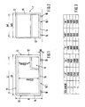
- Figures 1 and 2 show a framework 1 for a housing according to a first embodiment of the present invention.
- the framework 1 shown may consist, for example, of plastic and comprises four vertical members 11, 12, 13 and 14 which are arranged on the side edges of an imaginary cuboid, are of the same length, are located perpendicularly with respect to a base unit 15 of the framework 1 and are fastened on the base unit 15, e.g. by screwed connection.
- the base unit 15 may consist of metal, e.g. aluminium, or of plastic and may comprise, for example, a continuous, single-piece and rectangular base panel or a single-piece base frame of rectangular outline and a base panel arranged on the base frame.
- the base frame may be made up of appropriate longitudinal and transverse members, as individual elements which are fastened to one another, and to consist of plastic.
- rollers 16 Fastened on an underside 15.1 of the base unit 15 of the framework 1 are four rollers 16, which provide the framework 1, and thus the housing or the freezer cabinet as a whole, with the necessary mobility.
- the rollers 16 are fastened on the base unit 15 such that, when the housing is in the ready-installed state, they can no longer be seen, or are concealed, when the viewer is in a standing position. They are thus set back to a sufficient extent from the rectangular outline of the base unit 15.
- top frame 17 Opposite the base unit 15, the vertical members 11, 12, 13 and 14 are fastened at the ends on a top frame 17 which runs all the way round and has essentially a rectangular outer boundary and likewise a rectangular inner boundary.
- the top frame 17 may be designed from plastic as a single-piece frame or may be made up of individual longitudinal and transverse members and webs and have an attachable casing.
- the rectangular top frame 17 is rounded in the corner regions.
- the longitudinal and transverse edges of the top frame 17 which are oriented upwards away from the housing are also rounded.
- the display of a digital thermometer 18 (see Figure 4) for indicating the temperature inside the freezer cabinet is fitted on the top frame 17.
- the top frame 17 is provided with two guides 17.4 one above the other (see Figure 9), which may be designed, for example, as sunken grooves.
- the guides 17.4 guide covers 30 and 31 which are inserted into them and may be displaced in order to render the interior of the housing or of the freezer cabinet accessible, via an access opening 17.3 of the top frame 17, for the purpose of removing or storing the frozen items, or in order to close the same.
- the covers 30 and 31 of the cover arrangement 33 may comprise rectangular, transparent glass panels or plastic panels of the same size or may consist of an opaque or non-transparent material.
- the otherwise exposed edge of the top cover 31 is enclosed by an insulation web 32, which moves along with the cover 31 and is positioned on the cover 30 located therebeneath.
- the plastic insulation web 32 also seals the slit between the two covers 30 and 31 in the closed state of the freezer cabinet.
- a compartment or chamber 19 which serves for accommodating the conventional freezing equipment and units (not shown).
- the conventional interior fittings of the housing are not shown.
- the housing according to the invention also comprises a relatively large-surface-area front-wall panel 20 which is arranged on the front side of the housing and may comprise, for example, a sheet-steel panel or sheet-metal panel, e.g. an aluminium panel.
- the front-wall panel 20 may be provided with a company logo or with an illustration of the types of ice-cream available or a similar illustration.
- the front-wall panel 20 may be fastened, or screwed, for example on retaining means designed for this purpose (not shown), e.g.
- the front-wall panel 20 occupies essentially the entire front side of the housing.
- a rear-wall panel 21 Opposite the front-wall panel 20, there is arranged on the rear side of the housing, that is to say in the region between the vertical members 12 and 14 (not shown), a rear-wall panel 21 (see Figure 11), which may be of identical design to the front-wall panel 20, but is not usually provided with illustrations since it is mostly arranged against the wall of a room when the freezer cabinet has been set up at its location of use.
- the rear-wall panel 21 may be fastened on corresponding retaining means or fastening surfaces on the framework 1.
- the side panels 22 and 23 are of identical dimensions, but only occupy the top section on the sides of the housing. They are produced from metal, e.g. sheet steel, aluminium, etc., and are fastened, e.g. by screwed connection or in the same way as the front-wall panel 20, on correspondingly designed retaining means or fastening surfaces provided on the vertical members 11, 12 and 13, 14 and/or on the top frame 17.
- the outsides of the side panels 22 and 23 may be provided with the abovementioned illustrations.
- side-part arrangements which preferably consist of plastic, are designed as side parts 24 and 25 of the same shape and dimensions (see also Figure 10) and are each essentially in one piece.
- Each of these side parts 24 and 25 is of essentially rectangular outline, as can be seen clearly from Figure 10.
- the side part 24 has an opening 26, which exposes, and renders visible, the side panel 22.
- the outline of the opening 26 is smaller than the outline of the side panel 22, in order that slits between the framework 1 and the side panel 22 which are unavoidable, for example for tolerance reasons, can be reliably covered when the side part 24 is fastened on the framework 1.
- the side part 24 (and also the side part 25) extends from the side region of the housing, by way of corner pieces 27, 28, to the front side of the housing, and thus also covers, in particular, the adjoining corner regions of the front-wall panel 20 when the side part 24 is attached to the framework 1.
- the vertical edges of the side parts 24 and 25 are rounded and constitute the visible vertical edges of the housing.
- the side part 24 (and also the side part 25) has a plurality of mutually parallel ventilation slits 29, which serve for discharging the waste heat produced during cooling.
- the ventilation slits 29 may also be formed in a cover which can be inserted into the side part 24 or may be articulated thereon, for example with swing action.
- a handle 24.12 is formed on each of the side parts 24 and 25.
- a latching and self-retaining spring/counterspring system (not shown).
- a spring or catch snaps into an elastic counterspring or clamp, which secures the latched-in spring.
- a plurality of catches may be provided, for example, on the side part 24 (and also on the side part 25), which, when the side part 24 is fastened on the framework 1, snap or latch into corresponding countersprings on the vertical members 11 and 12.
- the top frame 17, the side parts 24 and 25 and the base unit 15 are designed such that, when the housing is in the assembled state, the surfaces of these components which can be seen from the outside are in alignment with one another.
- plastics which may be used for the plastic parts in use, for example top frame, side-part arrangements, framework, etc., are polyamides, polyacetal resins, polycarbonates, polyphenylene ether, polyolefins, styrene/butadiene copolymers, etc.
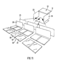
- FIG 11 shows schematically how housings, of the present invention, according to the embodiment of Figures 1 to 3 can be constructed with different volumes (e.g. three different volumes in Figure 11) using standardized and modular components.
- the basis for the modular construction is that the side parts 24 and 25, and also the side parts 22 and 23, are at least of the same shape and dimensions for all the volumes of the housing type.
- Top frame 17, base unit 15, front-wall panel 20, rear-wall panel 21 and the cover arrangement 33 with the covers 30 and 31 are adapted to the different volumes of the housing in terms of their length dimensions.
- the dimensions of the outline of the side parts 24 and 25, which are fixed for all volumes are approximately 810 mm x 650 mm (without the height of the rollers 16).
- the length dimensions of the top frame 17, base unit 15 (base panel), front-wall panel 20, rear-wall panel 21 and cover arrangement 33 are approximately 530 mm to 680 mm for a first volume, approximately 900 mm to 1050 mm for a second volume, approximately 1100 mm to 1250 mm for a third volume and approximately 1350 mm to 1500 mm for a fourth volume. In this respect, you are referred to the self-explanatory table of dimensions of Figure 3.
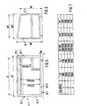
- FIGS 5 and 6 show a framework 1.1 according to a second embodiment of the invention, in the case of which parts which are the same as, or similar to, those in the abovementioned, first embodiment are made of the same materials.
- the framework 1.1 shown comprises, in the same way as the framework 1 of the first embodiment, four vertical members 11.1, 12.1, 13.1 and 14.1 which are arranged on the side edges of an imaginary cuboid, are provided perpendicularly with respect to a base unit 15.11 of the framework 1.1 and are fastened on the base unit 15.11, e.g. by screwed connection.
- the base unit 15.11 is constructed in the same way as the framework 1 of the first embodiment.
- the rear vertical members 12.1 and 14.1 are of the same length, but are longer than the front vertical members 11.1 and 13.1, which are of the same length as each other.
- the vertical members 11.1, 12.1, 13.1 and 14.1 are fastened at the ends on a top frame 17.1 which runs all the way round but, unlike the first embodiment of the present invention, runs with the framework 1.1 at this point, as can be seen clearly from Figure 6, in a plane which is oblique or inclined with respect to the plane of the base unit 15.11, and in this respect the top frame 17.1 is designed differently from the top frame 17 of the framework 1.
- the top frame 17.1 is provided, once again, with two guides 17.4 one above the other, which may be designed, for example, as sunken grooves into which it is possible to insert corresponding covers 30.1 and 31.1, which may be.curved (see Figures 8 and 12), of a cover arrangement 33.1.
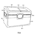
- the housing of the second embodiment similarly to the housing of the first embodiment, comprises a metallic, large-surface-area front-wall panel 20.1 which is arranged on the front side of the housing and, in turn, may be fastened, for example screwed, for example on retaining means provided for this purpose (not shown) on the vertical members 11.1 and 13.1 and/or on the top frame 17.1 and the base unit 15.11, it being possible for the front-wall panel 20.1 to be fastened, preferably in the region of its corners, on the retaining means or fastening surfaces arranged correspondingly on the framework 1.1.
- a metallic rear-wall panel 21.1 Opposite the front-wall panel 20.1, there is arranged on the rear side of the housing, that is to say in the region between the vertical members 12.1 and 14.1, a metallic rear-wall panel 21.1, which nevertheless, in the case of the second embodiment, is of a greater vertical dimension than the front-wall panel 20.1.
- the side panels 22.1 and 23.1 are of identical dimensions, but are only located in the region of the top section on the sides of the housing. They may be of sheet steel and are fastened, e.g. by screwed connection or in the same way as in the first embodiment, on correspondingly designed retaining means or fastening surfaces provided on the vertical members 11.1, 12.1 and 13.1, 14.1 and/or on the top frame 17.1.
- side parts 24.1 and 25.1 which are identical in terms of outline and are each essentially in one piece.
- the side parts 24.1 and 25.1 are adapted, in terms of outline, to the top frame 17.1, which slopes down obliquely from the rear side to the front side, and they thus have an essentially oblique-angled top edge.
- the side parts 24.1 and 25.1 may be fitted on the framework 1.1 as in the case of the first embodiment.
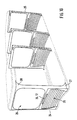
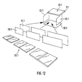
- Figure 12 shows schematically how housings, of the present invention, for the housing type of the second embodiment, of Figures 5 to 8, can be constructed with different volumes (e.g. three different volumes in Figure 12) using standardized and modular components.
- the basis for the modular construction is that the side parts 24.1 and 25.1 are at least of identical outline for all the volumes.
- Top frame 17.1, base unit 15.11, front-wall panel 20.1, rear-wall panel 21.1 and the cover arrangement 33.1 are adapted to the different volumes of the housings in terms of their length dimensions.
- Figure 9 shows a third embodiment of the inventive housing for a freezer cabinet, said housing having a base unit 15.2 which comprises a continuous, single-piece and essentially rectangular base panel. Fastened on the underside of the base panel of the base unit 15.2 are four rollers (not shown).
- a top frame 17.2 which has essentially a rectangular outer boundary and likewise a rectangular inner boundary.
- the top frame 17.2 is designed from plastic as a single-piece frame.
- the rectangular top frame 17.2 is rounded in the corner regions.
- the longitudinal and transverse edges of the top frame 17.2 which are oriented upwards away from the housing are also rounded.
- the display of a digital thermometer 18 is integrated in the top frame 17.2.
- the top frame 17.2 is provided with two guides 17.4 one above the other, which, as in the case of the first embodiment, serve for guiding covers 30.2 and 31.2 inserted therein.
- side parts 24.2 and 25.2 which are at least of the same shape and dimensions, or are identical, and are each essentially in one piece.
- Each of these side parts 24.2 and 25.2 is of essentially rectangular outline.
- the side part 24.2 has an opening 26.2, through which a side panel (not shown in Figure 9) is visible.
- the outline of the opening 26.2 is smaller than the outline of the side panel.
- the side part 24.2 (and also the side part 25.2) extends from the side region of the housing around the vertical edges, by way of corner pieces 27.2, 28.2, to the front side of the housing, and thus also covers, in particular, the adjoining cover regions of a front-wall panel (not shown), which is constructed as in the first embodiment of the invention.
- the side part 24.2 (and also the side part 25.2) have a plurality of mutually parallel ventilation slits 29.2.
- the ventilation slits 29.2 may also be formed in a cover which can be inserted into the side part 24.2 or may be articulated thereon, for example with swing action.
- a handle 24.12 is formed in each case on the side parts 24.2 and 25.2.
- the side parts 24.2 and 25.2 are fastened on the top frame 17.2 and the base unit 15.2 by fastening means (not shown), e.g. by means of a corresponding screwed connection.
- the side parts 24.2 and 25.2 combine the supporting and carrying functions of the vertical members 11, 12, 13 and 14 and the function of the side parts 24 and 25 of the first embodiment of the present invention and, accordingly, are of stable design.
- the top frame 17.2, the side parts 24.2 and 25.2 and the base unit 15.2 are designed such that, when the housing is in the assembled state, the surfaces of these components which can be seen from the outside are in alignment with one another.
- the front-wall panel and also the rear-wall panel may be fastened, for example screwed, for example on retaining means designed for this purpose (not shown) or fastening surfaces on the side parts 24.2 and 25.2 and/or on the top frame 17.2 and the base unit 15.2, the front-wall panel being fastened, preferably in the region of the cornerpieces 27.2 and 28.2 of the side parts 24.2 and 25.2, on these cornerpieces.
- the housing of the third embodiment looks the same as the housing in Figure 4. What has been said above in relation to Figure 11 and the table of dimensions of Figure 3 in conjunction with the first embodiment can also be applied to the modularity and the dimensions of the housings of the third embodiment of the invention.
Description
- Figure 1
- shows a front view of the framework of a first embodiment of the present invention, for a first housing type;
- Figure 2
- shows a side view of the framework of Figure 1;
- Figure 3
- shows a self-explanatory table of dimensions for the embodiment of Figures 1 and 2 in relation to various volumes;
- Figure 4
- shows a ready-assembled housing of the present invention with the framework of Figures 1 and 2;
- Figure 5
- shows a front view of the framework of a second embodiment of the present invention, for a second housing type;
- Figure 6
- shows a side view of the framework of Figure 5;
- Figure 7
- shows a self-explanatory table of dimensions for the second embodiment, shown in Figures 5 and 6, in relation to various volumes;
- Figure 8
- shows a ready-assembled housing of the present invention with the framework of Figures 5 and 6;
- Figure 9
- shows a perspective view of the third embodiment of the present invention (without side panels or front-wall panel);
- Figure 10
- shows a schematic illustration of the side-part arrangements together for the purpose of illustrating the mutual positioning of the side-part arrangements in the case of the first embodiment, shown in Figures 1 and 2;
- Figure 11
- shows a schematic illustration of those modular components together which belong to the first embodiment of the present invention, in accordance with Figures 1 to 3; and
- Figure 12
- shows a schematic illustration of those modular components together which belong to the second embodiment of the present invention, in accordance with Figures 5 and 6.
Claims (23)
- Housing for a freezer installation, in particular a freezer cabinet, for storing frozen foodstuffs, the housing comprising the following modular components:a base unit (15; 15.11; 15.2) of rectangular outline,a top frame (17; 17.1, 17.2) which consists of plastic, is rectangular, runs all the way round, is located opposite the base unit, encloses an access opening (17.3) and bears a movable cover arrangement (33; 33.1; 33.2) which closes or releases the access opening of the top frame,two mutually opposite side-part arrangements which are provided laterally on the housing, of essentially the same outline, extend from the base unit to the top frame of the housing and each have an opening (26; 26.2),side panels (22, 23; 22.1, 23.1) which consist of metal, of which each is arranged on one side of the housing and of which the surfaces are visible through the openings in the side-part arrangements,a rear-wall panel (21; 21.1) which is situated on a rear side of the housing, consists of metal and extends between the side-part arrangements and from the top frame to the base unit, anda front-wall panel (20; 20.1) which is situated on a front side of the housing, consists of metal, is located opposite the rear-wall panel and extends between the side-part arrangements and from the top frame to the base unit, it being the case that the side-part arrangements, the base unit, the top frame with cover arrangement, the front-wall panel and the rear-wall panel bound a housing volume.
- Housing according to Claim 1, characterized in that the side-part arrangements extend, by way of at least one section, into the region of the front side of the housing.
- Housing according to Claim 2, characterized in that the side-part arrangements extend, by way of corner pieces (27, 28; 27.2, 28.2) as sections, to the front side of the housing in the region of the corners of the front-wall panel (20; 20.1).
- Housing according to one of Claims 1 to 3, characterized in that the housing has a framework (1; 1.1), on which the side-part arrangements, the front-wall panel, the rear-wall panel and the side panels are fastened.
- Housing according to Claim 4, characterized in that the framework (1; 1.1) has four vertical members (11, 12, 13, 14; 11.1, 12.1, 13.1, 14.1) which extend between the base unit (15; 15.11) and the top frame (17; 17.1), perpendicularly with respect to a plane of the base unit.
- Housing according to Claim 5, characterized in that the vertical members are of the same length.
- Housing according to Claim 5, characterized in that the vertical members (12.1, 14.1) on the rear side of the housing are longer than the vertical members (11.1, 13.1) on the front side of the housing.
- Housing according to at least one of Claims 4 to 7, characterized in that the framework (1; 1.1) consists of plastic.
- Housing according to at least one of Claims 1 to 8, characterized in that rollers (16; 16.1) are fastened on the underside of the base unit (15; 15.11; 15.2).
- Housing according to at least one of Claims 1 to 9, characterized in that each of the side-part arrangements is designed as a single-piece side part (24, 25; 24.1, 25.1; 24.2, 25.2).
- Housing according to at least one of Claims 1 to 10, characterized in that the side-part arrangements have ventilation slits (29).
- Housing according to one of Claims 1 to 11, characterized in that each of the side-part arrangements has a handle (24.12).
- Housing according to at least one of Claims 1 to 12, characterized in that the front-wall panel and/or the side panels are retained or fastened on the side-part arrangements.
- Modular housing system for housings of different volumes, each housing being provided for a freezer installation, in particular a freezer cabinet, for storing frozen foodstuffs, each housing being of a modular construction and comprising the following components:a base unit (15; 15.11; 15.2) of rectangular outline,a top frame (17; 17.1; 17.2) which consists of plastic, is rectangular, runs all the way round, is located opposite the base unit, encloses an access opening (17.3) and bears a movable cover arrangement (33; 33.1; 33.2) which closes or releases the access opening of the top frame,two mutually opposite side-part arrangements which are provided laterally on the housing and extend from the base unit to the top frame of the housing,a rear-wall panel (21; 21.1) which is situated on a rear side of the housing, consists of metal and extends between the side-part arrangements and from the top frame to the base unit, anda front-wall panel (20; 20.1) which is situated on a front side of the housing, consists of metal, is located opposite the rear-wall panel and extends between the side-part arrangements and from the top frame to the base unit, it being the case that the side-part arrangements, the base unit, the top frame with cover arrangement, the front-wall panel and the rear-wall panel bound a housing volume, and that the side-part arrangements are of the same shape and the same dimensions for all the volumes of the housings at least of one housing type.
- Modular housing system according to Claim 14, characterized in that the housings have a construction according to one of Claims 1 to 13.
- Modular housing system according to Claim 14 or 15, characterized in that, in accordance with the different volumes, the front-wall panels (20; 20.1) are of different length dimensions.
- Modular housing system according to at least one of Claims 14 to 16, characterized in that, in accordance with the different volumes of the housings, the rear-wall panels (21; 21.1) are of different length dimensions.
- Modular housing system according to one of Claims 14 to 17, characterized in that the front-wall panel (20) and the rear-wall panel (21) of a housing are of the same shape and the same dimensions.
- Modular housing system according to at least one of Claims 14 to 18, characterized in that the side-part arrangements (24; 25; 24.1, 25.1) and side panels (22, 23; 22.1, 23.1) are of the same shape and same dimensions for all the housings at least of one housing type.
- Modular housing system according to at least one of Claims 14 to 19, characterized in that, in accordance with the different volumes of the housings, the cover arrangements (33; 33.1; 33.2) are of different length dimensions.
- Modular housing system according to Claim 20, characterized in that the cover arrangement (33) has two panel-like, rectangular covers (30, 31) which are of the same size and, in accordance with the different volumes of the housings, are of different length dimensions and are either transparent or non-transparent.
- Modular housing system according to at least one of Claims 14 to 21, characterized in that the number of volumes is limited.
- Modular housing system according to Claim 22, characterized in that the number of volumes is equal to four.
Applications Claiming Priority (7)
| Application Number | Priority Date | Filing Date | Title |
|---|---|---|---|
| DE29703042 | 1997-02-20 | ||
| DE29703042U | 1997-02-20 | ||
| DE29709654U | 1997-06-03 | ||
| DE29709654 | 1997-06-03 | ||
| DE29711483U | 1997-07-01 | ||
| DE29711483U DE29711483U1 (en) | 1997-02-20 | 1997-07-01 | Cabinet for freezer and cabinet system |
| PCT/EP1998/000769 WO1998037370A1 (en) | 1997-02-20 | 1998-02-11 | Housing for freezer cabinets, and housing system |
Publications (2)
| Publication Number | Publication Date |
|---|---|
| EP0966640A1 EP0966640A1 (en) | 1999-12-29 |
| EP0966640B1 true EP0966640B1 (en) | 2002-06-05 |
Family
ID=27219932
Family Applications (1)
| Application Number | Title | Priority Date | Filing Date |
|---|---|---|---|
| EP98910646A Expired - Lifetime EP0966640B1 (en) | 1997-02-20 | 1998-02-11 | Housing for freezer cabinets, and housing system |
Country Status (6)
| Country | Link |
|---|---|
| US (1) | US6234594B1 (en) |
| EP (1) | EP0966640B1 (en) |
| AU (1) | AU6496198A (en) |
| CA (1) | CA2281502C (en) |
| ES (1) | ES2178177T3 (en) |
| WO (1) | WO1998037370A1 (en) |
Families Citing this family (4)
| Publication number | Priority date | Publication date | Assignee | Title |
|---|---|---|---|---|
| US6800068B1 (en) * | 2001-10-26 | 2004-10-05 | Radiant Medical, Inc. | Intra-aortic balloon counterpulsation with concurrent hypothermia |
| US6617209B1 (en) * | 2002-02-22 | 2003-09-09 | Intel Corporation | Method for making a semiconductor device having a high-k gate dielectric |
| US20080028785A1 (en) * | 2006-08-07 | 2008-02-07 | Kim Brian S | Refrigerator with see-through lid |
| USD1013742S1 (en) * | 2021-10-19 | 2024-02-06 | Lg Electronics Inc. | Refrigerator for vehicles |
Family Cites Families (15)
| Publication number | Priority date | Publication date | Assignee | Title |
|---|---|---|---|---|
| US777895A (en) * | 1904-03-03 | 1904-12-20 | Jacob I Shappiro | Refrigerator. |
| US1387486A (en) * | 1918-05-01 | 1921-08-16 | Walrus Mfg Company | Refrigerator display-case |
| US1896693A (en) * | 1932-07-07 | 1933-02-07 | William De Cou Jr | Refrigerated display device |
| US2598957A (en) * | 1949-02-07 | 1952-06-03 | Dayton Pump & Mfg Co | Panel arrangement for dispensing pumps |
| US2741101A (en) * | 1955-02-28 | 1956-04-10 | True Mfg Co | Cooling cabinet |
| US3729243A (en) | 1971-06-07 | 1973-04-24 | Umc Ind | Merchandising cabinet |
| US4320933A (en) * | 1980-01-15 | 1982-03-23 | Pepsico Inc. | Vending machine with common panel structure |
| US4449761A (en) * | 1981-11-25 | 1984-05-22 | The Coca-Cola Company | Transparent refrigerator doors with frosted product logo thereon |
| JPS60105878A (en) * | 1983-11-15 | 1985-06-11 | 株式会社東芝 | Manufacture of heat-insulating box body |
| DE3513202A1 (en) * | 1985-04-12 | 1986-10-16 | Linde Ag, 6200 Wiesbaden | COOLING FURNITURE |
| GB9219279D0 (en) * | 1992-09-11 | 1992-10-28 | Norfrost Ltd | Improved cabinet |
| US5567026A (en) * | 1994-11-02 | 1996-10-22 | Master-Bilt | Apparatus for displaying products |
| US5752624A (en) * | 1996-07-12 | 1998-05-19 | The Coca-Cola Company | Adjustable fountain dispenser merchandising system |
| DE29716713U1 (en) | 1997-09-17 | 1997-11-27 | Schoeller Lebensmittel | Freezer for storing frozen goods |
| US6012790A (en) * | 1997-10-14 | 2000-01-11 | Steere Enterprises, Inc. | Collapsible, multi-functional kiosk |
-
1998
- 1998-02-11 AU AU64961/98A patent/AU6496198A/en not_active Abandoned
- 1998-02-11 US US09/367,707 patent/US6234594B1/en not_active Expired - Fee Related
- 1998-02-11 WO PCT/EP1998/000769 patent/WO1998037370A1/en active IP Right Grant
- 1998-02-11 EP EP98910646A patent/EP0966640B1/en not_active Expired - Lifetime
- 1998-02-11 CA CA002281502A patent/CA2281502C/en not_active Expired - Fee Related
- 1998-02-11 ES ES98910646T patent/ES2178177T3/en not_active Expired - Lifetime
Also Published As
| Publication number | Publication date |
|---|---|
| CA2281502C (en) | 2006-05-09 |
| WO1998037370A1 (en) | 1998-08-27 |
| US6234594B1 (en) | 2001-05-22 |
| ES2178177T3 (en) | 2002-12-16 |
| CA2281502A1 (en) | 1998-08-27 |
| EP0966640A1 (en) | 1999-12-29 |
| AU6496198A (en) | 1998-09-09 |
Similar Documents
| Publication | Publication Date | Title |
|---|---|---|
| EP1756491B1 (en) | Vacuum storage compartment construction in cooling apparatus | |
| US8132871B1 (en) | Storage system | |
| EP1170561B1 (en) | Method for producing multi-compartment refrigerators | |
| US20020140329A1 (en) | Extractable rack for cabinets equipped with protection bearing cover for slide guides | |
| EP0966640B1 (en) | Housing for freezer cabinets, and housing system | |
| EP3822563A1 (en) | Refrigerator | |
| GB2159616A (en) | Storage cabinet | |
| RU2426043C2 (en) | Refrigerating device designed to store bottles | |
| US4095860A (en) | Storage system | |
| US7162885B2 (en) | Showcase | |
| WO1998004876A1 (en) | Cabinet kit for refrigerator and/or freezer | |
| US20050115286A1 (en) | Showcase | |
| US5662394A (en) | Low-temperature showcase | |
| JP3048855B2 (en) | Open showcase with prefabricated cooling storage | |
| CN111664623B (en) | Domestic refrigeration device with a drawer | |
| JP3756057B2 (en) | Vending machine insulation partition plate | |
| JPH0972649A (en) | Low temperature showcase | |
| JP3735463B2 (en) | Piping structure of storage | |
| KR200275391Y1 (en) | A collecting box for preventing of sliding of collected product | |
| GB2200980A (en) | Domestic refrigerator and/or freezer appliance with closable back wall | |
| JPH0452633Y2 (en) | ||
| JPH05126462A (en) | Cooling/storing device | |
| JP3106905U (en) | Assembled cooktop | |
| JP3048967U (en) | Showcase | |
| JP5565239B2 (en) | vending machine |
Legal Events
| Date | Code | Title | Description |
|---|---|---|---|
| PUAI | Public reference made under article 153(3) epc to a published international application that has entered the european phase |
Free format text: ORIGINAL CODE: 0009012 |
|
| 17P | Request for examination filed |
Effective date: 19990817 |
|
| AK | Designated contracting states |
Kind code of ref document: A1 Designated state(s): DE ES FR GB IT NL SE |
|
| 17Q | First examination report despatched |
Effective date: 20010423 |
|
| GRAG | Despatch of communication of intention to grant |
Free format text: ORIGINAL CODE: EPIDOS AGRA |
|
| GRAG | Despatch of communication of intention to grant |
Free format text: ORIGINAL CODE: EPIDOS AGRA |
|
| GRAH | Despatch of communication of intention to grant a patent |
Free format text: ORIGINAL CODE: EPIDOS IGRA |
|
| GRAH | Despatch of communication of intention to grant a patent |
Free format text: ORIGINAL CODE: EPIDOS IGRA |
|
| GRAA | (expected) grant |
Free format text: ORIGINAL CODE: 0009210 |
|
| AK | Designated contracting states |
Kind code of ref document: B1 Designated state(s): DE ES FR GB IT NL SE |
|
| REG | Reference to a national code |
Ref country code: GB Ref legal event code: FG4D |
|
| REF | Corresponds to: |
Ref document number: 69805770 Country of ref document: DE Date of ref document: 20020711 |
|
| ET | Fr: translation filed | ||
| REG | Reference to a national code |
Ref country code: ES Ref legal event code: FG2A Ref document number: 2178177 Country of ref document: ES Kind code of ref document: T3 |
|
| PLBE | No opposition filed within time limit |
Free format text: ORIGINAL CODE: 0009261 |
|
| STAA | Information on the status of an ep patent application or granted ep patent |
Free format text: STATUS: NO OPPOSITION FILED WITHIN TIME LIMIT |
|
| 26N | No opposition filed |
Effective date: 20030306 |
|
| PG25 | Lapsed in a contracting state [announced via postgrant information from national office to epo] |
Ref country code: IT Free format text: LAPSE BECAUSE OF NON-PAYMENT OF DUE FEES Effective date: 20080211 |
|
| REG | Reference to a national code |
Ref country code: FR Ref legal event code: PLFP Year of fee payment: 19 |
|
| REG | Reference to a national code |
Ref country code: FR Ref legal event code: PLFP Year of fee payment: 20 |
|
| PGFP | Annual fee paid to national office [announced via postgrant information from national office to epo] |
Ref country code: DE Payment date: 20170217 Year of fee payment: 20 Ref country code: SE Payment date: 20170216 Year of fee payment: 20 Ref country code: FR Payment date: 20170217 Year of fee payment: 20 |
|
| PGFP | Annual fee paid to national office [announced via postgrant information from national office to epo] |
Ref country code: GB Payment date: 20170216 Year of fee payment: 20 Ref country code: NL Payment date: 20170216 Year of fee payment: 20 |
|
| PGFP | Annual fee paid to national office [announced via postgrant information from national office to epo] |
Ref country code: IT Payment date: 20170221 Year of fee payment: 20 Ref country code: ES Payment date: 20170213 Year of fee payment: 20 |
|
| REG | Reference to a national code |
Ref country code: DE Ref legal event code: R071 Ref document number: 69805770 Country of ref document: DE |
|
| REG | Reference to a national code |
Ref country code: NL Ref legal event code: MK Effective date: 20180210 |
|
| REG | Reference to a national code |
Ref country code: GB Ref legal event code: PE20 Expiry date: 20180210 |
|
| PG25 | Lapsed in a contracting state [announced via postgrant information from national office to epo] |
Ref country code: GB Free format text: LAPSE BECAUSE OF EXPIRATION OF PROTECTION Effective date: 20180210 |
|
| REG | Reference to a national code |
Ref country code: ES Ref legal event code: FD2A Effective date: 20180525 |
|
| PG25 | Lapsed in a contracting state [announced via postgrant information from national office to epo] |
Ref country code: ES Free format text: LAPSE BECAUSE OF EXPIRATION OF PROTECTION Effective date: 20180212 |