EP0903547B1 - Tiefkühlgerät zur Bevorratung von Tiefkühlgut, insbesondere von abgepackten lebensmitteln wie Speiseeis - Google Patents
Tiefkühlgerät zur Bevorratung von Tiefkühlgut, insbesondere von abgepackten lebensmitteln wie Speiseeis Download PDFInfo
- Publication number
- EP0903547B1 EP0903547B1 EP98117476A EP98117476A EP0903547B1 EP 0903547 B1 EP0903547 B1 EP 0903547B1 EP 98117476 A EP98117476 A EP 98117476A EP 98117476 A EP98117476 A EP 98117476A EP 0903547 B1 EP0903547 B1 EP 0903547B1
- Authority
- EP
- European Patent Office
- Prior art keywords
- freezer
- lid
- container
- freezer according
- service side
- Prior art date
- Legal status (The legal status is an assumption and is not a legal conclusion. Google has not performed a legal analysis and makes no representation as to the accuracy of the status listed.)
- Expired - Lifetime
Links
- 238000007710 freezing Methods 0.000 title claims 12
- 230000008014 freezing Effects 0.000 title claims 12
- 235000015243 ice cream Nutrition 0.000 title claims 2
- 239000002826 coolant Substances 0.000 claims abstract description 9
- 238000001816 cooling Methods 0.000 claims abstract description 3
- 235000013305 food Nutrition 0.000 claims abstract 2
- 239000004020 conductor Substances 0.000 abstract 1
- 235000013611 frozen food Nutrition 0.000 description 2
- 230000002093 peripheral effect Effects 0.000 description 2
- 230000006978 adaptation Effects 0.000 description 1
- 230000001419 dependent effect Effects 0.000 description 1
- 230000002349 favourable effect Effects 0.000 description 1
- 239000011521 glass Substances 0.000 description 1
- 238000009434 installation Methods 0.000 description 1
- 238000009413 insulation Methods 0.000 description 1
- 238000004519 manufacturing process Methods 0.000 description 1
- 230000001737 promoting effect Effects 0.000 description 1
- 239000012780 transparent material Substances 0.000 description 1
Images

Classifications
-
- A—HUMAN NECESSITIES
- A47—FURNITURE; DOMESTIC ARTICLES OR APPLIANCES; COFFEE MILLS; SPICE MILLS; SUCTION CLEANERS IN GENERAL
- A47F—SPECIAL FURNITURE, FITTINGS, OR ACCESSORIES FOR SHOPS, STOREHOUSES, BARS, RESTAURANTS OR THE LIKE; PAYING COUNTERS
- A47F3/00—Show cases or show cabinets
- A47F3/04—Show cases or show cabinets air-conditioned, refrigerated
- A47F3/0404—Cases or cabinets of the closed type
- A47F3/0426—Details
- A47F3/043—Doors, covers
-
- F—MECHANICAL ENGINEERING; LIGHTING; HEATING; WEAPONS; BLASTING
- F25—REFRIGERATION OR COOLING; COMBINED HEATING AND REFRIGERATION SYSTEMS; HEAT PUMP SYSTEMS; MANUFACTURE OR STORAGE OF ICE; LIQUEFACTION SOLIDIFICATION OF GASES
- F25D—REFRIGERATORS; COLD ROOMS; ICE-BOXES; COOLING OR FREEZING APPARATUS NOT OTHERWISE PROVIDED FOR
- F25D15/00—Devices not covered by group F25D11/00 or F25D13/00, e.g. non-self-contained movable devices
-
- F—MECHANICAL ENGINEERING; LIGHTING; HEATING; WEAPONS; BLASTING
- F25—REFRIGERATION OR COOLING; COMBINED HEATING AND REFRIGERATION SYSTEMS; HEAT PUMP SYSTEMS; MANUFACTURE OR STORAGE OF ICE; LIQUEFACTION SOLIDIFICATION OF GASES
- F25D—REFRIGERATORS; COLD ROOMS; ICE-BOXES; COOLING OR FREEZING APPARATUS NOT OTHERWISE PROVIDED FOR
- F25D2400/00—General features of, or devices for refrigerators, cold rooms, ice-boxes, or for cooling or freezing apparatus not covered by any other subclass
- F25D2400/10—Refrigerator top-coolers
-
- F—MECHANICAL ENGINEERING; LIGHTING; HEATING; WEAPONS; BLASTING
- F25—REFRIGERATION OR COOLING; COMBINED HEATING AND REFRIGERATION SYSTEMS; HEAT PUMP SYSTEMS; MANUFACTURE OR STORAGE OF ICE; LIQUEFACTION SOLIDIFICATION OF GASES
- F25D—REFRIGERATORS; COLD ROOMS; ICE-BOXES; COOLING OR FREEZING APPARATUS NOT OTHERWISE PROVIDED FOR
- F25D2400/00—General features of, or devices for refrigerators, cold rooms, ice-boxes, or for cooling or freezing apparatus not covered by any other subclass
- F25D2400/38—Refrigerating devices characterised by wheels
-
- F—MECHANICAL ENGINEERING; LIGHTING; HEATING; WEAPONS; BLASTING
- F25—REFRIGERATION OR COOLING; COMBINED HEATING AND REFRIGERATION SYSTEMS; HEAT PUMP SYSTEMS; MANUFACTURE OR STORAGE OF ICE; LIQUEFACTION SOLIDIFICATION OF GASES
- F25D—REFRIGERATORS; COLD ROOMS; ICE-BOXES; COOLING OR FREEZING APPARATUS NOT OTHERWISE PROVIDED FOR
- F25D2500/00—Problems to be solved
- F25D2500/02—Geometry problems
Definitions
- the invention relates to a freezer after the Preamble of claim 1.
- a freezer of this type is known from WO-A-96/38074 known as a so-called counter top attachment.
- the freezer container cuboid housing with a horizontal top on, at the front of the freezer moves the removal opening in a horizontal position is positioned.
- the back of the Freezer container, from which the removal opening to the front is offset there is a Tiefkühl coupled with a freezer.
- This freezer is designed to meet the need for a handy Freezer with a relatively small Cover freezer, and it should therefore from relatively small size and as small as possible Be weight to it for z. B. on sales counters for Presentation of relatively small quantities of To put up frozen goods.
- the known freezer has a considerable Weight, which makes its installation on small and tight Stands is difficult.
- the invention is based on the object Freezer of the type described above so to design that while ensuring a good Handling an improved insight into the Freezer is reached.
- the main parts of the generally designated 1 in Fig. 1 freezer are a heat-insulated freezer 2 with an interior or receiving space 3 for Frozen food, which can be opened by an optional opening and closing Access or removal opening 4 is accessible and a Tiefkühl responded with a Deep-freeze unit 5, which by suggestively illustrated, flexible coolant lines. 6 with at least one freezer body (not shown) arranged in the receiving space 3 connected is.
- the freezer 1 may be mounted on a carrier, for. As a counter, a table or a cupboard. Due to the presence of flexible Coolant lines 6 consists in a through the length of the coolant lines. 6 given area a limited independence between the freezer 2 and the freezer 5, so that in this area of the freezer 2 independent can be adjusted and positioned by the freezer 5, z. B. in a position in he is particularly favorable visible.
- the freezer 5 can be in by the length the coolant lines 6 predetermined range independent of the freezer container. 2 be placed, for. B. under the freezer container 2 supporting carrier.
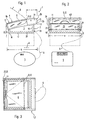
- the upper side of the deep-freeze container 2 is inclined toward the front or operating side 7, where it can be flat or slightly curved, preferably convex curved, such as it can be seen in the side view of FIG. 1.
- the removal opening 4 is through a Cover 8 optional to open and close. It can be a hinged lid act around a preferably extending at its rear edge hinge axis. 9 is pivotally mounted. It is also possible to form the cover 8 as a sliding cover, which is slidable during the opening movement in a free space of the freezer container.
- the removal opening 4 extends substantially over the entire, parallel to the operating side 7 extending length a of Freezer container 2 and only over part of the width b of the freezer container 2, where you front edge 11 is located on the operating side and its rear edge 12 a distance c from the back 13 of the cooling container 2 has.
- This is between the rear Edge 12 and the back 13, a free space 14 available, in which a sliding cover is insertable. It can realize a small size for the space 14, if in the space 14, a U-shaped guide 15 is provided for a lid 8, the arranged parallel to the operating side 7 and hinged together Slats consists, so that such a shutter-shaped lid in the U-shaped guide 15 is inserted.
- a handle part 8a is arranged on the cover 8, where the lid 8 can be gripped and moved handling friendly.
- the lid 8 can be gripped and moved handling friendly.
- This is at open removal opening 4 a good view into the receiving space 3 and thus also on ensures that it contains frozen goods.
- the lid 8 made of transparent Material, such. As glass or plastic, is, this good insight is also at closed removal opening 4 ensures.
- the freezer container 2 consists of a lower, box-shaped container portion 2a and an upper container portion 2b, of which the upper on two opposite sides, here on the left and right side, with respect to the lower container portion 2a is stepped.
- Step surfaces 16 formed which serve as support surfaces for the freezer 2 can, as will be described below.
- the lower container portion 2a has a flat bottom wall 17 and of the latter Peripheral edge on vertically upwardly extending peripheral wall parts, namely a Front wall portion 18, a rear wall portion 19 and in between two side wall portions 21.
- the upper container portion 2b has a front wall portion 22, a Rear wall portion 23 and between two side wall portions 24, of which the latter Side wall parts 21 overlap on the outside, see Fig. 2.
- the side wall parts 24 can be formed by just extending strips. In the present embodiment are the side wall portions 24 with their upper and lower edges corresponding to the above-described rounding of the top by a hinted in Fig. 1 Curvature axis A curved.
- the front wall part 22 is with respect to the axis of curvature A is arranged approximately radially, so that it with respect to the underlying front wall part 18 has a tilted forward tilt.
- the rear wall part 23 is preferably in accordance with the semicircular shutter guide semi-cylindrical curved.
- At least the walls of the lower container portion 2a are thermally insulated, resulting in a suggestively illustrated thermal insulation 26 is characterized. This applies preferably also for the upper container section 2b and for the windows 25a, 25b, the latter can be heat insulating windows, in particular those with a Space between at least two windows.
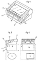
- FIGS. 5 and 6 is a freezer 1 with a Freezer 2 shown
- the lower container portion 2a also higher is dimensioned, and consequently the receiving volume is correspondingly larger.
- the freezer 1 and the freezer 2 on a support 27 arranged in the form of a table or a counter and that in a receiving hole 28 with a size adapted to the cross-sectional size of the lower tank portion 2a, the freezer 2 with its step surfaces 16 on the upper plate 29 or with its bottom wall 17 can rest on a lower plate 31 of the carrier 27.
- the Deep-freeze unit 5 may be positioned under the carrier 27, for. B. under the plate 31st
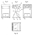
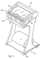
- the freezer 1 is mounted on a carrier 27 arranged in the form of a movable carriage or chassis 33 with wheels 33 a.
- the freezer container 2 with its step surfaces 16 on the upper end faces 35 of opposing side walls 34 of the chassis 33, wherein the upper end faces 35 in adaptation to the shape of the step surfaces 16 flat or may be formed curved accordingly.
- the Freezer 2 positioned laterally between the side walls 34. For positioning against slipping forward and backward, not shown Journal connections or stops are provided, which provide a sliding movement of the Limit freezer 2.
- the upper End faces 35 are inclined forward, it is advantageous in the rear region of the Side wall portions 24 at 36 a lower projection on the upper side wall portions 24th or to arrange a lateral projection on the lower side wall parts 21, which the Behind the side walls 34 in the sense of a stop.
- the side walls 34 can front and back with rounded recesses 37 may be formed, the weight save and improve accessibility.
- the side walls 34 are by a horizontal bottom plate or cross member 38th connected and stabilized, on which the freezer unit 5 may be arranged can.
- the coolant lines 6 are made Simplification reasons not shown.
Landscapes
- Engineering & Computer Science (AREA)
- Physics & Mathematics (AREA)
- Thermal Sciences (AREA)
- Chemical & Material Sciences (AREA)
- Combustion & Propulsion (AREA)
- Mechanical Engineering (AREA)
- General Engineering & Computer Science (AREA)
- Freezing, Cooling And Drying Of Foods (AREA)
- Devices That Are Associated With Refrigeration Equipment (AREA)
- Confectionery (AREA)
Description
- Fig. 1
- ein erfindungsgemäßes Tiefkühlgerät in der Seitenansicht;
- Fig. 2
- das Tiefkühlgerät in der Vorderansicht;
- Fig. 3
- das Tiefkühlgerät in der Draufsicht;
- Fig. 4
- einen Tiefkühlbehälter des Tiefkühlgerätes in perspektivischer Vorderansicht;
- Fig. 5
- ein erfindungsgemäßes Tiefkühlgerät in der Seitenansicht, das auf einem Möbel angeordnet ist.
- Fig. 6
- das Tiefkühlgerät und das Möbel nach Fig. 5 in der Vorderansicht;
- Fig. 7
- ein erfindungsgemäßes Tiefkühlgerät in der Seitenansicht, das auf einem verfahrbaren Möbel angeordnet ist;
- Fig. 8
- das Tiefkühlgerät und das Möbel nach Fig. 7 in der Vorderansicht;
- Fig. 9
- das Tiefkühlgerät und das Möbel nach Fig. 7 in der Rückansicht;
- Fig. 10
- das Tiefkühlgerät und das Möbel nach Fig. 7 in der Draufsicht;
- Fig. 11
- das Tiefkühlgerät und das Möbel nach Fig. 7 in perspektivischer Vorderansicht;
- Fig. 12
- das Möbel nach Fig. 7 in der Vorderansicht;
- Fig. 13
- das Möbel nach Fig. 12 in der Seitenansicht; und
- Fig. 14
- das Möbel nach Fig. 12 in der Draufsicht.
Claims (13)
- Tiefkühlgerät (1) zur Bevorratung von Tiefkühlgut, insbesondere von abgepackten Lebensmitteln wie Speiseeis, mit einem Tiefkühlbehälter (2) mit einem Aufnahmeraum (3) für das Tiefkühlgut, der über zumindest eine mittels eines Deckels (8) verschließbare Entnahmeöffnung (4) von einer Bedienseite (7) her zugänglich ist, und mit einem Tiefkühlaggregat (5) zum Kühlen des Aufnahmeraums(3), wobei das Tiefkühlaggregat (5) von dem Tiefkühlbehälter (2) räumlich getrennt und mit diesem über flexible Kühlmittelleitungen (6) verbunden ist,
dadurch gekennzeichnet, daß der Tiefkühlbehälter (2) aus einem unteren Behälterabschnitt (2a) und einem oberen, den Deckel (8) aufweisenden Behälterabschnitt (2b) besteht, wobei der obere Behälterabschnitt (2b) eine derart zur Bedienseite (7) hin gekippte Schrägstellung aufweist, daß seine Unterkante und der Deckel (8) gegenüber der Horizontalebene in Richtung auf die Bedienseite (7) geneigt angeordnet sind. - Tiefkühlgerät nach Anspruch 1,
dadurch gekennzeichnet, daß der Deckel (8) kleiner bemessen ist, als die Fläche der Oberseite des Tiefkühlbehälters (2) und daß der vom Deckel (8) nicht eingenommene Bereich der Fläche der Oberseite ebenfalls in Richtung auf die Bedienseite geneigt ist. - Tiefkühlgerät nach Anspruch 1 oder 2,
dadurch gekennzeichnet, daß der Deckel (8) und/oder der neben dem Deckel (8) befindliche Flächenbereich der Oberseite um eine sich horizontal und parallel zur Bedienseite (7) erstreckende Krümmungsachse (A) gekrümmt ist. - Tiefkühlgerät nach Anspruch 2 oder 3,
dadurch gekennzeichnet, daß ein der Bedienseite (7) zugewandte Rand (11) der Entnahmeöffnung (4) an der Bedienseite (7) angeordnet ist. - Tiefkühlgerät nach einem der Ansprüche 2 bis 4,
dadurch gekennzeichnet, daß ein der Bedienseite (7) abgewandte Rand (12) der Entnahmeöffnung (4) einen Abstand (c) von der Rückseite (13) des Tiefkühlbehälters (2) aufweist. - Tiefkühlgerät nach einem der vorherigen Ansprüche,
dadurch gekennzeichnet, daß der Deckel (8) ein Klappdeckel ist, dessen horizontale Schwenkachse (9) vorzugsweise parallel zur Bedienseite (7) am hinteren Rand (12) der Entnahmeöffnung (4) angeordnet ist. - Tiefkühlgerät nach einem der Ansprüche 1 bis 5,
dadurch gekennzeichnet, daß der Deckel (8) ein Schiebedeckel ist, der bei seiner Öffnungsbewegung in einen Freiraum (14) schiebbar ist, der auf der der Bedienseite (7) abgewandten Seite des Tiefkühlbehälters (2) angeordnet ist. - Tiefkühlgerät nach einem der vorherigen Ansprüche,
dadurch gekennzeichnet, daß der Tiefkühlbehälter (2) vorzugsweise seitlich einander gegenüberliegende Stufenflächen (16) aufweist, die Stützflächen zum Aufstellen des Tiefkühlbehälters (2) auf einen Träger (27) bilden. - Tiefkühlgerät nach Anspruch 8,
dadurch gekennzeichnet, daß die Stufenflächen (16) einen nach oben gerichteten Abstand von der Unterseite des Tiefkühlbehälters (2) aufweisen. - Tiefkühlgerät nach einem der vorherigen Ansprüche,
dadurch gekennzeichnet, daß der Träger durch einen Tisch oder einen Schrank oder ein Traggestell gebildet ist. - Tiefkühlgerät nach einem der vorherigen Ansprüche,
dadurch gekennzeichnet, daß das Tiefkühlgerät (1) mit einem Träger (27) eine aufstellbare Einheit bildet. - Tiefkühlgerät nach Anspruch 11,
dadurch gekennzeichnet, daß der Träger (27) Räder (33a) aufweist und verfahrbar ist. - Tiefkühlgerät nach einem der vorherigen Ansprüche,
dadurch gekennzeichnet, daß der obere Behälterabschnitt (2b) mit unterschiedlich hohen unteren Behälterabschnitten (2a) verbindbar ist.
Applications Claiming Priority (2)
| Application Number | Priority Date | Filing Date | Title |
|---|---|---|---|
| DE29716711U DE29716711U1 (de) | 1997-09-17 | 1997-09-17 | Tiefkühlgerät zur Bevorratung von Tiefkühlgut, insbesondere von abgepackten Lebensmitteln wie Speiseeis |
| DE29716711U | 1997-09-17 |
Publications (3)
| Publication Number | Publication Date |
|---|---|
| EP0903547A2 EP0903547A2 (de) | 1999-03-24 |
| EP0903547A3 EP0903547A3 (de) | 2000-10-11 |
| EP0903547B1 true EP0903547B1 (de) | 2005-11-16 |
Family
ID=8046128
Family Applications (1)
| Application Number | Title | Priority Date | Filing Date |
|---|---|---|---|
| EP98117476A Expired - Lifetime EP0903547B1 (de) | 1997-09-17 | 1998-09-15 | Tiefkühlgerät zur Bevorratung von Tiefkühlgut, insbesondere von abgepackten lebensmitteln wie Speiseeis |
Country Status (3)
| Country | Link |
|---|---|
| EP (1) | EP0903547B1 (de) |
| AT (1) | ATE310218T1 (de) |
| DE (2) | DE29716711U1 (de) |
Family Cites Families (5)
| Publication number | Priority date | Publication date | Assignee | Title |
|---|---|---|---|---|
| US2319433A (en) * | 1941-04-30 | 1943-05-18 | Robert L Phillips | Store window showcase |
| US2503419A (en) * | 1947-06-27 | 1950-04-11 | John A Secunde | Refrigerator display rack |
| US3729243A (en) * | 1971-06-07 | 1973-04-24 | Umc Ind | Merchandising cabinet |
| DE2622817A1 (de) * | 1976-05-21 | 1977-12-01 | Heinrich Gilbert & Sohn Kg | Kuehl- und verkaufsstand |
| WO1996038074A1 (en) * | 1995-05-31 | 1996-12-05 | Hmg Worldwide In-Store Marketing, Inc. | Shelf mounted refrigerated display unit |
-
1997
- 1997-09-17 DE DE29716711U patent/DE29716711U1/de not_active Expired - Lifetime
-
1998
- 1998-09-15 AT AT98117476T patent/ATE310218T1/de not_active IP Right Cessation
- 1998-09-15 DE DE59813191T patent/DE59813191D1/de not_active Expired - Lifetime
- 1998-09-15 EP EP98117476A patent/EP0903547B1/de not_active Expired - Lifetime
Also Published As
| Publication number | Publication date |
|---|---|
| DE59813191D1 (de) | 2005-12-22 |
| ATE310218T1 (de) | 2005-12-15 |
| EP0903547A2 (de) | 1999-03-24 |
| EP0903547A3 (de) | 2000-10-11 |
| DE29716711U1 (de) | 1997-11-27 |
Similar Documents
| Publication | Publication Date | Title |
|---|---|---|
| DE69315188T2 (de) | Gleitendes, überlaufsicheres Kragarmregal | |
| EP1032796B1 (de) | Kühlgerät | |
| EP0929247B1 (de) | Lagervorrichtung zur weitestgehend liegenden lagerung für flaschenartiges lagergut | |
| EP1984687A2 (de) | Kältegerät mit fachboden | |
| EP0937223B1 (de) | Kühlgerätetür | |
| EP2907951B1 (de) | Gewerbliches Kühlregal | |
| DE19740900C2 (de) | Tiefkühlgerät für Tiefkühlprodukte | |
| EP0903547B1 (de) | Tiefkühlgerät zur Bevorratung von Tiefkühlgut, insbesondere von abgepackten lebensmitteln wie Speiseeis | |
| EP2370764B1 (de) | Kältegerät | |
| EP2512296B1 (de) | Warentheke | |
| DE19740903C2 (de) | Tiefkühltruhe für Tiefkühlgut, insbesondere Tiefkühlkost oder Speiseeis | |
| DE19821823B4 (de) | Kühl- und/oder Gefriergerät mit einem Halter für eine Flasche und/oder eine Dose | |
| EP0648990A1 (de) | Kühlgerät | |
| WO2012130573A2 (de) | Kältegerät | |
| DE102016205992A1 (de) | Kältegerät mit Flaschenhalter | |
| EP0918973B1 (de) | Möbel mit haltevorrichtung zur halterung von liegend angeordnetem flaschenartigem lagergut | |
| EP0728998A1 (de) | Kühlschranktür mit Flaschenabsteller | |
| EP0648988B1 (de) | Kühlschrank mit einschiebbaren Ablagefachböden | |
| EP2059744A1 (de) | Kältegerät mit einem mit schiebetüren verschliessbarem behälter | |
| DE1554624C3 (de) | Ausschanktisch | |
| DE102006049397A1 (de) | Kältegerät mit entnehmbarem Kühlgutträger | |
| DE102004042566A1 (de) | Tür für ein Kältegerät | |
| DE29901687U1 (de) | Warenauslage | |
| EP0067241A1 (de) | Kühltruhe | |
| CH416298A (de) | Ladentisch |
Legal Events
| Date | Code | Title | Description |
|---|---|---|---|
| PUAI | Public reference made under article 153(3) epc to a published international application that has entered the european phase |
Free format text: ORIGINAL CODE: 0009012 |
|
| AK | Designated contracting states |
Kind code of ref document: A2 Designated state(s): AT BE DE DK FR GB LU NL |
|
| AX | Request for extension of the european patent |
Free format text: AL;LT;LV;MK;RO;SI |
|
| PUAL | Search report despatched |
Free format text: ORIGINAL CODE: 0009013 |
|
| AK | Designated contracting states |
Kind code of ref document: A3 Designated state(s): AT BE CH CY DE DK ES FI FR GB GR IE IT LI LU MC NL PT SE |
|
| AX | Request for extension of the european patent |
Free format text: AL;LT;LV;MK;RO;SI |
|
| RIC1 | Information provided on ipc code assigned before grant |
Free format text: 7F 25D 11/04 A, 7A 47F 3/04 B, 7F 25D 23/02 B, 7F 25D 15/00 B |
|
| 17P | Request for examination filed |
Effective date: 20010123 |
|
| AKX | Designation fees paid |
Free format text: AT BE DE DK FR GB LU NL |
|
| 17Q | First examination report despatched |
Effective date: 20030709 |
|
| GRAP | Despatch of communication of intention to grant a patent |
Free format text: ORIGINAL CODE: EPIDOSNIGR1 |
|
| RIN1 | Information on inventor provided before grant (corrected) |
Inventor name: REHKLAU, ANDREAS Inventor name: STAUCH, RUEDIGER Inventor name: NEUMANN, UWE Inventor name: LINDE, HANSJUERGEN, PROF. DR.-ING. Inventor name: KOHLHOFF, CLAUDIA Inventor name: MAUL, ANDREA Inventor name: OCKER, FRANK Inventor name: FAISST, PETER Inventor name: VORNDRAN, THOMAS Inventor name: SCHOPPER, RICHARD Inventor name: GOETTFERT, THOMAS Inventor name: BEER, RICHARD |
|
| RAP1 | Party data changed (applicant data changed or rights of an application transferred) |
Owner name: NESTEC S.A. |
|
| GRAS | Grant fee paid |
Free format text: ORIGINAL CODE: EPIDOSNIGR3 |
|
| GRAA | (expected) grant |
Free format text: ORIGINAL CODE: 0009210 |
|
| AK | Designated contracting states |
Kind code of ref document: B1 Designated state(s): AT BE DE DK FR GB LU NL |
|
| PG25 | Lapsed in a contracting state [announced via postgrant information from national office to epo] |
Ref country code: NL Free format text: LAPSE BECAUSE OF FAILURE TO SUBMIT A TRANSLATION OF THE DESCRIPTION OR TO PAY THE FEE WITHIN THE PRESCRIBED TIME-LIMIT Effective date: 20051116 |
|
| REG | Reference to a national code |
Ref country code: GB Ref legal event code: FG4D Free format text: NOT ENGLISH |
|
| REF | Corresponds to: |
Ref document number: 59813191 Country of ref document: DE Date of ref document: 20051222 Kind code of ref document: P |
|
| PG25 | Lapsed in a contracting state [announced via postgrant information from national office to epo] |
Ref country code: DK Free format text: LAPSE BECAUSE OF FAILURE TO SUBMIT A TRANSLATION OF THE DESCRIPTION OR TO PAY THE FEE WITHIN THE PRESCRIBED TIME-LIMIT Effective date: 20060216 |
|
| GBT | Gb: translation of ep patent filed (gb section 77(6)(a)/1977) |
Effective date: 20060202 |
|
| NLV1 | Nl: lapsed or annulled due to failure to fulfill the requirements of art. 29p and 29m of the patents act | ||
| ET | Fr: translation filed | ||
| PLBE | No opposition filed within time limit |
Free format text: ORIGINAL CODE: 0009261 |
|
| STAA | Information on the status of an ep patent application or granted ep patent |
Free format text: STATUS: NO OPPOSITION FILED WITHIN TIME LIMIT |
|
| PG25 | Lapsed in a contracting state [announced via postgrant information from national office to epo] |
Ref country code: BE Free format text: LAPSE BECAUSE OF NON-PAYMENT OF DUE FEES Effective date: 20060930 |
|
| 26N | No opposition filed |
Effective date: 20060817 |
|
| PG25 | Lapsed in a contracting state [announced via postgrant information from national office to epo] |
Ref country code: AT Free format text: LAPSE BECAUSE OF NON-PAYMENT OF DUE FEES Effective date: 20060915 |
|
| BERE | Be: lapsed |
Owner name: NESTEC S.A. Effective date: 20060930 |
|
| PG25 | Lapsed in a contracting state [announced via postgrant information from national office to epo] |
Ref country code: LU Free format text: LAPSE BECAUSE OF NON-PAYMENT OF DUE FEES Effective date: 20060915 |
|
| PGFP | Annual fee paid to national office [announced via postgrant information from national office to epo] |
Ref country code: GB Payment date: 20090909 Year of fee payment: 12 |
|
| PGFP | Annual fee paid to national office [announced via postgrant information from national office to epo] |
Ref country code: DE Payment date: 20090910 Year of fee payment: 12 |
|
| PGFP | Annual fee paid to national office [announced via postgrant information from national office to epo] |
Ref country code: FR Payment date: 20091012 Year of fee payment: 12 |
|
| GBPC | Gb: european patent ceased through non-payment of renewal fee |
Effective date: 20100915 |
|
| REG | Reference to a national code |
Ref country code: FR Ref legal event code: ST Effective date: 20110531 |
|
| REG | Reference to a national code |
Ref country code: DE Ref legal event code: R119 Ref document number: 59813191 Country of ref document: DE Effective date: 20110401 |
|
| PG25 | Lapsed in a contracting state [announced via postgrant information from national office to epo] |
Ref country code: DE Free format text: LAPSE BECAUSE OF NON-PAYMENT OF DUE FEES Effective date: 20110401 Ref country code: FR Free format text: LAPSE BECAUSE OF NON-PAYMENT OF DUE FEES Effective date: 20100930 |
|
| PG25 | Lapsed in a contracting state [announced via postgrant information from national office to epo] |
Ref country code: GB Free format text: LAPSE BECAUSE OF NON-PAYMENT OF DUE FEES Effective date: 20100915 |