EP0903327A2 - Verfahren zum Scheiden von nichtmetallischen Materialien - Google Patents
Verfahren zum Scheiden von nichtmetallischen Materialien Download PDFInfo
- Publication number
- EP0903327A2 EP0903327A2 EP98117545A EP98117545A EP0903327A2 EP 0903327 A2 EP0903327 A2 EP 0903327A2 EP 98117545 A EP98117545 A EP 98117545A EP 98117545 A EP98117545 A EP 98117545A EP 0903327 A2 EP0903327 A2 EP 0903327A2
- Authority
- EP
- European Patent Office
- Prior art keywords
- crack
- substrate
- metal material
- heating zone
- separating
- Prior art date
- Legal status (The legal status is an assumption and is not a legal conclusion. Google has not performed a legal analysis and makes no representation as to the accuracy of the status listed.)
- Withdrawn
Links
Images


Classifications
-
- C—CHEMISTRY; METALLURGY
- C03—GLASS; MINERAL OR SLAG WOOL
- C03B—MANUFACTURE, SHAPING, OR SUPPLEMENTARY PROCESSES
- C03B33/00—Severing cooled glass
- C03B33/09—Severing cooled glass by thermal shock
-
- B—PERFORMING OPERATIONS; TRANSPORTING
- B23—MACHINE TOOLS; METAL-WORKING NOT OTHERWISE PROVIDED FOR
- B23K—SOLDERING OR UNSOLDERING; WELDING; CLADDING OR PLATING BY SOLDERING OR WELDING; CUTTING BY APPLYING HEAT LOCALLY, e.g. FLAME CUTTING; WORKING BY LASER BEAM
- B23K26/00—Working by laser beam, e.g. welding, cutting or boring
- B23K26/36—Removing material
- B23K26/40—Removing material taking account of the properties of the material involved
-
- B—PERFORMING OPERATIONS; TRANSPORTING
- B23—MACHINE TOOLS; METAL-WORKING NOT OTHERWISE PROVIDED FOR
- B23K—SOLDERING OR UNSOLDERING; WELDING; CLADDING OR PLATING BY SOLDERING OR WELDING; CUTTING BY APPLYING HEAT LOCALLY, e.g. FLAME CUTTING; WORKING BY LASER BEAM
- B23K2103/00—Materials to be soldered, welded or cut
- B23K2103/50—Inorganic materials other than metals or composite materials
Definitions
- the present invention relates to a method for separating a brittle non-metal material such as glass used in an electronic industry utilizing a thermal stress.
- a plurality of patterns is formed on a large and flat glass substrate and is required to be separated individually. Developing a processing technique such that the plurality of patterns can be separated without producing small glass chips and wastes has been desired.
- An example of the separation includes a use of a thermal stress, which is described below referring to Figures.
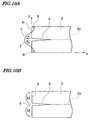
- a glass substrate 2 having a lower melting point and a thickness of about 3 mm is mounted on a supporting stand 1.
- a linear heat source for example a sheath heater 3 having a diameter of 9 mm, a length of 1400 mm and input power of 600 W is disposed in contact with a bottom surface of the glass substrate 2.
- an end face flaw 4 is formed by pointing with diamond.
- temperature of a linear area (heating zone designated by a dashed line) 2a along the sheath heater increases.
- a stress is produced in a y direction in proportion to the stress 7, 8 in an x direction shown in Fig. 10A.
- the stress is concentrated on the end face flaw 4.
- a crack 5 is produced from the end face flaw 4 along the heating zone 2a.
- a stress intensity factor is produced by the moment M as shown in Fig. 10B.
- the value of the stress intensity factor exceeds a fracture toughness value of the glass, the crack 5 further extends.
- a mechanism of the crack extension by the linear heat source is similar to a model subjecting a tensile stress 7 and a compressive stress 8 in an isothermal system as shown in Fig. 10A. Such stress urges the moment to act.
- a method for separating a non-metal material comprising the steps of contacting a substrate made of the non-metal material with a linear heat source to form a heating zone, cooling locally a tip of a crack produced on the heating zone, and extending the crack along the heating zone to separate the substrate.
- a method for separating a non-metal material comprising the steps of contacting a substrate made of the non-metal material with a linear heat source to form a heating zone, extending a crack produced on the material by applying a heat and applying an inverted stress to an end of the substrate so as to dissipate a stress for closing the crack with the crack being approached to the end.
- a method for separating a non-metal material comprising the steps of contacting a substrate made of the non-metal material with a linear heat source to form a heating zone, cooling locally a tip of a crack produced on the heating zone, and applying an inverted stress to an edge of the substrate.
- the linear heat source is contacted with one surface of the substrate, and a cooling medium is sprayed onto the heating zone of the other surface to cool locally.
- the cooling medium may be sprayed onto a contact portion of the substrate and the linear heat source bidirectionally.
- a nozzle for applying the cooling medium may be disposed at a tilt to the substrate to spray backward to the crack.
- a diameter of the local cooled area is 0.5% greater or more of a width of the substrate.
- a portion being subject to separation at the edge of the substrate is fixed and both sides of the portion are held movably in a crack extending direction and a perpendicular direction thereof, thereby applying an inverted stress to the edge of the substrate.
- a portion being subject to separation at the edge of the substrate is fixed and external force is added to both sides of the portion in the crack extending direction, thereby applying an inverted stress to the edge of the substrate.
- a method for separating a non-metal material comprising the steps of contacting a substrate made of the non-metal material with a linear heat source to form a heating zone, cooling locally the heating zone adjacent to one side edge of the substrate opposite to the other side edge having a flaw with a cooling position being fixed, cooling locally a crack produced from the end face flaw on the heating zone, and moving the local cooled area of the crack along the heating zone and extending the crack along the heating zone.
- a method for separating a brittle non-metal material having a wide width such as glass and ceramics utilizing a heat stress is disclosed herein.
- a strip substrate made of the non-metal material is contacted with a linear heat source such as sheath heater to form a heating zone on the substrate, a crack is extended by applying a heat from an end face flaw formed on one side edge of the substrate in advance, an inverted stress is applied to the edge of the substrate so as to dissipate a stress for closing the crack with the crack being approaching to the end, thereby separating the substrate without lowering a crack extending speed to the end of the substrate.
- a tip of the crack slightly extended from the end face flaw by applying a heat is cooled locally at room temperature or less and the cooled area is moved along the heating zone. This allows extending the crack to the end of the substrate at high speed to separate the substrate. It is possible to extend the crack to the end of the substrate readily without lowering the extending speed by using a combination of the local cooling of the tip of the crack and the inverted stress.
- Most preferable cooling area is the tip of the crack and backward thereof.
- the crack is not extended. Therefore, the front area of the tip should not be cooled. Both the tip of the crack and the front area thereof may be cooled, but the front area should be cooled at minimum.
- a size of the cooled area has a lower limit and the lower limit depends on a width W of the substrate.
- a diameter X of the crack in the extending direction is desirably represented by a numerical relation of X/W>0.005. In other words, the diameter of the crack that is 0.5% greater or more of the width of the substrate must be cooled.
- the local cooling Upon the local cooling, it is sufficient to cool a part of the heating zone (the tip of the crack) to room temperature, where has been heated to the predetermined temperature exceeding room temperature. Accordingly, the local cooling corresponds to a local formation of a non-heated area. It may be cooled to room temperature or less. As cooling means, air at room temperature, a mixture of air and water, cooled solid such as metals and ceramics may be contacted with the substrate.
- the local cooling can control and cool an area to be cooled accurately compared to a fluid cooling.
- this allows a great stress intensity factor and a high extending speed of the crack.
- the linear heat source may be contacted with one surface of the substrate to form the heating zone, and the cooling medium may be sprayed from the nozzle on the other surface of the substrate.
- the cooling medium is desirably sprayed with a pair of nozzles disposed at both sides of the linear heat source bidirectionally to a contact portion of the linear heat source and the substrate. According to the bidirectional method, both of the substrate and the linear heat source are spontaneously cooled locally and a thin fluid film is produced between the linear heat source and the substrate to lose thermal conductivity toward the substrate. Therefore, an excellent response of the heat stress and high extending speed of the crack can be advantageously obtained.
- the nozzle may be tilted not to cool the front area of the tip of the crack and to spray the cooling medium backward to the crack.
- the heater Upon contacting the linear heat source, i.e., heater, with the substrate, the heater is supported not to make a non-contact portion between the heater and the substrate. Almost whole heater is supported so as not to lower temperature at the support portion.
- the linear heat source may be curved.
- a substrate composed of a non-metal material such as glass and ceramics is contacted with a linear heat source such as a sheath heater to form a heating zone, a tip of a crack produced on the heating zone is cooled locally so that the crack extends along the heating zone to separate the substrate.
- a linear heat source such as a sheath heater
- the method for linearly separating a non-metal material can be provided leaving no non-cut area and with no out-of-plane distortion even though the non-metal material is a large width substrate.
- the separation method at high and uniform speed and can be provided.
- the problems that the crack also extends from the other end of the substrate and the cracks produced from the two edges are linked together to lower linearity of the separation can be overcome, even through the substrate has a wide width.
- a soda glass substrate 2 having a length of 1100mm, a width of 1440mm and a thickness of 2.8mm is mounted and fixed on a supporting stand 1 (no mounting and fixing means are shown).
- a sheath heater 3 having a diameter of 9 mm, a length of 1400 mm and input power of 600 W is disposed in contact with a bottom surface of the glass substrate 2 along a line to be separated.
- the sheath heater 3 is closely contacted with the glass substrate 2 over a whole length of the substrate.
- an end face flaw 4 is formed in advance.
- the end face flaw 4 is formed not on a top or bottom surface but on the side edges of the glass substrate 2 by engraving perpendicularly (in a thickness direction) so as not to impair appearance of the glass substrate 2.
- a cooling nozzle 9 is disposed such that an opening of the nozzle faces with the glass substrate 2.
- the sheath heater 3 is then switched on to heat a linear area of the glass substrate 2 in contact with the sheath heater 3 and to form a heating zone 2a.
- predetermined temperature i.e., 50°C
- a stress is concentrated on the end face flaw 4 to produce a crack 5.
- the moment of the stress produces subsequently a stress intensity factor to start a crack extension readily and smoothly with minimum energy.
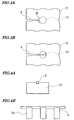
- the tip of the crack 5 is heated with only the linear heat source without local cooling, the tip has a shape represented by a solid line 5a shown in Fig. 2.
- a substantially circle area 10 of the tip of the crack 5 is heated and then locally cooled, the tip contracts in an arrow direction A and opens largely as represented by a solid line 5b.
- the large opening at the tip of the crack 5 is formed by superposing a stress intensity factor caused by the linear heat source and a stress intensity factor caused by the local cooling, which is motive power for extending the crack.
- a contractive force A is produced on a surface of the glass substrate. Accordingly, the present invention is suitably for separating a relatively thin substrate.
- the contractive force represented by an arrow A shown in Fig. 2 is produced on the tip of the crack 5 by the local cooling to open the tip of the crack 5. It is therefore critical to the present invention to select an area to be cooled locally as shown in Fig. 3A. It is a key point that a front area 11 of the tip of the crack 5 should not be cooled locally. If the front area 11 is cooled locally, a contractive force represented by an arrow B is produced near the front area 11 where the crack 5 is to be extended to prevent opening such that the crack 5 cannot be extended. In an actual air spraying, an area 12 shown in Fig. 3B may be cooled locally not only the tip of the crack 5 but also the front of the crack 5 depending on air diffusion.
- a contractive force for facilitating opening and a contractive force for retarding opening exist.
- the front cooled area (represented by slant lines) is needed to be as minimum as possible.
- the nozzle 9 is disposed inclined backward to the crack 5 to spray air backward.
- the area local cooled may be in a shape of circle, ellipse and rectangle, but not limited thereto.
- a size of the local cooled area is represented by a diameter (or length) X along an extending direction of the crack 5 as shown in Fig. 2.
- a width of the glass substrate W is represented by a numerical relation of X/W>0.005. For example, in case that the width of the glass substrate is 1000mm, an area having a diameter of not less than 5mm is required to be cooled. If the diameter is less than 5mm, the contractive force A is insufficient to open the tip of the crack 5 that less contributes to extend the crack 5.
- An upper limit of the diameter is not especially required to be limited in view of an extension of the crack 5. The upper limit of the diameter may be decided depending on other conditions.
- the heater was switched on. It took 60 to 65 seconds to start extending a crack 5 from an end face flaw 4 on the substrate 2. Further, it took about 60 seconds to extend the crack 1100 mm in length to the end of the substrate 2.
- a temperature of the heater was about 135°C upon starting the crack extension from the end face flaw 4 and was about 215°C upon completion of separation.
- a temperature of the heating zone on the top surface of the glass substrate was about 50°C directly above the heater and about 25°C 5mm apart from the heater. Room temperature was 20°C.
- the substrate 2 can be separated by extending the crack 5 whereby the heating zone 2a on the glass substrate 2 is heated only to 50°C and is cooled locally to near room temperature with air sprayed from the nozzle 9.
- gas which is cooled to room temperature or less in advance, is sprayed to the heating zone 2a to be cooled locally, a greater contractive force A and a larger opening at the tip of the crack 5 are obtained so that the crack 5 extends easily.
- the cooled gas has a great cooling power to the glass substrate 2, therefore it is effective that the nozzle 9 is tilted backward to the crack 5 so as not to cool the front area 11 of the tip of the crack 5.
- the heater was switched on. It took longer time to increase temperature of the heater.
- the heater may be heated to predetermined temperature in advance and be contacted with the glass substrate 2, thereby shorten a time to start extending the crack 5 from the end face flaw 4.
- a method for supporting the heater will be described.
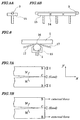
- the heater of the configuration in Fig. 1 is supported by a plurality of blocks 13 as shown in Fig. 4.
- a temperature of the heater contacted with the blocks 13 significantly decreases compared with that of remaining portions of the heater.
- the crack 5 stops temporary before the blocks and then, after seconds, extends to a position exceeding the blocks at a stretch.
- deviation is produced on a surface separated.
- linearity of the heater not supported by the blocks is not assured, resulting in poor linearity of separation as well.
- heater guilds 15 supporting substantially whole of the heater with reliefs 14 for thermal expansion as shown in Fig. 5 are effective.
- a sheath heater 3 supported by a heater guide 15 is disposed in contact with a bottom surface of the glass substrate 2, a contact portion 16 where the glass substrate 2 is contacted with the sheath heater 3 is cooled locally by air sprayed by a pair of nozzles 17, 17 disposed at both sides of the sheath heater 3.
- the air is sprayed toward the contact portion 16 with spreading to some extent to cool both of the glass substrate 2 near the contact portion 16 and the heater 3 concurrently and efficiently. Further, the air cools directly a heated surface of the glass substrate 2, whereby temperature decreases with a good response.
- An opening is readily formed on the tip of the crack 5 by cooling to extend the crack 5 in a short time.
- the air is sprayed to the contact portion 16, whereby a small clearance is formed between the glass substrate 2 and the sheath heater 3.
- the glass substrate 2 is cooled locally more efficiently.
- the glass substrate 2 is fixed and the nozzle is moved.
- the nozzle may be fixed and the glass substrate may be moved.
- control means for detecting an extending position of the crack 5 and correspondingly for moving the glass substrate 2 or the nozzle 9 are required.
- the means may be in various constructions. For example, a camera for detecting and an image processing are effective means.
- the crack extension speed is high and a decrease in the stress intensity factor is significantly retarded when the crack 5 approaches to the end of the substrate 2. Nevertheless, the crack extension speed is low when the crack 5 approaches to the end of the substrate 2. This is a peculiar problem for the separating method by extending the crack 5 using the linear heat source. Without local cooling, when the crack 5 approaches to the end and it becomes in a relation of d/W ⁇ 1.5, a stress at the end urges the crack 5 to be closed as shown in Fig. 11 and the stress intensity factor steeply decreases.
- an inverted stress is applied to the end so as to dissipate a stress for closing the crack 5 and the crack 5 is heated by the linear heat source, a decrease in the stress intensity factor at the end is compensated and the crack 5 can be extended to the end at approximately constant speed.
- the substrate 2 can be separated at a high speed without decreasing the speed.
- the inverted stress is applied to the end, i.e., a free surface, of the substrate in an inverted distribution to a stress distribution shown in Fig. 11, thereby obtaining a pseudo stress similar to that of a semi-infinite plate.
- a point C on a line to be separated on the end of the substrate 2 is nipped with a jig such as a grip to fix so as not to move it to the crack extension direction (x direction) as shown in Fig. 7A, and both sides of the point C, for example terminal portions B, B are held movably with a jig in a perpendicular direction (y direction) to the crack extension direction.
- the point C is fixed and both sides of the point C, for example the portions B, B are held with the jig such as the grip and are pulled to the x direction, thereby affecting external force to the portions B, B as shown in Fig. 7B.
- a stress is applied thereon to produce the moment M.
- Concrete means for applying the stress are not limited thereto.
- the strip plate substrate 2 composed of the non-metal material is contacted with the linear heat source 3 such as the sheath heater to form the heating zone 2a, the crack 5 is extended by applying a heat from the end face flaw 4 formed at one edge of the substrate in advance with the tip of the crack 5 being cooled locally and the cooled area being moved along the heating zone 2a, thereby extending the crack 5 to the end of the substrate 2 at a high speed to separate the substrate 2 as described above.
- the end face flaw 4 is introduced in order to easily produce the crack 5 at one edge 6 of the substrate 2. If the substrate has narrower width, the crack 5 extends only from the edge 6 introduced the end face flaw as described above.
- the crack 5 may extend from an opposite edge (end 6').
- the cracks 5 produced from the two edges faced approach each other upon extending and finally are linked together.
- the crack 5 linked has poor linearity causing a low separation accuracy, thereby lowering quality.
- a point P on the heating zone 2a near the edge 6' of the substrate 2 is cooled locally.
- the local cooling area is fixed to the point P and is not moved.
- the nozzle 9 is moved from the edge 6 to the edge 6' to extend the crack 5 produced from the end face flaw 4 to the edge 6'.
- a compressive stress in the y direction is produced on the edge 6' by cooling the point P fixed and a tensile stress in the y direction is produced on the edge 6. Accordingly, the crack extension is retarded at the edge 6' and is facilitated at the edge 6.
- the crack 5 can be assuredly extended only from the edge 6 at a shorter time.
Landscapes
- Engineering & Computer Science (AREA)
- Chemical & Material Sciences (AREA)
- Physics & Mathematics (AREA)
- Thermal Sciences (AREA)
- Materials Engineering (AREA)
- Organic Chemistry (AREA)
- Optics & Photonics (AREA)
- Plasma & Fusion (AREA)
- Mechanical Engineering (AREA)
- Re-Forming, After-Treatment, Cutting And Transporting Of Glass Products (AREA)
- Processing Of Stones Or Stones Resemblance Materials (AREA)
- Perforating, Stamping-Out Or Severing By Means Other Than Cutting (AREA)
Applications Claiming Priority (6)
| Application Number | Priority Date | Filing Date | Title |
|---|---|---|---|
| JP25151597 | 1997-09-17 | ||
| JP25151597 | 1997-09-17 | ||
| JP251515/97 | 1997-09-17 | ||
| JP31472897 | 1997-11-17 | ||
| JP314728/97 | 1997-11-17 | ||
| JP9314728A JPH11157863A (ja) | 1997-05-29 | 1997-11-17 | 非金属材料の分割方法 |
Publications (2)
| Publication Number | Publication Date |
|---|---|
| EP0903327A2 true EP0903327A2 (de) | 1999-03-24 |
| EP0903327A3 EP0903327A3 (de) | 1999-07-28 |
Family
ID=26540230
Family Applications (1)
| Application Number | Title | Priority Date | Filing Date |
|---|---|---|---|
| EP98117545A Withdrawn EP0903327A3 (de) | 1997-09-17 | 1998-09-16 | Verfahren zum Scheiden von nichtmetallischen Materialien |
Country Status (2)
| Country | Link |
|---|---|
| EP (1) | EP0903327A3 (de) |
| KR (1) | KR100267416B1 (de) |
Cited By (8)
| Publication number | Priority date | Publication date | Assignee | Title |
|---|---|---|---|---|
| DE10065688A1 (de) * | 2000-12-29 | 2002-07-11 | Schott Glas | Verfahren und Vorrichtung zum Schneiden eines Werkstückes aus sprödbrüchigem Werkstoff |
| US6664503B1 (en) | 1999-09-07 | 2003-12-16 | Asahi Glass Company, Ltd. | Method for manufacturing a magnetic disk |
| US6795274B1 (en) | 1999-09-07 | 2004-09-21 | Asahi Glass Company, Ltd. | Method for manufacturing a substantially circular substrate by utilizing scribing |
| DE102004035342A1 (de) * | 2004-07-21 | 2006-02-16 | Schott Ag | Verfahren und Vorrichtung zum Durchtrennen von Platten aus nichtmetallischen Werkstoffen |
| US20140017475A1 (en) * | 2011-06-07 | 2014-01-16 | Yasuo Teranishi | Method for cutting plate-like glass, and cutting device therefor |
| DE102014013262A1 (de) | 2014-09-08 | 2016-03-10 | Schott Ag | Vorrichtung und Verfahren zum Durchtrennen von mit einer Geschwindigkeit bewegten Werkstücken mechanisch spröder und nichtmetallischer Werkstoffe |
| CN108281383A (zh) * | 2018-01-22 | 2018-07-13 | 京东方科技集团股份有限公司 | 基板切割方法及阵列基板的制作方法 |
| CN115808817A (zh) * | 2021-09-15 | 2023-03-17 | 北京小米移动软件有限公司 | 显示基底、显示基板母板的切割方法及装置 |
Families Citing this family (5)
| Publication number | Priority date | Publication date | Assignee | Title |
|---|---|---|---|---|
| KR100634976B1 (ko) * | 2000-04-27 | 2006-10-16 | 미쓰보시 다이야몬도 고교 가부시키가이샤 | 유리 절단장치 |
| RU2327654C1 (ru) * | 2006-09-18 | 2008-06-27 | Открытое акционерное общество "Научно-исследовательский институт полупроводникового машиностроения" ОАО "НИИПМ" | Способ и устройство для группового разделения стеклопакетов на отдельные жидкокристаллические экраны |
| KR100817276B1 (ko) | 2006-11-03 | 2008-03-27 | 삼성전기주식회사 | 반도체 웨이퍼의 다이싱 장치 및 그 다이싱 방법 |
| JP5285736B2 (ja) | 2011-04-06 | 2013-09-11 | 三星ダイヤモンド工業株式会社 | 脆性材料基板の内周加工方法 |
| KR101631370B1 (ko) | 2014-07-03 | 2016-06-16 | 장석태 | 외기의 소독 및 이물질 제거가능한 외기공급장치 |
Family Cites Families (4)
| Publication number | Priority date | Publication date | Assignee | Title |
|---|---|---|---|---|
| DE2813302C2 (de) * | 1978-03-28 | 1979-09-13 | Fraunhofer-Gesellschaft Zur Foerderung Der Angewandten Forschung E.V., 8000 Muenchen | Verfahren und Vorrichtung zum geradlinigen Schneiden von Flachglas mit Hilfe von thermisch induzierten Spannungen |
| US4196830A (en) * | 1978-07-27 | 1980-04-08 | Ppg Industries, Inc. | Method of and apparatus for preventing premature severing of scored ribbon edges |
| US4190184A (en) * | 1978-08-23 | 1980-02-26 | Libbey-Owens-Ford Company | Method of and apparatus for thermally cutting glass |
| RU2024441C1 (ru) * | 1992-04-02 | 1994-12-15 | Владимир Степанович Кондратенко | Способ резки неметаллических материалов |
-
1998
- 1998-09-16 EP EP98117545A patent/EP0903327A3/de not_active Withdrawn
- 1998-09-17 KR KR1019980038390A patent/KR100267416B1/ko not_active Expired - Fee Related
Cited By (13)
| Publication number | Priority date | Publication date | Assignee | Title |
|---|---|---|---|---|
| US6664503B1 (en) | 1999-09-07 | 2003-12-16 | Asahi Glass Company, Ltd. | Method for manufacturing a magnetic disk |
| US6795274B1 (en) | 1999-09-07 | 2004-09-21 | Asahi Glass Company, Ltd. | Method for manufacturing a substantially circular substrate by utilizing scribing |
| DE10065688B4 (de) * | 2000-12-29 | 2004-05-06 | Schott Glas | Verfahren und Vorrichtung zum Schneiden eines Werkstückes aus sprödbrüchigem Werkstoff |
| DE10065688A1 (de) * | 2000-12-29 | 2002-07-11 | Schott Glas | Verfahren und Vorrichtung zum Schneiden eines Werkstückes aus sprödbrüchigem Werkstoff |
| US8763872B2 (en) | 2004-07-21 | 2014-07-01 | Schott Ag | Method and device for separating plates from mechanically brittle and nonmetal materials |
| DE102004035342A1 (de) * | 2004-07-21 | 2006-02-16 | Schott Ag | Verfahren und Vorrichtung zum Durchtrennen von Platten aus nichtmetallischen Werkstoffen |
| DE102004035342B4 (de) * | 2004-07-21 | 2007-12-27 | Schott Ag | Verfahren zum Durchtrennen von Platten aus nichtmetallischen Werkstoffen |
| US20140017475A1 (en) * | 2011-06-07 | 2014-01-16 | Yasuo Teranishi | Method for cutting plate-like glass, and cutting device therefor |
| US9458047B2 (en) * | 2011-06-07 | 2016-10-04 | Nippon Electric Glass Co., Ltd. | Method for cutting plate-like glass, and cutting device therefor |
| DE102014013262A1 (de) | 2014-09-08 | 2016-03-10 | Schott Ag | Vorrichtung und Verfahren zum Durchtrennen von mit einer Geschwindigkeit bewegten Werkstücken mechanisch spröder und nichtmetallischer Werkstoffe |
| CN108281383A (zh) * | 2018-01-22 | 2018-07-13 | 京东方科技集团股份有限公司 | 基板切割方法及阵列基板的制作方法 |
| CN108281383B (zh) * | 2018-01-22 | 2021-11-26 | 京东方科技集团股份有限公司 | 基板切割方法及阵列基板的制作方法 |
| CN115808817A (zh) * | 2021-09-15 | 2023-03-17 | 北京小米移动软件有限公司 | 显示基底、显示基板母板的切割方法及装置 |
Also Published As
| Publication number | Publication date |
|---|---|
| EP0903327A3 (de) | 1999-07-28 |
| KR100267416B1 (ko) | 2000-10-16 |
| KR19990029883A (ko) | 1999-04-26 |
Similar Documents
| Publication | Publication Date | Title |
|---|---|---|
| EP0903327A2 (de) | Verfahren zum Scheiden von nichtmetallischen Materialien | |
| KR100849696B1 (ko) | 취성재료의 스크라이브 방법 및 스크라이브 장치 | |
| JP4666391B2 (ja) | ガラス基板の分断方法 | |
| KR100932347B1 (ko) | 레이저 절단장치 및 레이저 절단방법 | |
| TWI415811B (zh) | 分割脆性材料板之方法 | |
| KR101069621B1 (ko) | 절단 방법 | |
| JP5325209B2 (ja) | 脆性材料基板の加工方法 | |
| EP3107868B1 (de) | Verfahren zum schneiden von radien bei flexiblem dünnglas | |
| US7142278B2 (en) | Method for producing a liquid crystal display apparatus | |
| KR101165982B1 (ko) | 취성 재료 기판의 가공 방법 | |
| JPH0929472A (ja) | 割断方法、割断装置及びチップ材料 | |
| US20160151929A1 (en) | Method of and apparatus for dividing plate member made of brittle material | |
| JP2835348B2 (ja) | 脆い材料のプレートを裂開する方法 | |
| KR100383883B1 (ko) | 유리기판 절단방법 및 절단장치 | |
| KR100551527B1 (ko) | 취성재료기판의 스크라이브 방법 및 스크라이브 장치 | |
| US20080053973A1 (en) | Method and apparatus for laser machining | |
| KR20000014954A (ko) | 엘씨디 글래스 절단 장치, 엘씨디 글래스 절단방법 및 이를이용한 대형 평판 표시 소자 제조 방법 | |
| JPH11157863A (ja) | 非金属材料の分割方法 | |
| KR100631304B1 (ko) | 레이저 빔을 이용한 유리기판 절단 장치 및 그 방법 | |
| KR100674061B1 (ko) | 반도체 소자 및 제조 방법 | |
| KR100904381B1 (ko) | 스크라이빙 방법 및 스크라이빙 장치 | |
| US20240076226A1 (en) | Glass substrate heat chamfering method and apparatus | |
| KR20070030112A (ko) | 레이저 절단장치 및 방법 | |
| JP2003137578A (ja) | 脆性材料の割断加工方法およびその加工装置、並びに電子部品の製造方法 | |
| JP2009084133A (ja) | 脆性材料のフルボディ割断方法 |
Legal Events
| Date | Code | Title | Description |
|---|---|---|---|
| PUAI | Public reference made under article 153(3) epc to a published international application that has entered the european phase |
Free format text: ORIGINAL CODE: 0009012 |
|
| AK | Designated contracting states |
Kind code of ref document: A2 Designated state(s): DE GB |
|
| AX | Request for extension of the european patent |
Free format text: AL;LT;LV;MK;RO;SI |
|
| PUAL | Search report despatched |
Free format text: ORIGINAL CODE: 0009013 |
|
| AK | Designated contracting states |
Kind code of ref document: A3 Designated state(s): AT BE CH CY DE DK ES FI FR GB GR IE IT LI LU MC NL PT SE |
|
| AX | Request for extension of the european patent |
Free format text: AL;LT;LV;MK;RO;SI |
|
| 17P | Request for examination filed |
Effective date: 19990622 |
|
| AKX | Designation fees paid |
Free format text: DE GB |
|
| 17Q | First examination report despatched |
Effective date: 20010912 |
|
| STAA | Information on the status of an ep patent application or granted ep patent |
Free format text: STATUS: THE APPLICATION HAS BEEN WITHDRAWN |
|
| 18W | Application withdrawn |
Withdrawal date: 20021106 |