EP0902397A2 - Verfahren und Vorrichtung für scalable Form coding/decoding durch das Verwenden von Scan-Interleaving - Google Patents
Verfahren und Vorrichtung für scalable Form coding/decoding durch das Verwenden von Scan-Interleaving Download PDFInfo
- Publication number
- EP0902397A2 EP0902397A2 EP98305288A EP98305288A EP0902397A2 EP 0902397 A2 EP0902397 A2 EP 0902397A2 EP 98305288 A EP98305288 A EP 98305288A EP 98305288 A EP98305288 A EP 98305288A EP 0902397 A2 EP0902397 A2 EP 0902397A2
- Authority
- EP
- European Patent Office
- Prior art keywords
- coding
- decoding
- scan
- scanning
- horizontal
- Prior art date
- Legal status (The legal status is an assumption and is not a legal conclusion. Google has not performed a legal analysis and makes no representation as to the accuracy of the status listed.)
- Granted
Links
Images


Classifications
-
- H—ELECTRICITY
- H04—ELECTRIC COMMUNICATION TECHNIQUE
- H04N—PICTORIAL COMMUNICATION, e.g. TELEVISION
- H04N19/00—Methods or arrangements for coding, decoding, compressing or decompressing digital video signals
- H04N19/20—Methods or arrangements for coding, decoding, compressing or decompressing digital video signals using video object coding
-
- G—PHYSICS
- G06—COMPUTING OR CALCULATING; COUNTING
- G06T—IMAGE DATA PROCESSING OR GENERATION, IN GENERAL
- G06T9/00—Image coding
- G06T9/20—Contour coding, e.g. using detection of edges
-
- H—ELECTRICITY
- H04—ELECTRIC COMMUNICATION TECHNIQUE
- H04N—PICTORIAL COMMUNICATION, e.g. TELEVISION
- H04N19/00—Methods or arrangements for coding, decoding, compressing or decompressing digital video signals
- H04N19/30—Methods or arrangements for coding, decoding, compressing or decompressing digital video signals using hierarchical techniques, e.g. scalability
Definitions
- the present invention relates to a coding and decoding of shape information for motional images, and more particularly, to an apparatus and method for scalably coding/decoding shapes by utilizing a scan interleaving method in which a scanning order of vertical and horizontal scannings is applied differently from each other in scalably coding/decoding the shapes.
- Fig. 1 shows a conceptual diagram providing the spatial scalable coding method.
- a base layer has a lower spatial resolution and an enhancement layer has a high spatial resolution.
- a general coding method is used on the base layer.
- images on the base layer are up-sampled, that is, the images on the base layer become a screen having a high resolution through an interpolation, and images of size equal to images on the enhancement layer are provided thereon.
- White arrow marks shown in Fig. 1 indicate a direction of a prediction.
- a compression efficiency is high in case that an image of an object is separated from its background then is coded.
- it needs to encode shape information for separating an object from a background on an image, separately from information of luminance and color signals in each of pixels constituting the object.
- the shape information is a binary image indicating the interior and the exterior of the object. That is, the interior of object may be as "1" and the exterior of object may be as "0".
- scalable coding process not only color information but also shape information is available to be encoded.
- shape information scalable coding method in case of using intra shape information of a base layer, a scan interleaving method is employed representatively.
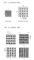
- Fig. 2 is a basic conceptual diagram of the scan interleaving for coding from a base layer to an enhancement layer.
- Rows of the first, third and fifth are reference scan lines and their values are known to a coder and a decoder. Their values may be pixel values of the base layer.
- the second and fourth rows are cord scan lines to be coded by the coder. In order to code a pixel value of a cord scan line, pixel values of two upper and lower reference scan lines are scanned. The correlation between the reference scan lines and the cord scan lines is as follows.
- pixel values of two scan lines and a pixel value of a cord scan line are same.
- shape information has a value of "0" on the background and a value of "1" on the object, or has its opposite value.
- Most pixels to be coded are included into such a case.
- pixel values on two reference scan lines are different from each other and this case is as a transitional sample, in which the pixel values should be coded. A position which the transitional sample is generated can be noted through the reference scan lines, thus the position information does not need to be transmitted.
- pixel values on two reference scan lines are same as each other meantime are different from a pixel value on a cord scan line.
- Such a case is as an exceptional sample, in which position information of the pixel that the exceptional sample is generated should be transmitted, meantime a pixel value does not need to be transmitted since it has a value opposite against pixel values of reference lines.
- TSD transitional sample data
- ESD exceptional sample data
- the enhancement layer has twice higher resolution all in the width and length directions than the base layer. If the base layer has a resolution of MxN, the enhancement layer has a resolution of (2xM) x (2xN).
- a pixel position of the base layer is constructed so that it may have a position value of the right lower of each of 2x2 blocks on the enhancement layer. Parts with one set of lines in Fig. 3(b) become each position of pixels which constitute the base layer.
- white blocks in Fig. 3(b) should be coded. At this time parts with one set of lines are the same as the value on the base layer, thus there is no need to code the parts with one set of lines again. The parts with one set of lines are utilized when the enhancement layer is coded.
- Figs. 4(a) to 4(d) represent vertical and horizontal scannings to code the enhancement layer.
- first, left and right pixel values of the base layer as pixels with one set of lines are used as reference values in coding parts with two sets of lines of the enhancement layer.
- Fig. 4(b) next, upper and lower pixel values of pixels shown as parts with one set of lines and encoded with the base layer at the first step are utilized as reference values to encode parts with two sets of lines on the enhancement layer.
- upper and lower pixel values of the base layer shown as parts with one set of lines are used as reference values in order to encode parts with two sets of lines of the enhancement layer.
- left and right pixel values of pixels shown as parts with one set of lines and coded with the base layer at the first step are utilized as reference values in order to encode parts with two sets of lines of the enhancement layer
- the method for using left and right pixel. values as a reference value is a horizontal scanning
- the method for using upper and lower pixel values as a reference value is a vertical scanning.
- the scan interleaving method has two scanning steps as afore-mentioned. In its scanning order there may be also two methods that the vertical scanning is first progressed and the horizontal scanning is next progressed, and the horizontal scanning is first progressed then the vertical scanning is next progressed. At present, one of such two scanning methods in the scan interleaving method is selected and used.
- a main cause for deciding coding information quantity in the scan interleaving method is influenced by generation quantity of the TSD and ESD. That is to say, the smaller the TSD and ESD are generated, the smaller the coding information quantity becomes.
- the generation quantity of the TSD and ESD in coding may become different according to a shape of shape information by an order of the vertical and horizontal scannings.
- the scanning should be progressed two times as the vertical and horizontal scannings.
- the number of coding pixels in the second scanning is more twice than the first scanning regardless an order of the vertical and horizontal scannings. Its reason is that pixels of the enhancement layer are coded in the first scanning referring to pixels of the base layer which are positioned skipping over each one block as shown in Figs. 4(a) and 4(c), and pixels already noted about their values through the first scanning are coded in succession in the second scanning. As shown as parts with two sets of lines in Figs. 4(a) to 4(d), 16 pixels in Figs. 4(a) and 4(c) indicating the first scanning should be scanned, and 32 pixels in Figs. 4(b) and 4(d) indicating the second scanning should be scanned.
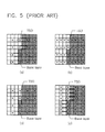
- Figs. 5(a) to 5(d) provides a generation state of TSD and ESD based on an order of a scanning direction for shape information having many vertical boundary lines.
- Figs. 5(a) and 5(b) show a method that the horizontal scanning is first executed and the vertical scanning is next performed.
- Figs. 5(c) and 5(d) show a method the vertical scanning is first executed and the horizontal scanning is next performed.
- 4 TSD's are generated in Fig. 5(a) as the first scanning process.
- Fig. 5(b) as the second scanning process, 1 TSD is generated.
- 1 TSD is generated.
- the total 5 TSD's are generated.
- a successive display of pixels is available through known pixel values on reference scan lines since pixels positioned between pixels constituting the base layer are scanned through the horizontal scanning.
- 1 TSD is generated in the first scanning and 8 TSD's are generated in the second scanning.
- the total 5 TsD's are generated.
- the total 9 TSD's are generated.
- the generation quantity of TSD may be less in a scanning order which the horizontal scanning first and the vertical scanning next are executed.
- a scanning order which the vertical scanning first and the horizontal scanning next are executed may make the generation quantity of the TSD less.
- the TSD and ESD may be generated in its quantity more than an opposite scanning order since the generation quantity of the TSD and ESD can become different according to such scanning order, if the scanning order is constantly fixed. That is, a coding efficiency falls since the bit quantity in such a case becomes more than the opposite scanning order.
- the present invention is directed to an apparatus and method for scalably coding/decoding shapes through a way of a scan interleaving that substantially obviate one or more of the problems due to limitations and disadvantages of the related art.
- An object of the present invention is to provide an apparatus and method for coding/decoding scalably shapes, which are capable of improving a coding and decoding efficiency, by applying a scanning order of vertical and horizontal scannings differently from each other to an image coding through a way of a scan interleaving, in coding images from a base layer and to an enhancement layer.
- Another object of the present invention is to provide an apparatus and method for coding/decoding scalably shapes by utilizing a scan interleaving way in which a scanning order based on a boundary line direction of a base layer can be decided so that coding bits may be generated in the small quantity.
- a scanning order of horizontal and vertical scannings is differently applied to an image coding from a base layer to an enhancement layer through a use of a scan interleaving way.
- the scanning order is decided by a direction of a boundary line, the number of TSDs, the number of ESDs, the sum of the TSD and ESD, the number of bits when the TSD was coded, the number of bits when the ESD was coded, the number of bits when the TSD and ESD were coded, and the total number of coding bits. Additional information having such decided scanning order and coding information are transmitted to a decoder.
- the decoder receives this additional information and decodes it in the scanning order.
- the additional information indicating the scanning order is coded by using a fixed length coding, a variable length coding, a fixed arithmetic coding and a variable arithmetic coding method.
- the additional information representing a scanning order, which is transmitted to each block, has much importance in the total.
- a method using a characteristic of a boundary line of a base layer as a method that the additional information for a scanning order is not transmitted.
- a coder and decoder can decide the same scanning order in a case of using only the base layer since the coder and decoder have the same base layer. That is, there is no need to transmit the additional information of the scanning order.
- the coding and decoding can be done by fixing the scanning order and moving symmetrically coded blocks or rotating the coded blocks 90 degrees centering on a diagonal line. That is to say, in case that the scanning order requires a preferential execution of a horizontal scanning or a preferential execution of a vertical scanning, the coding and decoding is realized by symmetrically moving coding blocks in a direction of a diagonal line or rotating the coding blocks 90 degrees under a state that the scanning order is fixed.
- Fig. 6 shows a block diagram providing the construction of one preferred embodiment for a scan interleaving coder in accordance with the present invention.
- a shape information extracting unit 60 extracts shape information from an inputted image and outputs its information.
- a base layer extraction unit 61 extracts pixel data corresponding to a base layer from the shape information data outputted from the shape information extraction unit 60, codes the pixel data by using the existed shape information coding method, decodes the data and outputs the data. Such a process is for using data of the same base layer in a coder and decoder.
- a scan order decision unit 62 compares lengths of horizontal and vertical boundary lines on the base layer outputted from the base layer extraction unit 61, and outputs a switching control signal according to its comparison result.
- a first switching unit 63 outputs the shape information outputted from the shape information extraction unit 60 and the base layer outputted from the base layer extraction unit 61 to a first direction scan unit 64 or a second direction scan unit 65 in response to the switching control signal outputted from the scan order decision unit 62.
- the first direction scan unit 64 receives the base layer data and the shape information, and executes a horizontal scanning first and a vertical scanning next.
- the second direction scan unit 65 receives the base layer data and the shape information, and performs the vertical scanning first and the horizontal scanning next.
- a shape of a required object can be extracted from another object and a background.
- one pixel per a block of a given size for example, a block of 2x2, a block of 4x4, etc., is extracted and the base layer is made, in the base layer extraction unit 61.
- the scan order decision unit 62 compares lengths of the horizontal and vertical boundary lines on the base layer.
- the scan order decision unit 62 controls the first switching unit 63 so that the shape information may be inputted to the first direction scan unit 64.
- the scan order decision unit 62 controls the first switching unit 63 so that the shape information may be inputted to the second direction scan unit 65.
- the first direction scan unit 64 includes a horizontal direction scan block 641 and a vertical direction scan block 642 as shown in Fig. 6.
- the horizontal direction scan block 641 executes a horizontal direction scanning on the shape information and the base layer data and outputs the scanning completed data after its scanning completion.
- the vertical direction scan block 642 receives the scanning completed data from the horizontal direction scan block 641 and performs a vertical direction scanning on the shape information and the base layer data.
- a scanning order from a vertical direction scan block 651 to a horizontal direction scan block 652 is only different from the scanning order from the horizontal direction scan block 641 to the vertical direction scan block 642, and its other functions are equal to them of the first direction scan unit 64.
- FIG. 7 sets forth a block diagram of one preferred embodiment for an inventive horizontal direction scan unit.
- a coding pixel extraction unit 71 extracts coding pixels from shape information.
- a horizontal adjacent pixel extraction unit 72 extracts pixels positioned on the right and left of a pixel extracted by the coding pixel extraction unit 71.
- a first comparison unit 73 compares pixels adjacent to the coding pixel outputted from the horizontal adjacent pixel extraction unit 72, and outputs a switching control signal.
- a second switching unit 74 switches the coding pixel and horizontal adjacent pixels to a TSD coding unit 77 or a third switching unit 76 in response to the switching control signal.
- a second comparison unit 75 compares the coding pixel and its adjacent pixels, and outputs a switching control signal.
- a third switching unit 76 switches the coding pixel and horizontal adjacent pixels to an ESD coding unit 78 or a decoder in response to the switching control signal of the second comparison unit 75.
- the TSD coding unit 77 codes the coding pixel inputted through the second switching unit 74.
- the ESD coding unit 78 codes the coding pixel inputted through the third switching unit 76.
- FIG. 8 offers a block diagram of one preferred embodiment for an inventive vertical direction scan unit.
- a coding pixel extraction unit 81 receives shape information and horizontal direction coding data, and extracts coding pixels from them.
- a vertical adjacent pixel extraction unit 82 receives the base layer data and the horizontal direction coding data outputted from the horizontal direction scan block 641 together, and extracts pixels positioned on the upper and lower sides of a pixel extracted by the coding pixel extraction unit 71.
- a third comparison unit 83 compares with each other vertical adjacent pixels outputted from the vertical adjacent pixel extraction unit 82, and outputs a switching control signal according to its comparison result.
- a fourth switching unit 84 switches the coding pixel and horizontal adjacent pixels to a TSD coding unit 87 or a fifth switching unit 86 in response to the switching control signal of the third comparison unit 83.
- a fourth comparison unit 85 compares the coding pixel and its adjacent pixels, and outputs a switching control signal.
- a fifth switching unit 86 switches the coding pixel and vertical adjacent pixels to an ESD coding unit 88 or the decoder in response to the switching control signal of the fourth comparison unit 85.
- the TSD coding unit 87 codes the coding pixel inputted through the fourth switching unit 84.
- the ESD coding unit 88 codes the coding pixel inputted through the fifth switching unit 86.
- the horizontal direction scan block 641 is positioned ahead of the vertical direction scan block 642 as shown in Fig. 6.
- the shape information is inputted to the coding pixel extraction unit 71 through the first switching unit 63, wherein the shape information is enhancement layer data, and the pixels shown as parts with two sets of lines in Fig. 4 are sequentially extracted by the coding pixel extraction unit 71.
- the horizontal adjacent pixel extraction unit 72 receives positions of pixels extracted by the coding pixel extraction unit 71, and extracts pixels of the base layer positioned on the right and left of the coding pixel, for example, horizontal adjacent pixels 42, 44 of a coding pixel 43 in Fig. 4.
- base layer pixels on a second column are copied on the left of the block, or corresponding pixels of an adjacent left block are copied.
- base layer pixels on a second row are copied on the upper side of a block, or corresponding pixels of an adjacent upper block are copied.
- the pixels 42, 44 extracted by the horizontal adjacent pixel extraction unit 72 are inputted to the first comparison unit 73 then compared therein.
- the second switching unit 74 outputs a switching control signal for connecting the coding pixel and horizontal adjacent pixels with the TSD coding unit 77 since the extracted pixels correspond to the TSD.
- the extracted pixels may be the ESD, thus the second switching unit 74 outputs a switching control signal for connecting the coding pixel and horizontal adjacent pixels with the third switching unit 76.
- the coding pixel and one horizontal adjacent pixel outputted from the coding pixel extraction unit 71 and the horizontal adjacent pixel extraction unit 72 are compared with each other in the second comparison unit 75.
- the pixels correspond to the ESD
- the third switching unit 76 outputs a switching control signal for connecting the coding pixel and the horizontal adjacent pixels with the ESD coding unit 78.
- the second comparison unit 75 outputs the pixels to the vertical direction scan block 642 since the pixels do not need to be coded.
- the horizontal direction scan block 641 codes pixels with two sets of lines in Fig. 4(a) and outputs them to the vertical direction scan block 642.
- Fig. 8 presents one embodiment of the vertical direction scan block 642.
- a coding pixel extraction unit 81 extracts pixels with two sets of lines in Fig. 4(b) from shape information of an enhancement layer and horizontal direction coding data outputted from the horizontal direction scan block 641.
- a vertical adjacent pixel extraction unit 82 receives positions of pixels extracted by the coding pixel extraction unit 81, and extracts pixels positioned on the upper and lower sides of coding pixel, for example, vertical adjacent pixels 46, 47 of coding pixel 45 in Fig. 4(b).
- base layer pixels on a second row or second column are copied or corresponding pixels of neighboring block are copied.
- the pixels 46, 47 extracted by the vertical adjacent pixel extraction unit 72 are inputted to the first comparison unit 83 and compared with each other.
- the fourth switching unit 84 outputs a switching control signal for connecting the coding pixel and the horizontal adjacent pixels with the TSD coding unit 87.
- the fourth switching unit 84 outputs a switching control signal for connecting the coding pixel and the horizontal adjacent pixels with the fifth switching unit 86 since the pixels may correspond to the ESD.
- the coding pixel and one vertical adjacent pixel outputted from the coding pixel extraction unit 81 and the vertical adjacent pixel extraction unit 82 are compared with each other in the fourth comparison unit 85.
- the fourth comparison unit 85 is related to the ESD, thus the fifth switching unit 86 outputs a switching control signal for connecting the coding pixel and the vertical adjacent pixels with the ESD coding unit 88.
- the pixels are outputted to the decoder since the pixels do not need to be coded.
- the horizontal direction scan block 641 and vertical direction scan block 642 are included into the first scan unit 64, in which the horizontal direction scanning is first executed, and the vertical direction scanning is next performed.
- the vertical direction scan block 651 is positioned ahead of the horizontal direction scan block 652 as shown in Fig. 6. It is therefore obvious that horizontal direction coding data is not inputted to the coding pixel extraction unit 81 and the vertical adjacent pixel extraction unit 82, and the vertical direction coding data with shape information and base layer data is inputted to the coding pixel extraction unit 71 and the horizontal adjacent pixel extraction unit 72.
- Fig. 9 illustrates the construction of one preferred embodiment for a scan interleaving decoder in accordance with the present invention.
- a base layer decoding unit 91 receives base layer coding data transmitted from the coding apparatus and decodes the data.
- a scan order decision unit 92 compares lengths of horizontal and vertical boundary lines on the base layer outputted from the base layer decoding unit 91, and outputs a switching control signal according to its comparison result.
- a sixth switching unit 93 switches coding data transmitted from the coding apparatus and the base layer data outputted from the base layer decoding unit 91 to a first direction scan decoding unit 94 or a second direction scan decoding unit 95 in response to the switching control signal outputted from the scan order decision unit 92.
- the first direction scan decoding unit 94 receives the base layer data and the coding data, and executes a horizontal decoding scanning first and a vertical decoding scanning next.
- the second direction scan decoding unit 95 receives the base layer data and the coding data, and performs the vertical decoding scanning first and the horizontal decoding scanning next.
- the base layer is coded separately from enhancement layer data, and transmitted to the decoder.
- the base layer decoding unit 91 receives coded base layer and decodes it.
- the scan order decision unit 92 compares lengths of the horizontal and vertical boundary lines on the decoded base layer. Namely, the number of right or left adjacent pixels and pixels having the other value, which corresponds to a length of the vertical boundary line, is compared with the number of upper or lower adjacent pixels and pixels having the other value, which corresponds to a length of the horizontal boundary line.
- the scan order decision unit 92 controls the sixth switching unit 93 so that the base layer and the coding data may be inputted to the first direction scan decoding unit 94.
- the scan order decision unit 92 controls the sixth switching unit 93 so that the base layer and the coding data may be inputted to the second direction scan decoding unit 95.
- the first direction scan decoding unit 94 includes a horizontal direction decoding scan block 941 and a vertical direction decoding scan block 942 as shown in Fig. 9.
- the horizontal direction decoding scan block 941 executes a horizontal direction decoding scanning on the coding data and the base layer data and outputs the scanning completed data after its scanning completion.
- the vertical direction decoding scan block 942 receives the scanning completed data from the horizontal direction decoding scan block 941 and performs a vertical direction decoding scanning on the coding data and the base layer data.
- a scanning order from a vertical direction decoding scan block 951 to a horizontal direction decoding scan block 952 is only different from the scanning order from the horizontal direction decoding scan block 941 to the vertical direction decoding scan block 942, and its other functions are equal to them of the first direction scan decoding unit 94.
- FIG. 10 represents a block diagram of one embodiment for an inventive horizontal direction decoding scan block.
- a horizontal adjacent pixel extraction unit 101 receives the base layer data transmitted from the base layer decoding unit 91 and extracts pixels positioned on the right and left of a pixel to be decoded.
- a fifth comparison unit 103 compares pixels adjacent to the decoding pixel outputted from the horizontal adjacent pixel extraction unit 101, and outputs a switching control signal.
- a seventh switching unit 102 switches the coding data and horizontal adjacent pixels to a TSD decoding unit 104 or an eighth switching unit 105 in response to the switching control signal of the fifth comparison unit 103.
- the TSD decoding unit 104 decodes the coding data inputted through the seventh switching unit 102.
- the eighth switching unit 105 outputs the coding data and horizontal adjacent pixels transmitted from the coding apparatus to an ESD decoding unit 106 or an adjacent pixel copy unit 107 in response to an ESD of corresponding decoding pixel among the coding data.
- the ESD decoding unit 106 decodes the coding pixel inputted through the eighth switching unit 105.
- the adjacent pixel copy unit 107 stores horizontal adjacent pixel values of decoding pixels which do not correspond to a TSD or ESD.
- Fig. 11 is a block diagram of one embodiment for an inventive vertical direction decoding scan block.
- a vertical adjacent pixel extraction unit 111 receives horizontal direction decoding data and the base layer outputted from the horizontal direction scan block 641, and extracts pixels positioned on the upper and lower sides of decoding pixel from them.
- a sixth comparison unit 113 compares with one another vertical adjacent pixels outputted from the vertical adjacent pixel extraction unit 111, and outputs a switching control signal according to its comparison result.
- a ninth switching unit 112 switches the coding data and vertical adjacent pixels to a TSD decoding unit 114 or a tenth switching unit 115 in response to the switching control signal of the sixth comparison unit 113.
- the TSD decoding unit 114 decodes the coding data inputted through the ninth switching unit 112.
- the tenth switching unit 115 switches the vertical adjacent pixels and the coding data transmitted from the coding apparatus to an ESD decoding unit 116 or an adjacent pixel copy unit 117 according as corresponding decoding pixel among the coding data corresponds to ESD or does not correspond to the ESD.
- the ESD decoding unit 116 decodes the vertical adjacent pixel and coding data inputted through the tenth switching unit 115.
- the adjacent pixel copy unit 117 copies decoding pixels as horizontal adjacent pixel values.
- the horizontal direction decoding scan block 941 is positioned ahead of the vertical direction decoding scan block 942.
- the coding data and the base layer through the sixth switching unit 93 are inputted to the horizontal direction decoding scan block 941, wherein the coding data is data which the enhancement layer was coded.
- the horizontal adjacent pixel extraction unit 101 extracts horizontal adjacent pixels, 42, 44 in Fig. 4(a) of decoding pixel, for example, a pixel 43 on a second row and third column in Fig. 4(a), sequentially by pixels of the base layer outputted from the base layer decoding unit 91.
- base layer pixels on a second column are copied on the left of a block and then used.
- the pixels 42, 44 extracted by the horizontal adjacent pixel extraction unit 101 are inputted to the fifth comparison unit 103 and compared with each other.
- the fifth comparison unit 103 controls so that the seventh switching unit 102 may switch the coding data and horizontal adjacent pixels to the TSD decoding unit 104.
- the pixels are available to be the ESD, thus the seventh switching unit 102 outputs a control signal for connecting the coding data and horizontal adjacent pixels with the eighth switching unit 105.
- the eighth switching unit 105 is controlled by the ESD so that the coding data and horizontal adjacent pixel transmitted from the coding apparatus may be switched to the ESD decoding unit 106.
- the pixel does not need to be coded, thus the pixel is outputted to the adjacent pixel copy unit 107.
- the horizontal direction decoding scan block 941 decodes pixels shown with two sets of lines in Fig. 4(a) and outputs them to the vertical direction decoding scan block 942.
- the vertical adjacent pixel extraction unit 111 extracts vertical adjacent pixels, 49, 50 in Fig. 4(c) of decoding pixel, for example, a pixel 48 on a second row and second column in Fig. 4(c), sequentially by pixels of the base layer and horizontal direction decoding data outputted from the horizontal direction decoding scan block 941.
- the vertical adjacent pixel extraction unit 111 decodes the pixels by using a pixel value on a corresponding position of its neighboring block or doubly using the first row of the base layer.
- the pixels 49, 50 extracted by the vertical adjacent pixel extraction unit 111 are inputted to the sixth comparison unit 113 and compared with each other.
- the ninth switching unit 112 outputs a switching control signal for connecting the coding data and the vertical adjacent pixels 49, 50 with the TSD decoding unit 114.
- the ninth switching unit 112 outputs a switching control signal for connecting the coding data and the vertical adjacent pixels 49, 50 with the tenth switching unit 115 since the pixels may correspond to the ESD.
- the tenth switching unit 115 is controlled by the ESD so that the coding data and vertical adjacent pixel transmitted from the coding apparatus may be switched to the ESD decoding unit 116.
- the pixel does not need to be coded, thus the pixel is outputted to the adjacent pixel copy unit 117.
- the horizontal direction decoding scan block 941 and vertical direction decoding scan block 942 are included into the first direction scan decoding unit 94, in which the horizontal direction scanning is first executed, and the vertical direction scanning is next performed.
- the vertical direction decoding scan block 951 is positioned ahead of the horizontal direction decoding scan block 952 as shown in Fig. 9.
- Fig. 12 presents a flow chart showing a scalable shape information coding method through a use of a scan interleaving.
- a scan order for generating coding bits in the small quantity is decided, since the generation quantity of coding bits is different according to a scan order of horizontal and vertical directions.
- the vertical scanning is executed in a step ST125 and a horizontal scanning is performed in a step ST126.
- the horizontal scanning is executed in a step ST123 and a vertical scanning is performed in a step ST124.
- a direction having larger value as its comparison result is decided to be scanned first. For instance, when a scanning is horizontally executed as shown in Fig. 13(b), 8 pixels having values different from one another are generated, and when a vertical scanning is done as shown in Fig. 13(a), 6 pixels having other values are generated. Namely, since the number of pixels having other values is more on a horizontal direction, a possibility for a TSD generation is higher on the horizontal direction when an enhancement layer is coded.
- the total generation number of TSDs can be lessened by executing a horizontal scanning first and a vertical scanning next. Since a coder and a decoder include the same base layer and the decoder can thus know a scan direction by the same method, a decoding can be done without a transmission of additional information having a scan direction.
- Fig. 14 is a flow chart presenting one embodiment of a method for deciding a scan order, in which coding bits can be generated in a small quantity.
- a base layer is extracted from shape information, and the number of pixels adjacent vertically on the base layer, which have other values, is calculated, the number being as N1 corresponding to a length of a horizontal boundary line.
- the number of pixels adjacent horizontally on the base layer, which have other values is calculated, the number being as N2 corresponding to a length of a vertical boundary line.
- a step 143 it is detected whether or not the number of pixels adjacent vertically, which have other values, namely, N1 is larger than the number of pixels adjacent horizontally, which have other values, namely, N2.
- N1 > N2 in a step ST144, a value of a flag, Order, indicating a scan order, is determined as "1".
- a value of a flag, Order, indicating a scan order is determined as "0".
- coding data on the base layer is transmitted to the decoder, and the decoder decodes the base layer, to thereby compare lengths of the vertical and horizontal boundary lines and then be able to know a scan order decided in the coder. Therefore, there is no need to transmit additional information indicating a scan order to the decoder.
- an enhancement layer is coded by using a base layer, a horizontal scanning is not available to be done in a coding a first column of the enhancement layer since pixels of a base layer to be referred are positioned only on the right side as shown in Figs. 4(a) and 4(c). In such a case, therefore, as shown in Fig.
- a first column of the most right of a left block, 151 is used. If there is no the left block, a first column of the base layer is copied on the left of a first column on the enhancement layer and then the horizontal scanning is done by the scan interleaving method.
- a vertical scanning is not available to be done since pixels of the base layer to be referred are positioned only on the lower side as shown in Fig. 4(c). In this case, thus, as shown in Fig. 15, a first row 152 of the lowest side of an upper block is used. If there is no the upper block, a first row of the base layer is copied on an upper side of a first row on the enhancement layer and then a vertical scanning is done by the scan interleaving method.
- two kinds of data, TSD and ESD should be coded. A scan order which the TSD and ESD can be a little generated should be decided since the generation quantity of TSD and ESD may become different according to the scan order.
- Fig. 16 provides a flow chart setting forth a method for deciding a scan order based on a generation quantity of TSD and ESD in the invention.
- a VOP(video object plane) or a block of a given size e.g., 4x4, 2x2, etc.
- N_H the number of TSDs(ESDs) in the horizontal scanning
- the VOP is selected from the MPEG-4 and a polygonal domain for coding in an object unit.
- the coding number of TSDs (ESDs), N_V for the VOP or the block of a given size in the vertical scanning is computed.
- a step ST163 the N_H and N_V are added up and the number of the total TSDs (ESDs) generated in the horizontal preferential scan order, N_HV, is counted.
- the VOP or a block of a given size is extracted from the shape information, and the number of TSDs(ESDs) in the vertical scanning, N_V, is calculated.
- the coding number of TSDs (ESDs) in the horizontal scanning, for the VOP or the block of a given size, N_H is computed.
- the N_H and N_V are added up and the number of the total TSDs (ESDs) generated in the vertical preferential scan order, N_VH, is counted.
- a step 167 it is detected whether or not it is N_HV > N_VH.
- N_HV > N_VH in a case of N_HV > N_VH, the flag(Order) indicating the scan order is determined as "1", to thereby represent a priority order of the vertical (horizontal) scanning.
- the flag(Order) indicating the scan order in a step ST169, is determined as "0", to thereby represent a priority order of the horizontal (vertical) scanning.
- the additional information indicating the scan order e.g., flag(Order) data
- the decoder receives the additional information and decodes the base layer to the enhancement layer according to its scan order.
- the additional information may be represented by fixed length coding, variable length coding, fixed arithmetic coding and variable arithmetic coding methods.
- the quantity of information generated in coding the TSD and ESD becomes different according to coding methods, therefore, the quantity of information does not always becomes much when the generation quantity of TSD is much, the quantity of information does not always becomes much when the generation quantity of ESD is much.
- actually coding the TSD and ESD and comparing its generating information quantity can be more exact, since as afore-mentioned the quantity of coding information for respective TSD and ESD is different from each other.
- the TSD(ESD) generated in such a case is coded.
- the number of bits generated in such a coding is compared with the number of bits gotten in coding the TSD(ESD) generated in case that the vertical scanning is executed first and the horizontal scanning is executed next.
- the case that the number of coding bits on the TSD(ESD) is gotten in the small quantity can be decided as the scan order.
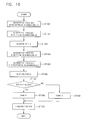
- Fig. 17 shows a flow chart setting forth a method for deciding a scan order based on the coding bit quantity of TSD and ESD in the invention.
- a VOP or a block of a given size is extracted from the shape information and the coding bit number of TSDs(ESDs) in the horizontal scanning, N_H, is calculated.
- the coding bit number of TSDs (ESDs), N_V, for the VOP or the block of a given size in the vertical scanning is computed.
- the N_H and N_V are added up and the coding bit number of the total TSDs (ESDs) generated in the horizontal preferential scan order, N_HV, is counted.
- a step ST174 the VOP or the block of a given size is extracted from the shape information, and the coding bit number of TSDs(ESDs) in the vertical scanning, N_V, is calculated.
- the coding bit number of TSDs (ESDs) in the horizontal scanning, N_H is computed.
- the N_H and N_V are added up and the coding bits of the total TSDs (ESDs) generated in the vertical preferential scan order, N_VH, is counted.
- a step 177 it is detected whether or not it is N_HV > N_VH.
- the flag(Order) indicating the scan order is determined as "1", to thereby represent a priority order of the vertical (horizontal) scanning.
- the flag(Order) indicating the scan order is determined as "0", to thereby represent a priority order of the horizontal (vertical) scanning.
- the flag(Order) indicating the scan order is transmitted to the decoder.
- the sum of TSD and ESD gotten in executing the horizontal scanning is compared with the sum of TSD and ESD gotten in executing the vertical scanning. As its comparison result, a scanning for a direction that the sum of TSD and ESD is larger, may be performed first.
- Fig. 18 offers a flow chart providing a method for deciding a scan order based on the generation quantity sum of TSD and ESD in the invention.
- a VOP or a block of a given size is extracted from shape information and the sum of TSD and ESD in the horizontal scanning, N_H, is calculated.
- the sum of TSD and ESD in the vertical scanning, N_V is computed.
- the N_H and N_V are added up and the number of the total TSD and ESD generated in the horizontal preferential scan order, N_HV, is counted.
- the sum of TSD and ESD in the vertical scanning, N_V is calculated.
- a step ST185 the sum of TSD and ESD in the horizontal scanning, N_H, is computed.
- the N_H and N_V are added up and the sum of the total TSD and ESD generated in the vertical preferential scan order, N_VH, is counted.
- a step 187 it is detected whether or not it is N_HV > N_VH.
- the flag(Order) indicating the scan order is determined as "1", to thereby represent a priority order of the vertical (horizontal) scanning.
- the flag(Order) indicating the scan order is determined as "0", to thereby represent a priority order of the horizontal (vertical) scanning.
- the flag(Order) indicating the scan order is transmitted to the decoder.
- Fig. 19 illustrates a flow chart providing a method for deciding a scan order based on the generation bit sum of TSD and ESD in the invention.
- a VOP or a block of a given size is extracted from shape information and the bit sum gotten in coding TSD and ESD in the horizontal scanning, N_H, is calculated.
- the bit sum gotten in coding TSD and ESD in the vertical scanning, N_V is computed.
- the N_H and N_V are added up and the bit sum generated in coding the total TSD and ESD in the horizontal preferential scan order, N_HV, is counted.
- a step ST194 the bit sum gotten in coding the TSD and ESD in the vertical scanning, N_V, is calculated.
- the sum of TSD and ESD in the horizontal scanning, N_H is computed.
- the N_H and N_V are added up and the bit sum gotten in coding the total TSD and ESD generated in the vertical preferential scan order, N_VH, is counted.
- a step 197 it is detected whether or not it is N_HV > N_VH.
- the flag(Order) indicating the scan order is determined as "1", to thereby represent a priority order of the vertical (horizontal) scanning.
- the flag(Order) indicating the scan order is determined as "0", to thereby represent a priority order of the horizontal (vertical) scanning.
- the flag(Order) indicating the scan order is transmitted to the decoder.
- Fig. 20 presents a flow chart showing a scalable shape information decoding method through a use of a scan interleaving.
- a decoding apparatus can not know a scan order of vertical and horizontal scannings in coding.
- lengths of horizontal and vertical boundary lines on the base layer are compared, and the scan order is decided.
- the vertical decoding scanning is executed in a step ST205 and a horizontal decoding scanning is performed in a step ST206.
- the horizontal decoding scanning is executed in a step ST203 and the vertical decoding scanning is performed in a step ST204.
- the scan order is decided by detecting the generation quantity of TSD and ESD according to the scan order, the scan order decided in the coding apparatus should be transmitted to the decoding apparatus as the additional information.
- Fig. 21 depicts a flow chart showing a scalable shape information decoding method in which additional information indicating a scan order is transmitted, in accordance with the present invention.
- a step ST211 receives coding data, coding base layer and the additional information.
- the vertical decoding scanning is executed in a step ST215 and a horizontal decoding scanning is performed in a step ST216.
- the horizontal decoding scanning is executed in a step ST213 and the vertical decoding scanning is performed in a step ST214.
- the scan direction is fixed, e.g., the horizontal direction first and the vertical direction next or the vertical direction first and the horizontal direction next, instead of changing the scan direction for the sake of a sequential scan in an actual scanning; and then, a block to be scanned is moved in the right and left symmetrical way centering on a diagonal line, or is rotated 90 degrees, in order for the scanning.
- Fig. 22 provides one embodiment of a coding apparatus in which a scan order is fixed and a scanning block is symmetrically moved, in the invention. This embodiment is for the scan order that the horizontal scanning is performed first and the vertical scanning is executed next, but a case of a scan order such as the vertical scanning first and the horizontal scanning next, may have the same description, as follows.
- a scan order decision unit 221 compares lengths of horizontal and vertical boundary lines on the base layer, and outputs a switching control signal according to its comparison result.
- a switching unit 222 switches an enhancement layer and the base layer to first and second symmetrical movement units 223, 224 in response to the switching control signal outputted from the scan order decision unit 221.
- a horizontal direction scan unit 225 and a vertical direction scan unit 226 scan the enhancement layer and the base layer horizontally and vertically.
- the scan order decision unit 221 compares lengths of the horizontal and vertical boundary lines on the base layer.
- the scan order decision unit 221 controls the switching units 222 to switch the enhancement layer and the base layer to the first and second symmetrical movement units 223, 224.
- the first and second symmetrical movement units 223, 224 moves symmetrically the enhancement layer and the base layer centering on a diagonal line, and outputs it.
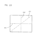
- the scan order is fixed as the horizontal scanning first and the vertical scanning next, when the horizontal boundary line 230 is symmetrically moved centering on the diagonal line 231 as shown in Fig. 23, the horizontal boundary line 230 is converted into the vertical boundary line 230. That is, the generation quantity of coding bits can be reduced as afore-mentioned.
- the scan order is fixed as the vertical scanning first and the horizontal scanning next. Accordingly, when the enhancement layer and the base layer are symmetrically moved, it is converted the horizontal boundary line into the vertical boundary line and the vertical boundary line into the horizontal boundary line. Even though the horizontal scanning first and the vertical scanning next are executed under a state that the vertical boundary line is longer than the horizontal boundary line, the scanning is done in a direction which the coding bits can be generated in less quantity without a change of a hardware.
- Fig. 24 shows a flow chart providing a scalable coding method in which a scan order is fixed and a scanning block is symmetrically moved, in the invention.
- a scan order is predetermined
- the coding apparatus and the decoding apparatus perform the coding/the decoding by the predetermined scan order, e.g., the horizontal scanning first and the vertical scanning next, and data indicating the scan order, e.g., determining as "1", is determined.
- a scan order deciding methods it is detected what scan order can be used in order for a coding bit generation of small quantity, e.g., methods for deciding lengths of horizontal and vertical boundary lines on the base layer and deciding by additional information transmitted from the coding apparatus.
- a step ST242 it is detected whether or not the decided scan order for the coding bit generation of small quantity is the fixation scan order.
- the fixation scan order in a step ST244, the horizontal scanning is first performed in the fixed scan order, and in a step ST245 the vertical scanning is done next. In case that it is not the fixation scan order, the block is rotated 90 degrees in a step ST243, and the horizontal and vertical scannings are done.
- Fig. 25 represents one embodiment of a decoding apparatus in which a scan order is fixed and a scanning block is symmetrically moved, in the invention. This embodiment is for the scan order that the horizontal scanning is performed first and the vertical scanning is executed next, but a case of a scan order such as the vertical scanning first and the horizontal scanning next, may have the same description, as follows.
- a base layer decoding unit 250 decodes a base layer in coding data transmitted from the coding apparatus.
- a scan order decision unit 251 compares lengths of horizontal and vertical boundary lines on the base layer, and outputs a switching control signal according to its comparison result.
- a switching unit 252 switches the base layer to a symmetrical movement unit 253 in response to the switching control signal outputted from the scan order decision unit 251.
- the symmetrical movement unit 253 symmetrically moves the base layer outputted through the switching unit 252 centering on a diagonal line or rotates it 90 degrees and outputs it.
- a horizontal direction decoding scan unit 254 and a vertical direction decoding scan unit 255 scan the base layer outputted through the symmetrical movement unit 253 or not through it, horizontally and vertically.
- a second switching unit 256 switches the enhancement layer outputted from the vertical direction decoding scan unit 255 to a converse symmetrical movement unit 257 in response to the switching control signal of the scan order decision unit 251.
- the converse symmetrical movement unit 257 symmetrically moves the enhancement layer inputted through the second switching unit 256 in an opposite direction to a direction of the symmetrical movement unit 253, or rotates the enhancement layer 90 degrees, to thereby generate and output an original enhancement layer which is not moved symmetrically.
- the scan order decision unit 251 compares lengths of the horizontal and vertical boundary lines on the base layer. In case the horizontal boundary line is longer than the vertical boundary line, coding data transmitted from a transmission side is coded in a preferential vertical scanning, thus the scan order decision unit 251 controls the switching units 252 to switch the base layer to the symmetrical movement unit 253.
- Such symmetrical movement of the base layer has reasons that the base layer is transmitted without a symmetrical movement in coding and the enhancement layer is coded after the symmetrical movement and then transmitted.
- the symmetrical movement unit 253 moves symmetrically the base layer like the coding side and outputs it.
- the scan order decision unit 251 controls the switching units 252 to switch the base layer to the horizontal direction decoding scan unit 254 and the vertical direction decoding scan unit 255, not through the first symmetrical movement unit 253.
- the symmetrical movement unit 253 moves symmetrically the base layer centering on the diagonal line and output it as afore-mentioned.
- the horizontal direction decoding scan unit 254 and the vertical direction decoding scan unit 255 decode the base layer and the enhancement layer.
- the base layer and the enhancement layer are inputted to the horizontal direction decoding scan unit 254 and the vertical direction decoding scan unit 255 at the same time, but the vertical direction decoding scan unit 255 receives the decoding data from the horizontal direction decoding scan unit 254, after that, executes the vertical decoding scanning, as explained in Figs. 10 and 11.
- converse symmetrical movement is executed. That is, in case that the base layer is through the symmetrical movement unit 253, the second switching unit 256 switches the enhancement layer outputted from the vertical direction decoding scan unit 255 to the converse symmetrical movement unit 257 in response to the switching control signal of the scan order decision unit 251.
- the converse symmetrical movement unit 257 symmetrically moves the enhancement layer inputted through the second switching unit 256 in an opposite direction to that of the symmetrical movement unit 253, to thereby generate and output an original enhancement layer which is not moved symmetrically
- Fig. 26 shows a flow chart providing a scalable decoding method in which a scan order is fixed and a scanning block is symmetrically moved, in the invention.
- a scan order is predetermined
- the decoding apparatus performs the decoding in the same scan order as that of the coding apparatus, e.g., the horizontal scanning first and the vertical scanning next, and data indicating the scan order, e.g., determining as "1", is determined.
- a scan order deciding methods it is detected what scan order can be used in order for a coding bit generation of small quantity, e.g., methods for deciding lengths of horizontal and vertical boundary lines on the base layer and deciding by additional information transmitted from the coding apparatus.
- a step ST262 it is detected whether or not the decided scan order for the coding bit generation of small quantity is the fixation scan order.
- the fixation scan order in a step ST264, the horizontal decoding scanning is first performed in the fixed scan order, and in a step ST265 the vertical decoding scanning is done next. In case that it is not the fixation scan order, the block is symmetrically moved in a step ST263, and the horizontal and vertical decoding scannings are done on it.
- the generating quantity of TSD and ESD and the generating bit number can be reduced in the total quantity by employ, differently from each other, a scan order of vertical and horizontal scannings based on a generation frequency of TSD and ESD or a type of boundary lines on images, in coding enhancement layers by utilizing a scan interleaving method, thereby heightening an efficiency of the coding.
Landscapes
- Engineering & Computer Science (AREA)
- Multimedia (AREA)
- Physics & Mathematics (AREA)
- General Physics & Mathematics (AREA)
- Theoretical Computer Science (AREA)
- Signal Processing (AREA)
- Compression Or Coding Systems Of Tv Signals (AREA)
- Compression, Expansion, Code Conversion, And Decoders (AREA)
- Compression Of Band Width Or Redundancy In Fax (AREA)
Applications Claiming Priority (2)
| Application Number | Priority Date | Filing Date | Title |
|---|---|---|---|
| KR9730727 | 1997-07-02 | ||
| KR19970030727 | 1997-07-02 |
Publications (3)
| Publication Number | Publication Date |
|---|---|
| EP0902397A2 true EP0902397A2 (de) | 1999-03-17 |
| EP0902397A3 EP0902397A3 (de) | 1999-12-15 |
| EP0902397B1 EP0902397B1 (de) | 2004-05-06 |
Family
ID=19513229
Family Applications (1)
| Application Number | Title | Priority Date | Filing Date |
|---|---|---|---|
| EP19980305288 Expired - Lifetime EP0902397B1 (de) | 1997-07-02 | 1998-07-02 | Verfahren und Vorrichtung für skalierbare Formkodierung/dekodierung mittels Scan-Interleaving |
Country Status (5)
| Country | Link |
|---|---|
| US (1) | US6377622B1 (de) |
| EP (1) | EP0902397B1 (de) |
| JP (1) | JP3494281B2 (de) |
| KR (1) | KR100373331B1 (de) |
| DE (1) | DE69823600T2 (de) |
Families Citing this family (4)
| Publication number | Priority date | Publication date | Assignee | Title |
|---|---|---|---|---|
| JP3636983B2 (ja) * | 2000-10-23 | 2005-04-06 | 日本放送協会 | 符号化装置 |
| KR100895725B1 (ko) * | 2000-11-23 | 2009-04-30 | 엔엑스피 비 브이 | 비디오 비트스트림 디코딩 방법 및 비디오 디코더 |
| KR20030005222A (ko) * | 2001-01-10 | 2003-01-17 | 코닌클리케 필립스 일렉트로닉스 엔.브이. | 코딩 |
| KR101106910B1 (ko) * | 2004-02-17 | 2012-01-25 | 엔엑스피 비 브이 | 큰 스틸 사진 처리 방법 및 디바이스와 컴퓨터 판독가능 저장 매체 |
Family Cites Families (18)
| Publication number | Priority date | Publication date | Assignee | Title |
|---|---|---|---|---|
| JPS62145988A (ja) * | 1985-12-20 | 1987-06-30 | Fujitsu Ltd | 適応的走査線変換画像伝送方式 |
| US4771469A (en) * | 1986-06-30 | 1988-09-13 | Honeywell Inc. | Means and method of representing an object shape by hierarchical boundary decomposition |
| US5428693A (en) | 1991-04-12 | 1995-06-27 | Mitsubishi Denki Kabushiki Kaisha | Motion compensation predicting coding method and apparatus |
| JPH04347969A (ja) * | 1991-05-24 | 1992-12-03 | Victor Co Of Japan Ltd | 画素密度変換装置 |
| JPH05191633A (ja) * | 1991-12-19 | 1993-07-30 | Murata Mach Ltd | 画像データの復号化処理方法 |
| CA2126467A1 (en) | 1993-07-13 | 1995-01-14 | Barin Geoffry Haskell | Scalable encoding and decoding of high-resolution progressive video |
| US5477272A (en) * | 1993-07-22 | 1995-12-19 | Gte Laboratories Incorporated | Variable-block size multi-resolution motion estimation scheme for pyramid coding |
| US5821986A (en) * | 1994-11-03 | 1998-10-13 | Picturetel Corporation | Method and apparatus for visual communications in a scalable network environment |
| KR0181032B1 (ko) * | 1995-03-20 | 1999-05-01 | 배순훈 | 인터리빙을 이용한 물체 기반 부호화방법 및 장치 |
| US6023301A (en) * | 1995-07-14 | 2000-02-08 | Sharp Kabushiki Kaisha | Video coding device and video decoding device |
| US5764808A (en) * | 1995-10-26 | 1998-06-09 | Motorola, Inc. | Method and device for compact representation of a discrete region contour |
| JP3788823B2 (ja) * | 1995-10-27 | 2006-06-21 | 株式会社東芝 | 動画像符号化装置および動画像復号化装置 |
| US5838830A (en) * | 1996-09-18 | 1998-11-17 | Sharp Laboratories Of America, Inc. | Vertex-based hierarchical shape representation and coding method and apparatus |
| US6198508B1 (en) * | 1996-11-01 | 2001-03-06 | Samsung Electronics Co., Ltd. | Method of encoding picture data and apparatus therefor |
| US6011872A (en) * | 1996-11-08 | 2000-01-04 | Sharp Laboratories Of America, Inc. | Method of generalized content-scalable shape representation and coding |
| US6002803A (en) * | 1997-03-11 | 1999-12-14 | Sharp Laboratories Of America, Inc. | Methods of coding the order information for multiple-layer vertices |
| KR100244769B1 (ko) * | 1997-06-26 | 2000-02-15 | 전주범 | 스케일러빌리티를 갖는 간 윤곽선 부호화 방법 및 장치 |
| US5853506A (en) * | 1997-07-07 | 1998-12-29 | Ford Motor Company | Method of treating metal working dies |
-
1998
- 1998-06-29 KR KR1019980025139A patent/KR100373331B1/ko not_active Expired - Fee Related
- 1998-07-02 DE DE1998623600 patent/DE69823600T2/de not_active Expired - Lifetime
- 1998-07-02 EP EP19980305288 patent/EP0902397B1/de not_active Expired - Lifetime
- 1998-07-02 US US09/109,959 patent/US6377622B1/en not_active Expired - Lifetime
- 1998-07-02 JP JP18750798A patent/JP3494281B2/ja not_active Expired - Fee Related
Also Published As
| Publication number | Publication date |
|---|---|
| EP0902397B1 (de) | 2004-05-06 |
| US6377622B1 (en) | 2002-04-23 |
| EP0902397A3 (de) | 1999-12-15 |
| DE69823600D1 (de) | 2004-06-09 |
| DE69823600T2 (de) | 2005-04-28 |
| KR19990013473A (ko) | 1999-02-25 |
| KR100373331B1 (ko) | 2003-04-21 |
| JP3494281B2 (ja) | 2004-02-09 |
| JPH1175177A (ja) | 1999-03-16 |
Similar Documents
| Publication | Publication Date | Title |
|---|---|---|
| US7224731B2 (en) | Motion estimation/compensation for screen capture video | |
| US6351563B1 (en) | Apparatus and method for coding/decoding scalable shape binary image using mode of lower and current layers | |
| US6343156B1 (en) | Video coding and video decoding apparatus | |
| US9066099B2 (en) | Methods for efficient implementation of skip/direct modes in digital video compression algorithms | |
| EP0691789A2 (de) | Verfahren und Apparat zur Emittung, Segmentierung und Kodierung von Bewegung beinhaltenden Bereichen | |
| US20050105814A1 (en) | Spatial scalable compression scheme using spatial sharpness enhancement techniques | |
| JP2023156473A (ja) | 動画処理方法および装置 | |
| US20110091120A1 (en) | Methods and apparatus for texture compression using patch-based sampling texture synthesis | |
| US7382927B2 (en) | System for constructing mosaic images | |
| KR20090100279A (ko) | 이미지 데이터 스트림의 생성을 위한 방법 및 디바이스, 현재의 이미지를 이미지 데이터 스트림으로부터 재구성하기위한 방법 및 디바이스, 이미지 데이터 스트림 및 이미지 데이터 스트림을 지니는 저장 매체 | |
| US6016163A (en) | Methods and apparatus for comparing blocks of pixels | |
| JP2011503991A (ja) | 動き推定および補償の方法およびデバイス | |
| CN102187670B (zh) | 通过前向移动期间的补偿来预测图像 | |
| KR100963424B1 (ko) | 스케일러블 영상 복호화기 및 그 제어 방법 | |
| CN102804768B (zh) | 利用在预测器之间的竞争的编码运动矢量 | |
| CN111510717B (zh) | 图像拼接方法和装置 | |
| JPH08205155A (ja) | 動画像信号の符号化方法および復号化方法 | |
| EP0902397B1 (de) | Verfahren und Vorrichtung für skalierbare Formkodierung/dekodierung mittels Scan-Interleaving | |
| KR100984953B1 (ko) | 데이터 검색 방법과 장치 및 이를 포함하는 비디오 재생장치 | |
| US6263115B1 (en) | Method and apparatus for encoding a binary shape signal | |
| US6198508B1 (en) | Method of encoding picture data and apparatus therefor | |
| KR102782948B1 (ko) | 비트스트림 디코더 | |
| JP3491274B2 (ja) | 隔走査線処理符号化方法 | |
| KR19990013732A (ko) | 컨텍스트 확률표를 이용한 이진 영상정보의 내삽 장치및 방법 | |
| JP5147566B2 (ja) | 動きベクトル検出装置及びその方法 |
Legal Events
| Date | Code | Title | Description |
|---|---|---|---|
| PUAI | Public reference made under article 153(3) epc to a published international application that has entered the european phase |
Free format text: ORIGINAL CODE: 0009012 |
|
| AK | Designated contracting states |
Kind code of ref document: A2 Designated state(s): CH DE ES FI FR GB IT LI NL PT SE |
|
| AX | Request for extension of the european patent |
Free format text: AL;LT;LV;MK;RO;SI |
|
| PUAL | Search report despatched |
Free format text: ORIGINAL CODE: 0009013 |
|
| AK | Designated contracting states |
Kind code of ref document: A3 Designated state(s): AT BE CH CY DE DK ES FI FR GB GR IE IT LI LU MC NL PT SE |
|
| AX | Request for extension of the european patent |
Free format text: AL;LT;LV;MK;RO;SI |
|
| 17P | Request for examination filed |
Effective date: 20000520 |
|
| AKX | Designation fees paid |
Free format text: CH DE ES FI FR GB IT LI NL PT SE |
|
| RAP1 | Party data changed (applicant data changed or rights of an application transferred) |
Owner name: HYNIX SEMICONDUCTOR INC. |
|
| RAP1 | Party data changed (applicant data changed or rights of an application transferred) |
Owner name: HYUNDAI CURITEL, INC. |
|
| 17Q | First examination report despatched |
Effective date: 20021106 |
|
| GRAP | Despatch of communication of intention to grant a patent |
Free format text: ORIGINAL CODE: EPIDOSNIGR1 |
|
| RTI1 | Title (correction) |
Free format text: METHOD AND APPARATUS FOR SCALABLE CODING/DECODING OF SHAPES BY USING SCAN INTERLEAVING |
|
| GRAS | Grant fee paid |
Free format text: ORIGINAL CODE: EPIDOSNIGR3 |
|
| GRAA | (expected) grant |
Free format text: ORIGINAL CODE: 0009210 |
|
| AK | Designated contracting states |
Kind code of ref document: B1 Designated state(s): CH DE ES FI FR GB IT LI NL PT SE |
|
| PG25 | Lapsed in a contracting state [announced via postgrant information from national office to epo] |
Ref country code: LI Free format text: LAPSE BECAUSE OF FAILURE TO SUBMIT A TRANSLATION OF THE DESCRIPTION OR TO PAY THE FEE WITHIN THE PRESCRIBED TIME-LIMIT Effective date: 20040506 Ref country code: IT Free format text: LAPSE BECAUSE OF FAILURE TO SUBMIT A TRANSLATION OF THE DESCRIPTION OR TO PAY THE FEE WITHIN THE PRESCRIBED TIME-LIMIT;WARNING: LAPSES OF ITALIAN PATENTS WITH EFFECTIVE DATE BEFORE 2007 MAY HAVE OCCURRED AT ANY TIME BEFORE 2007. THE CORRECT EFFECTIVE DATE MAY BE DIFFERENT FROM THE ONE RECORDED. Effective date: 20040506 Ref country code: FI Free format text: LAPSE BECAUSE OF FAILURE TO SUBMIT A TRANSLATION OF THE DESCRIPTION OR TO PAY THE FEE WITHIN THE PRESCRIBED TIME-LIMIT Effective date: 20040506 Ref country code: CH Free format text: LAPSE BECAUSE OF FAILURE TO SUBMIT A TRANSLATION OF THE DESCRIPTION OR TO PAY THE FEE WITHIN THE PRESCRIBED TIME-LIMIT Effective date: 20040506 |
|
| RIN1 | Information on inventor provided before grant (corrected) |
Inventor name: MOON, JOO-HEE Inventor name: CHUN, SUNG-MOON Inventor name: CHUNG, JAE-WON Inventor name: KIM, JONG-DEUK |
|
| REG | Reference to a national code |
Ref country code: GB Ref legal event code: FG4D |
|
| REG | Reference to a national code |
Ref country code: CH Ref legal event code: EP |
|
| REF | Corresponds to: |
Ref document number: 69823600 Country of ref document: DE Date of ref document: 20040609 Kind code of ref document: P |
|
| PG25 | Lapsed in a contracting state [announced via postgrant information from national office to epo] |
Ref country code: SE Free format text: LAPSE BECAUSE OF FAILURE TO SUBMIT A TRANSLATION OF THE DESCRIPTION OR TO PAY THE FEE WITHIN THE PRESCRIBED TIME-LIMIT Effective date: 20040806 |
|
| PG25 | Lapsed in a contracting state [announced via postgrant information from national office to epo] |
Ref country code: ES Free format text: LAPSE BECAUSE OF FAILURE TO SUBMIT A TRANSLATION OF THE DESCRIPTION OR TO PAY THE FEE WITHIN THE PRESCRIBED TIME-LIMIT Effective date: 20040817 |
|
| REG | Reference to a national code |
Ref country code: CH Ref legal event code: PL |
|
| ET | Fr: translation filed | ||
| PLBE | No opposition filed within time limit |
Free format text: ORIGINAL CODE: 0009261 |
|
| STAA | Information on the status of an ep patent application or granted ep patent |
Free format text: STATUS: NO OPPOSITION FILED WITHIN TIME LIMIT |
|
| 26N | No opposition filed |
Effective date: 20050208 |
|
| PG25 | Lapsed in a contracting state [announced via postgrant information from national office to epo] |
Ref country code: PT Free format text: LAPSE BECAUSE OF NON-PAYMENT OF DUE FEES Effective date: 20041006 |
|
| REG | Reference to a national code |
Ref country code: FR Ref legal event code: PLFP Year of fee payment: 19 |
|
| REG | Reference to a national code |
Ref country code: DE Ref legal event code: R082 Ref document number: 69823600 Country of ref document: DE Representative=s name: ANDRAE WESTENDORP PATENTANWAELTE PARTNERSCHAFT, DE Ref country code: DE Ref legal event code: R081 Ref document number: 69823600 Country of ref document: DE Owner name: PANTECH INC., KR Free format text: FORMER OWNER: HYUNDAI CURITEL, INC., ICHON, KYOUNGKI, KR |
|
| REG | Reference to a national code |
Ref country code: NL Ref legal event code: PD Owner name: PANTECH PROPERTY MANAGEMENT INC.; KR Free format text: DETAILS ASSIGNMENT: CHANGE OF OWNER(S), MERGE; FORMER OWNER NAME: PANTECH & CURITEL COMMUNICATIONS INC. Effective date: 20170404 Ref country code: NL Ref legal event code: HC Owner name: PANTECH & CURITEL COMMUNICATIONS INC.; KR Free format text: DETAILS ASSIGNMENT: CHANGE OF OWNER(S), CHANGE OF OWNER(S) NAME; FORMER OWNER NAME: HYUNDAI CURITEL, INC. Effective date: 20170404 |
|
| REG | Reference to a national code |
Ref country code: NL Ref legal event code: PD Owner name: PANTECH INC.; KR Free format text: DETAILS ASSIGNMENT: CHANGE OF OWNER(S), MERGE, DEMERGE; FORMER OWNER NAME: PANTECH PROPERTY MANAGEMENT INC. Effective date: 20170807 |
|
| REG | Reference to a national code |
Ref country code: FR Ref legal event code: CD Owner name: PANTECH INC., KR Effective date: 20170719 |
|
| REG | Reference to a national code |
Ref country code: FR Ref legal event code: TP Owner name: PANTECH INC., KR Effective date: 20170719 Ref country code: FR Ref legal event code: CD Owner name: PANTECH INC., KR Effective date: 20170719 Ref country code: FR Ref legal event code: CA Effective date: 20170719 |
|
| REG | Reference to a national code |
Ref country code: FR Ref legal event code: PLFP Year of fee payment: 20 |
|
| PGFP | Annual fee paid to national office [announced via postgrant information from national office to epo] |
Ref country code: NL Payment date: 20180108 Year of fee payment: 20 |
|
| PGFP | Annual fee paid to national office [announced via postgrant information from national office to epo] |
Ref country code: DE Payment date: 20180105 Year of fee payment: 20 Ref country code: GB Payment date: 20180108 Year of fee payment: 20 |
|
| REG | Reference to a national code |
Ref country code: GB Ref legal event code: 732E Free format text: REGISTERED BETWEEN 20180412 AND 20180418 |
|
| PGFP | Annual fee paid to national office [announced via postgrant information from national office to epo] |
Ref country code: FR Payment date: 20180111 Year of fee payment: 20 |
|
| REG | Reference to a national code |
Ref country code: DE Ref legal event code: R071 Ref document number: 69823600 Country of ref document: DE |
|
| REG | Reference to a national code |
Ref country code: NL Ref legal event code: MK Effective date: 20180701 |
|
| REG | Reference to a national code |
Ref country code: GB Ref legal event code: PE20 Expiry date: 20180701 |
|
| PG25 | Lapsed in a contracting state [announced via postgrant information from national office to epo] |
Ref country code: GB Free format text: LAPSE BECAUSE OF EXPIRATION OF PROTECTION Effective date: 20180701 |