EP0902297A2 - Adapter devices for testing printed circuit boards - Google Patents
Adapter devices for testing printed circuit boards Download PDFInfo
- Publication number
- EP0902297A2 EP0902297A2 EP98116790A EP98116790A EP0902297A2 EP 0902297 A2 EP0902297 A2 EP 0902297A2 EP 98116790 A EP98116790 A EP 98116790A EP 98116790 A EP98116790 A EP 98116790A EP 0902297 A2 EP0902297 A2 EP 0902297A2
- Authority
- EP
- European Patent Office
- Prior art keywords
- contact
- film
- nth
- bump
- point
- Prior art date
- Legal status (The legal status is an assumption and is not a legal conclusion. Google has not performed a legal analysis and makes no representation as to the accuracy of the status listed.)
- Withdrawn
Links
- 238000012360 testing method Methods 0.000 title claims abstract description 98
- 239000004020 conductor Substances 0.000 claims abstract description 56
- 239000002356 single layer Substances 0.000 claims abstract description 14
- 238000003825 pressing Methods 0.000 claims abstract description 13
- 239000011810 insulating material Substances 0.000 claims abstract description 10
- 238000007747 plating Methods 0.000 abstract 1
- 239000010410 layer Substances 0.000 description 16
- 239000000463 material Substances 0.000 description 11
- PXHVJJICTQNCMI-UHFFFAOYSA-N Nickel Chemical compound [Ni] PXHVJJICTQNCMI-UHFFFAOYSA-N 0.000 description 6
- RYGMFSIKBFXOCR-UHFFFAOYSA-N Copper Chemical compound [Cu] RYGMFSIKBFXOCR-UHFFFAOYSA-N 0.000 description 5
- 229910052782 aluminium Inorganic materials 0.000 description 5
- XAGFODPZIPBFFR-UHFFFAOYSA-N aluminium Chemical compound [Al] XAGFODPZIPBFFR-UHFFFAOYSA-N 0.000 description 5
- 238000004519 manufacturing process Methods 0.000 description 4
- 210000004379 membrane Anatomy 0.000 description 4
- 229910052802 copper Inorganic materials 0.000 description 3
- 239000010949 copper Substances 0.000 description 3
- 238000005516 engineering process Methods 0.000 description 3
- PCHJSUWPFVWCPO-UHFFFAOYSA-N gold Chemical compound [Au] PCHJSUWPFVWCPO-UHFFFAOYSA-N 0.000 description 3
- 239000010931 gold Substances 0.000 description 3
- 229910052737 gold Inorganic materials 0.000 description 3
- 229910052751 metal Inorganic materials 0.000 description 3
- 239000002184 metal Substances 0.000 description 3
- 238000001465 metallisation Methods 0.000 description 3
- 238000000034 method Methods 0.000 description 3
- 229910052759 nickel Inorganic materials 0.000 description 3
- XUIMIQQOPSSXEZ-UHFFFAOYSA-N Silicon Chemical compound [Si] XUIMIQQOPSSXEZ-UHFFFAOYSA-N 0.000 description 2
- ATJFFYVFTNAWJD-UHFFFAOYSA-N Tin Chemical compound [Sn] ATJFFYVFTNAWJD-UHFFFAOYSA-N 0.000 description 2
- 238000009826 distribution Methods 0.000 description 2
- 239000012528 membrane Substances 0.000 description 2
- TWNQGVIAIRXVLR-UHFFFAOYSA-N oxo(oxoalumanyloxy)alumane Chemical compound O=[Al]O[Al]=O TWNQGVIAIRXVLR-UHFFFAOYSA-N 0.000 description 2
- 238000000206 photolithography Methods 0.000 description 2
- 229920001721 polyimide Polymers 0.000 description 2
- 239000004065 semiconductor Substances 0.000 description 2
- 229910052710 silicon Inorganic materials 0.000 description 2
- 239000010703 silicon Substances 0.000 description 2
- LAXBNTIAOJWAOP-UHFFFAOYSA-N 2-chlorobiphenyl Chemical compound ClC1=CC=CC=C1C1=CC=CC=C1 LAXBNTIAOJWAOP-UHFFFAOYSA-N 0.000 description 1
- 239000004642 Polyimide Substances 0.000 description 1
- 101710149812 Pyruvate carboxylase 1 Proteins 0.000 description 1
- 229920001940 conductive polymer Polymers 0.000 description 1
- 239000011889 copper foil Substances 0.000 description 1
- 238000005553 drilling Methods 0.000 description 1
- 239000006260 foam Substances 0.000 description 1
- 239000011888 foil Substances 0.000 description 1
- MSNOMDLPLDYDME-UHFFFAOYSA-N gold nickel Chemical compound [Ni].[Au] MSNOMDLPLDYDME-UHFFFAOYSA-N 0.000 description 1
- 238000009413 insulation Methods 0.000 description 1
- 150000002739 metals Chemical class 0.000 description 1
- 238000001020 plasma etching Methods 0.000 description 1
- 229920000642 polymer Polymers 0.000 description 1
Images

Classifications
-
- H—ELECTRICITY
- H05—ELECTRIC TECHNIQUES NOT OTHERWISE PROVIDED FOR
- H05K—PRINTED CIRCUITS; CASINGS OR CONSTRUCTIONAL DETAILS OF ELECTRIC APPARATUS; MANUFACTURE OF ASSEMBLAGES OF ELECTRICAL COMPONENTS
- H05K3/00—Apparatus or processes for manufacturing printed circuits
- H05K3/36—Assembling printed circuits with other printed circuits
- H05K3/361—Assembling flexible printed circuits with other printed circuits
- H05K3/365—Assembling flexible printed circuits with other printed circuits by abutting, i.e. without alloying process
-
- G—PHYSICS
- G01—MEASURING; TESTING
- G01R—MEASURING ELECTRIC VARIABLES; MEASURING MAGNETIC VARIABLES
- G01R31/00—Arrangements for testing electric properties; Arrangements for locating electric faults; Arrangements for electrical testing characterised by what is being tested not provided for elsewhere
- G01R31/28—Testing of electronic circuits, e.g. by signal tracer
- G01R31/2801—Testing of printed circuits, backplanes, motherboards, hybrid circuits or carriers for multichip packages [MCP]
- G01R31/2806—Apparatus therefor, e.g. test stations, drivers, analysers, conveyors
- G01R31/2808—Holding, conveying or contacting devices, e.g. test adapters, edge connectors, extender boards
-
- G—PHYSICS
- G01—MEASURING; TESTING
- G01R—MEASURING ELECTRIC VARIABLES; MEASURING MAGNETIC VARIABLES
- G01R1/00—Details of instruments or arrangements of the types included in groups G01R5/00 - G01R13/00 and G01R31/00
- G01R1/02—General constructional details
- G01R1/04—Housings; Supporting members; Arrangements of terminals
Definitions
- the invention relates to adapter arrangements for testing at least single-layer, bare printed circuit boards.
- the aluminum interconnects lead to the edge of the single IC arranged aluminum pads.
- the contact needles are part of it an adapter arrangement that electrically the contact needles connects to a measuring device. Are on the adapter assembly the contact needles are adjustable on the pads.
- the tips are required to be on the surface of Aluminum always present aluminum oxide layer safely to be able to penetrate, because only then a necessary, contact with the pads is as low as possible.
- the adapter arrangement is for this purpose as long as Pads too moved until the slanted contact pins apply spring pressure to the tips and pads to let.
- test points are the mentioned pads correspond, mostly not on the edge of the Printed circuit board arranged, but arbitrarily over its area distributed. The number of test points is also important larger than that of the pads of single ICs.
- circuit boards are due to their large areas Considered considerably less even over the entire area than the single ICs mentioned and neither torsion-free.
- IPC-TM-650 Institute of Printed Circuits
- IPC Institute of Printed Circuits
- An object of the invention is therefore to test of, in particular also large, circuit boards suitable Specify adapter arrangements that with contact bumps Make testing possible, especially when the middle of the test points only have a distance of about 150 ⁇ m, which value the Lower limit of these distances with today's producible Represents circuit boards.
- An advantage of the invention is that one specifically adapter arrangement suitable for testing printed circuit boards is created, all to be put to them Requirements met and easy with those in the Printed circuit board technology can be produced, so is compatible with this technology.
- Fig. 1 one is not yet electronic Components populated circuit board 1, which in the input mentioned sense must be tested with a simple Layout shown in perspective.
- the circuit board 1 has one underside not visible and a top 11 and is then with eight conductor tracks 21, 22, 23, 24, 25, 26, 27, 28 Mistake.
- the conductor track 21 is at one end with one first test point 211 and the conductor track 22 at one End with a second test point 221.
- Another Test point 222 is at the other end of the trace 22; further test points 231, 232; 241, 242; 251, 252; 261, 262 are located at the ends of the conductor tracks 23, 24, 25, 26.
- connection surfaces 273, 283 are also shown, through which through the circuit board electrical connection to any existing, not to seeing conductor tracks on the underside of the circuit board 1 can be manufactured. This is e.g. through by the manufacturer through-metallizations already produced on the circuit board or only by the user of the circuit board using a Component to be soldered releasable.
- test points are created by the user the printed circuit board after delivery electronic Components such as MELF or MiniMELF components appropriate.
- the circuit board 1 is single-ply in Fig. 1 shown, but this is not mandatory.
- test points are during the test process using a Adapter arrangement to a test device, not shown to connect, which is of conventional design, so that its presentation and explanation are omitted here can.
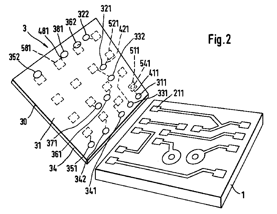
- FIG. 2 is perspective and together with the 1 a first variant of a Adapter arrangement 3 shown.
- a first and a second are on and / or in the film 30 and an nth electrically conductive contact bump 311, 321, 381 arranged. Furthermore, ten further contact bumps 322; 331, 332; 341, 342; 351, 352; 361, 362; 371 available.
- the Reference numerals of the contact bumps are chosen so that their last two digits the last two digits of the Reference numerals of test points 222; 231, 232; 241, 242; 251, 252; 261, 262; 271 are the same.
- the first contact bump 311 On the back of the film 30 is the first contact bump 311 by means of a first conductor track 411 with a first Contact point 511 connected.
- the other conductor lines and no reference numerals assigned to the other contact points are not limited to the other contact points.
- the reference numerals of the conductor tracks are chosen so that their last two digits the last two digits of the Reference numbers for test points 211, 221, 222, 231, 232, 241, 242, 251, 252, 261, 262, 271, 281 and contact bumps 311, 321, 322, 331, 332, 341, 342, 351, 352, 361, 362, 371, 381 are the same.
- the first contact point is 511 with one first contact needle of an input contact field of the Test device, the second contact point 521 with a second Contact pin of the input contact field, the nth Contact point 581 with an nth contact needle and the further contact points of a corresponding one further contact needle of the input contact field electrically to contact.
- the input contact field of the test device has one in lines and Columns regular arrangement of the contact pins mentioned.
- the surface is a mirror image of this arrangement Distribution of the contact points to which the contact points 511, 521, 581 belong.
- the contact bump has a contacting part 3111 and a longitudinal axis 3112. It leads perpendicularly from the Back 32 to front 31 through the film 30 in one Through hole 33, which has a central axis 330.
- Such a contact bump is usually in the bore 33 produces that therein, starting from the Backside 32 existing conductor track 411, galvanic or Electroless copper over the edge at the front 31 bore 33 is grown out.
- This forms a contacting part 3111, the front 31 towered over in one stage and seated in the bore 33 such that the longitudinal axis 3112 coincides with the central axis 330.
- the surface of the contacting part 3111 is one Nickel-gold layer 3113 plated.
- Fig. 3 is also because of the better representation than shown in Fig. 2 that an electrically insulating, resilient intermediate film 34 on the back 32 of the Film 30 is arranged, which e.g. mechanically firm be connected and e.g. made of a suitable foam can exist.
- an electrically insulating, resilient intermediate film 34 on the back 32 of the Film 30 is arranged, which e.g. mechanically firm be connected and e.g. made of a suitable foam can exist.
- the film 30 hugs the pressures mentioned during testing very well to the PCB 1 on, even if they are quite uneven should.
- the first variant of the invention according to FIG. 2 can also be used for double-sided printed circuit boards are used.
- this Case is for the bottom of the two-sided circuit board one corresponding to the adapter arrangement 3 To provide adapter arrangement. This is when testing using one corresponding to the intermediate film 34 Intermediate film to the input contact field of the test device to press.
- the adapter assembly 6 is essentially a single-layer flexible film 60 Insulating material with a front 61 and one Back 62 and with a first part 63 and one with it contiguous second part 64.
- the conductor tracks also extend into the second part 64 the film 60 and end there in associated front side contact points; of these is only that for Fig. 4 Front contact point 652 belonging to contact bump 352 shown.
- the contacting is done by the second part 64 of the Foil 60 is turned by about 180 ° and by that Input contact field on the front 61 of the film 60 in second part 64 pressed, with an intermediate layer an electrically insulating, resilient Intermediate film 74 between the first part 63 and the second part 64 of the rear side 62 of the film 60.
- the intermediate film 74 is only partial in FIG. 5 shown so that it does not cover other parts of the figure.
- the intermediate film 74 exercises its Bump leveling function both at first Part 63 and the circuit board 1 as well as the second Part 64 and the input contact field.
- the second variant of the invention according to FIG. 4 can also can be used together with double-sided printed circuit boards. This is for the back of the two-sided circuit board another one corresponding to the adapter arrangement 6, provide two-part adapter arrangement. This is with Test by turning 180 ° and using one of the Intermediate film 74 corresponding further intermediate film press the input contact field of the test device.
Landscapes
- Engineering & Computer Science (AREA)
- Microelectronics & Electronic Packaging (AREA)
- Computer Hardware Design (AREA)
- General Engineering & Computer Science (AREA)
- Physics & Mathematics (AREA)
- General Physics & Mathematics (AREA)
- Metallurgy (AREA)
- Manufacturing & Machinery (AREA)
- Testing Of Short-Circuits, Discontinuities, Leakage, Or Incorrect Line Connections (AREA)
Abstract
Diese Adapteranordnungen (3, 6) sind zum Testen von auch
großflächigen, Leiterplatten (1) geeignet, deren n
Testpunkte (211 ... 281) nur einen Abstand von etwa 150 µm
haben können. Eine einschichtige flexible Folie (30) aus
Isoliermaterial hat n Kontaktbumps (311 ...381) mit einem
Kontaktierungsteil (3111) und einer Längsachse (3112).
Jeder Kontaktbump führt durch die Folie senkrecht hindurch,
überragt die Vorderseite einstufig und sitzt derart in
einer Bohrung, daß die Längsachse mit deren Mittelachse
zusammenfällt. Während des Testens wird jeder Kontaktbump
mit dem zugehörigen Testpunkt durch flächiges Andrücken der
Folie (30) an die Leiterplatte (1) mechanisch in Berührung
gebracht und dadurch elektrisch kontaktiert. Jeweils ein
Leiterzug (411, 421, 481) verläuft auf der Rückseite der
Folie von einem entsprechenden Kontaktbump zu einem
zugehörigen Kontaktpunkt (511, 521, 581). Jeder
Kontaktpunkt ist mit einer entsprechenden Kontaktnadel
eines Eingangskontaktfelds des Testgeräts mittels dessen
Andrückens an die Rückseite der Folie (30) unter
Zwischenlage einer elektrisch isolierenden, elastisch
federnden Zwischenfolie (34) elektrisch kontaktiert, die
dort, wo eine Kontaktnadel einen Kontaktpunkt zu
kontaktieren hat, eine elektrische Durchkontaktierung
aufweist.

Description
Die Erfindung betrifft Adapteranordnungen zum Testen von mindestens einlagigen, unbestückten Leiterplatten.The invention relates to adapter arrangements for testing at least single-layer, bare printed circuit boards.
Nach der Herstellung dieser Leiterplatten, also wenn deren Leiterbahnen fertiggestellt wurden, ist es erforderlich, jede dieser Leiterplatten mindestens in zweierlei Hinsicht elektrisch zu testen. Einerseits ist zu testen, ob Leiterbahnen, die voneinander isoliert sein sollen, auch voneinander isoliert sind und nicht einen unzulässig niederen Isolationswiderstand gegeneinander aufweisen, insb. kurzgeschlossen sind. Andererseits ist zu testen, ob die einzelnen Leiterbahnen auf ihrem Verlauf auch leitend sind und nicht einen unzulässig hohen Widerstand haben, insb. ob sie unterbrochen sind.After the manufacture of these circuit boards, so if theirs Conductor tracks have been completed, it is necessary each of these circuit boards in at least two ways to test electrically. On the one hand, you have to test whether Conductors that should be insulated from each other, too are isolated from each other and not inadmissible have low insulation resistance to each other, especially short-circuited. On the other hand, you have to test whether the individual conductor tracks are also conductive on their course are and do not have an inadmissibly high resistance, especially whether they are interrupted.
Das Testen nach dem Herstellen ist auch in der Halbleiter-Technik üblich und erforderlich, die mit der Technik der Herstellung von Leiterplatten, wenn überhaupt, nur wenig gemeinsam hat. So werden bekanntlich in einem Silicium-Wafer nach der Planartechnik eine Vielzahl von einzelnen integrierten Schaltungen (= Einzel-ICs) dadurch erzeugt, daß im Bereich des jeweiligen Einzel-ICs an seiner Oberfläche mittels Aluminium-Leitbahnen untereinander elektrisch verbundene Halbleiterzonen erzeugt werden.Testing after manufacturing is also in semiconductor technology usual and necessary, which with the technique of Little, if any, manufacture of printed circuit boards has in common. As is well known, in a silicon wafer according to the planar technique a variety of individual integrated circuits (= single ICs) that in the area of the individual IC at its Surface by means of aluminum interconnects electrically connected semiconductor zones are generated.
Die Aluminium-Leitbahnen führen zu am Rand des Einzel-ICs angeordneten Aluminium-Pads. Beim Testen werden auf die Pads harte Spitzen praktisch senkrecht aufgesetzt, die zu federnden, meist schräg zur Oberfläche der Pads gerichteten Kontaktnadeln gehören. Die Kontaktnadeln sind Bestandteil einer Adapteranordnung, die die Kontaktnadeln elektrisch mit einem Meßgerät verbindet. An der Adapteranordnung sind die Kontaktnadeln auf die Pads justierbar gehaltert.The aluminum interconnects lead to the edge of the single IC arranged aluminum pads. When testing on the Pads hard tips placed practically perpendicular to the resilient, usually directed obliquely to the surface of the pads Contact needles belong. The contact needles are part of it an adapter arrangement that electrically the contact needles connects to a measuring device. Are on the adapter assembly the contact needles are adjustable on the pads.
Die Spitzen sind erforderlich, um die an der Oberfläche von Aluminium immer vorhandene Aluminiumoxid-Schicht sicher durchstoßen zu können, da erst dann ein erforderlicher, möglichst niederohmiger Kontakt mit den Pads erreicht wird. Die Adapteranordnung wird zu diesem Zweck solange auf die Pads zu bewegt, bis die schräg gerichteten Kontaktnadeln einen Federdruck auf die Spitzen und die Pads einwirken lassen.The tips are required to be on the surface of Aluminum always present aluminum oxide layer safely to be able to penetrate, because only then a necessary, contact with the pads is as low as possible. The adapter arrangement is for this purpose as long as Pads too moved until the slanted contact pins apply spring pressure to the tips and pads to let.
Zur Vermeidung der genannten, auf die Testpunkte aufzusetzenden Kontaktnadeln ist in der WO-A 96/07924 eine zum Testen von noch nicht von einem Silicium-Wafer abgetrennten Einzel-ICs bestimmte Adapteranordnung beschrieben, wobei das Einzel-IC einen ersten, einen zweiten und einen n-ten auch als Testpunkt dienenden Pad aufweist, wobei die Pads an einem Rand des Einzel-ICs nebeneinanderliegen und wobei n eine beliebig vorgebbare ganze Zahl ist, welche Adapteranordnung umfaßt:
- eine als Membran wirkende, mehrschichtige flexible Folie
aus Isoliermaterial mit
- -- einer Vorder- und einer Rückseite,
- -- einer an der Vorderseite liegenden Vorderseiten-Schicht,
- -- einer an der Rückseite liegenden Rückseiten-Schicht,
- -- einer zwischen der Vorderseiten- und der Rückseiten-Schicht angeordneten Mittelschicht,
- -- einem ersten, einem zweiten und einem n-ten elektrisch
leitenden Kontaktbump mit einer Längsachse und einem
Kontaktierungsteil, der an seinem Ende harte, spitze
Mikrovorsprünge trägt, welcher Kontaktbump
- --- durch die Vorderseiten-Schicht in einer Bohrung, die eine Mittelachse hat, zur Vorderseite senkrecht hindurchführt,
- --- die Vorderseite in zwei Stufen derart überragt,
- ---- daß eine erste Stufe eine seitliche elektrische Verbindung zum Kontaktierungsteil herstellt und
- ---- daß der Kontaktierungsteil gegenüber der Bohrung seitlich versetzt ist,
- --- von welchen Kontaktbumps während des Testens der erste Kontaktbump mit dem ersten Testpunkt, der zweite Kontaktbump mit dem zweiten Testpunkt und der n-te Kontaktbump mit dem n-ten Testpunkt durch flächiges Andrücken der Folie an die Leiterplatte mechanisch in Berührung zu bringen und dadurch elektrisch zu kontaktieren ist,
- -- einer den ersten Kontaktbump kontaktierenden, auf einer von der Vorderseite abgewandten Seite der Vorderseiten-Schicht verlaufenden ersten Leiterbahn,
- -- einer den zweiten Kontaktbump kontaktierenden, auf der von der Vorderseite abgewandten Seite der Vorderseiten-Schicht verlaufenden zweiten Leiterbahn und
- -- einer den n-ten Kontaktbump kontaktierenden, auf der von
der Vorderseite abgewandten Seite der Vorderseiten-Schicht
verlaufenden n-ten Leiterbahn,
- --- von denen die erste Leiterbahn mit einem ersten Kontaktpad, die zweite Leiterbahn mit einem zweiten Kontaktpad und die n-te Leiterbahn mit einem n-ten Kontaktpad dauernd verbunden ist, und
- eine Blattfedervorrichtung,
- -- mit der die Membran über einen Stempel flächig an die Pads gedrückt werden kann und
- -- deren Federkraft einstellbar ist.
- a multi-layer flexible film made of insulating material that acts as a membrane
- - a front and a back,
- - a front layer on the front,
- - a back layer on the back,
- a middle layer arranged between the front and back layers,
- - A first, a second and an n-th electrically conductive contact bump with a longitudinal axis and a contacting part which carries hard, pointed micro-projections at its end, which contact bump
- --- through the front layer in a hole that has a central axis, leads perpendicular to the front,
- --- towering over the front in two stages,
- ---- that a first stage creates a lateral electrical connection to the contacting part and
- ---- that the contacting part is laterally offset from the hole,
- --- which contact bumps mechanically come into contact with during testing the first contact bump with the first test point, the second contact bump with the second test point and the nth contact bump with the nth test point by pressing the film flat against the circuit board and thereby making electrical contact
- a first conductor track contacting the first contact bump and running on a side of the front-side layer facing away from the front,
- a second conductor track contacting the second contact bump and running on the side of the front-side layer facing away from the front and
- an nth conductor track contacting the nth contact bump and running on the side of the front side layer facing away from the front side,
- --- of which the first conductor track is permanently connected to a first contact pad, the second conductor track is connected to a second contact pad and the nth conductor track is connected to an nth contact pad, and
- a leaf spring device,
- - with which the membrane can be pressed flat against the pads using a stamp and
- - whose spring force is adjustable.
Das oben erwähnte Kontaktierungsproblem, eine Aluminiumoxid-Schicht durchstoßen zu müssen, tritt beim Testen von Leiterplatten nicht auf, da bei diesen bekanntlich andere Metalle als Aluminium für die Leiterbahnen, nämlich insb. nickel/gold-, zinn- oder blei/zinn-beschichtetes Kupfer, verwendet werden. Vielmehr ergeben sich beim Testen von Leiterplatten schon aufgrund ihrer gegenüber der Fläche von Einzel-ICs erheblich größeren zu testenden Fläche andere Probleme, die zu lösen sind.The contacting problem mentioned above, one Having to penetrate the aluminum oxide layer occurs Do not test printed circuit boards because of these It is known that other metals than aluminum for the Conductor tracks, namely in particular nickel / gold, tin or lead / tin coated copper can be used. Much more arise when testing printed circuit boards compared to the area of single ICs larger area to be tested other problems to be solved are.
So haben heutige Einzel-ICs eine Fläche von ca. 10 mm mal 10 mm, während Leiterplatten bis zu 400 mm mal 400 mm und mehr groß sein können. Zudem sind Testpunkte, die den erwähnten Pads entsprechen, meist nicht am Rand der Leiterplatte angeordnet, sondern über deren Fläche beliebig verteilt. Auch ist die Anzahl der Testpunkte wesentlich größer als die der Pads von Einzel-ICs.Today's individual ICs have an area of approximately 10 mm 10 mm, while circuit boards up to 400 mm by 400 mm and can be taller. In addition, test points are the mentioned pads correspond, mostly not on the edge of the Printed circuit board arranged, but arbitrarily over its area distributed. The number of test points is also important larger than that of the pads of single ICs.
Ferner sind Leiterplatten aufgrund ihrer großen Flächen über die gesamte Fläche betrachtet erheblich weniger eben als die erwähnten Einzel-ICs und auch nicht verwindungsfrei. Nach einem internationalen Standard (IPC-TM-650; IPC = Institute of Printed Circuits) ist nämlich eine Verwölbung und Verwindung von kleiner als 1,5 % der längsten Abmessung der Leiterplatte zugelassen.Furthermore, circuit boards are due to their large areas Considered considerably less even over the entire area than the single ICs mentioned and neither torsion-free. According to an international standard (IPC-TM-650; IPC = Institute of Printed Circuits) is namely a warping and twisting of less than 1.5% of the longest dimension of the PCB allowed.
Das Aufsetzen von Kontaktnadeln auf Leiterplatten zu deren Testen ist daher praktisch unmöglich. Aber auch die zweistufigen Kontaktbumps nach der oben referierten WO-A 96/07924 sind aus den folgenden Gründen ungeeignet.The placement of contact needles on printed circuit boards to their Testing is therefore practically impossible. But also the two-stage contact bumps after the one referenced above WO-A 96/07924 are unsuitable for the following reasons.
Wegen der erwähnten Unebenheit von Leiterplatten wurden Scherkräfte auf die Kontaktierungsteile der zweistufigen Kontaktbumps einwirken, so daß die ersteren leicht abbrechen könnten. Auch wären wegen der Unebenheit größere Federwege für gleiche Anpreßdrücke an die Leiterplatte als bei der für die sehr gut ebenen Einzel-ICs dimensionierten Adapteranordnung erforderlich. Because of the unevenness of printed circuit boards mentioned Shear forces on the contact parts of the two-stage Contact bumps act so that the former easily could break off. Also would be larger because of the unevenness Travel for the same contact pressure on the PCB as dimensioned for the very well level single ICs Adapter arrangement required.
In den Figuren der JP-A 3 - 237 369 und deren englischem Abstract ist eine Adapteranordnung zum elektrischen Anschluß von zu testenden, mindestens einlagigen, unbestückten Leiterplatten an ein Testgerät beschrieben, die einen ersten, einen zweiten und einen n-ten Testpunkt aufweisen, wobei n eine beliebig vorgebbare ganze Zahl ist, welche Adapteranordnung umfaßt:
- eine einschichtige flexible Folie aus Isoliermaterial
- -- mit einer Vorderseite und einer Rückseite,
- -- mit einem ersten, einem zweiten und einem n-ten
elektrisch leitenden Kontaktbump, der
- --- die Vorderseite einstufig überragt und
- --- zur Rückseite hin durch die Folie hindurch mittels
mehrerer in einem Raster angeordneter, metallgefüllter
Bohrungen und mittels mehreren auf der Rückseite der
Folie verlaufenden Leiterzügen kontaktiert ist,
- ---- von denen je ein Leiterzug zu je einer Bohrung gehört, und
- --- von welchen Kontaktbumps während des Testens der erste Kontaktbump mit dem ersten Testpunkt, der zweite Kontaktbump mit dem zweiten Testpunkt und der n-te Kontaktbump mit dem n-ten Testpunkt durch flächiges Andrücken der Folie an die Leiterplatte mechanisch in Berührung zu bringen und dadurch elektrisch zu kontaktieren ist.
- a single-layer flexible film made of insulating material
- - with a front and a back,
- - With a first, a second and an nth electrically conductive contact bump, the
- --- The front is dominated in one step and
- --- contact is made through the film to the rear by means of several metal-filled holes arranged in a grid and by means of several conductor runs running on the back of the film,
- ---- of which a conductor track belongs to a hole, and
- --- which contact bumps mechanically come into contact with during testing the first contact bump with the first test point, the second contact bump with the second test point and the nth contact bump with the nth test point by pressing the film flat against the circuit board and is to be contacted electrically.
In der EP-A 147 245 ist schließlich eine Adapteranordnung zum elektrischen Anschluß von ausschließlich auf Unterbrechungen von Leiterbahnen zu testenden, mindestens einlagigen, unbestückten Leiterplatten an ein Testgerät beschrieben, die einen ersten, einen zweiten und einen n-ten Testpunkt aufweisen, wobei n eine beliebig vorgebbare ganze Zahl ist, welche Adapteranordnung umfaßt:
- eine einschichtige flexible Folie aus Isoliermaterial
- -- mit einer Vorderseite und einer Rückseite,
- -- mit einem ersten, einem zweiten und einem n-ten
elektrisch leitenden Kontaktbump, der
- --- die Vorderseite einstufig überragt und
- --- zur Rückseite hin durch die Folie hindurch mittels einer einzigen von mehreren in einem Raster angeordneten, metallgefüllten Bohrungen und mittels einer einzigen zugehörigen von mehreren auf der Rückseite der Folie verlaufenden Leiterzügen kontaktiert ist,
- --- von welchen Kontaktbumps während des Testens der erste Kontaktbump mit dem ersten Testpunkt, der zweite Kontaktbump mit dem zweiten Testpunkt und der n-te Kontaktbump mit dem n-ten Testpunkt durch flächiges Andrücken der Folie an die Leiterplatte mechanisch in Berührung zu bringen und dadurch elektrisch zu kontaktieren ist.
- a single-layer flexible film made of insulating material
- - with a front and a back,
- - With a first, a second and an nth electrically conductive contact bump, the
- --- The front is dominated in one step and
- --- is contacted to the rear through the film by means of a single one of a plurality of metal-filled bores arranged in a grid and by means of a single associated one of a plurality of conductor runs running on the back of the film,
- --- which contact bumps mechanically come into contact with during testing the first contact bump with the first test point, the second contact bump with the second test point and the nth contact bump with the nth test point by pressing the film flat against the circuit board and is to be contacted electrically.
Eine Aufgabe der Erfindung besteht daher darin, zum Testen von, insb. auch großflächigen, Leiterplatten geeignete Adapteranordnungen anzugeben, die mit Kontaktbumps das Testen möglich machen, insb. wenn die Mitten der Testpunkte nur einen Abstand von etwa 150 µm haben, welcher Wert die Untergrenze dieser Abstände bei heute herstellbaren Leiterplatten darstellt.An object of the invention is therefore to test of, in particular also large, circuit boards suitable Specify adapter arrangements that with contact bumps Make testing possible, especially when the middle of the test points only have a distance of about 150 µm, which value the Lower limit of these distances with today's producible Represents circuit boards.
Zur Lösung der oben genannten Aufgabe und der oben geschilderten Probleme besteht eine erste Variante der Erfindung in einer Adapteranordnung zum elektrischen Anschluß von zu testenden, mindestens einlagigen, unbestückten Leiterplatten an ein Testgerät, die einen ersten, einen zweiten und einen n-ten Testpunkt aufweisen, wobei n eine beliebig vorgebbare ganze Zahl ist, welche Adapteranordnung umfaßt:
- eine einschichtige flexible Folie aus einem
Isoliermaterial
- -- mit einer Vorder- und einer Rückseite,
- -- mit einem ersten, einem zweiten und einem n-ten
elektrisch leitenden Kontaktbump mit einem
Kontaktierungsteil und einer Längsachse, welcher
Kontaktbump
- --- von der Rückseite zur Vorderseite durch die Folie in einer Bohrung, die eine Mittelachse hat, senkrecht hindurchführt,
- --- die Vorderseite einstufig überragt und
- --- derart in der Bohrung sitzt, daß die Längsachse mit deren Mittelachse zusammenfällt, und
- --- von welchen Kontaktbumps während des Testens der erste Kontaktbump mit dem ersten Testpunkt, der zweite Kontaktbump mit dem zweiten Testpunkt und der n-te Kontaktbump mit dem n-ten Testpunkt durch flächiges Andrücken der Folie an die Leiterplatte mechanisch in Berührung zu bringen und dadurch elektrisch zu kontaktieren ist,
- -- mit einem den ersten Kontaktbump kontaktierenden, auf der Rückseite der Folie verlaufenden ersten Leiterzug,
- -- mit einem den zweiten Kontaktbump kontaktierenden, auf der Rückseite der Folie verlaufenden zweiten Leiterzug,
- -- mit einem den n-ten Kontaktbump kontaktierenden, auf der
Rückseite der Folie verlaufenden n-ten Leiterzug,
- --- von denen der erste Kontaktpunkt mit einer ersten
Kontaktnadel eines Eingangskontaktfelds des
Testgeräts, der zweite Kontaktpunkt mit einer zweiten
Kontaktnadel des Eingangskontaktfelds und der n-te
Kontaktpunkt mit einer n-ten Kontaktnadel des
Eingangskontaktfelds mittels dessen Andrückens an die
Rückseite der Folie unter Zwischenlage einer
elektrisch isolierenden, elastisch federnden
Zwischenfolie elektrisch zu kontaktieren ist,
- ---- die dort, wo eine Kontaktnadel einen Kontaktpunkt zu kontaktieren hat, eine elektrische Durchkontaktierung aufweist.
- a single-layer flexible film made of an insulating material
- - with a front and a back,
- - With a first, a second and an nth electrically conductive contact bump with a contacting part and a longitudinal axis, which contact bump
- --- vertically from the back to the front through the film in a hole that has a central axis,
- --- The front is dominated in one step and
- --- sits in the hole such that the longitudinal axis coincides with its central axis, and
- --- which contact bumps mechanically come into contact with during testing the first contact bump with the first test point, the second contact bump with the second test point and the nth contact bump with the nth test point by pressing the film flat against the circuit board and thereby making electrical contact
- with a first conductor track contacting the first contact bump and running on the back of the film,
- with a second conductor track contacting the second contact bump and running on the back of the film,
- with an nth conductor track contacting the nth contact bump and running on the back of the film,
- --- of which the first contact point with a first contact needle of an input contact field of the test device, the second contact point with a second contact needle of the input contact field and the nth contact point with an nth contact needle of the input contact field by pressing it against the back of the film with an intermediate layer an electrically insulating, resilient intermediate film is to be electrically contacted,
- ---- which has an electrical through connection where a contact needle has to contact a contact point.
Zur Lösung der oben genannten Aufgabe und der oben geschilderten Probleme besteht eine zweite Variante der Erfindung in einer Adapteranordnung zum elektrischen Anschluß von zu testenden, mindestens einlagigen, unbestückten Leiterplatten an ein Testgerät, die einen ersten, einen zweiten und einen n-ten Testpunkt aufweisen, wobei n eine beliebig vorgebbare ganze Zahl ist, welche Adapteranordnung umfaßt:
- eine einschichtige flexible Folie aus einem
Isoliermaterial
- -- mit einer Vorder- und einer Rückseite sowie mit einem ersten und einem damit zusammenhängenden zweiten Teil,
- -- mit einem ersten, einem zweiten und einem n-ten
elektrisch leitenden Kontaktbump mit einem
Kontaktierungsteil und einer Längsachse, welcher
Kontaktbump
- --- im ersten Teil der Folie angeordnet ist,
- --- von der Rückseite zur Vorderseite durch die Folie in einer Bohrung, die eine Mittelachse hat, senkrecht hindurchführt,
- --- die Vorderseite einstufig überragt und
- --- derart in der Bohrung sitzt, daß die Längsachse mit deren Mittelachse zusammenfällt, und
- --- von welchen Kontaktbumps während des Testens der erste Kontaktbump mit dem ersten Testpunkt, der zweite Kontaktbump mit dem zweiten Testpunkt und der n-te Kontaktbump mit dem n-ten Testpunkt durch flächiges Andrücken der Folie an die Leiterplatte mechanisch in Berührung zu bringen und dadurch elektrisch zu kontaktieren ist,
- -- mit einem den ersten Kontaktbump kontaktierenden, auf der Rückseite der Folie verlaufenden ersten Leiterzug,
- -- mit einem den zweiten Kontaktbump kontaktierenden, auf der Rückseite der Folie verlaufenden zweiten Leiterzug,
- -- mit einem den n-ten Kontaktbump kontaktierenden, auf der
Rückseite der Folie verlaufenden n-ten Leiterzug, von
denen
- --- der erste Leiterzug bis zu einem ersten, im zweiten Teil der Folie liegenden Vorderseiten-Kontaktpunkt führt und mit diesem durch die Folie hindurch kontaktiert ist,
- --- der zweite Leiterzug bis zu einem zweiten, im zweiten Teil der Folie liegenden Vorderseiten-Kontaktpunkt führt und mit diesem durch die Folie hindurch kontaktiert ist, und
- --- der n-te Leiterzug zu bis einem n-ten, im zweiten Teil
der Folie liegenden Vorderseiten-Kontaktpunkt führt
und mit diesem durch die Folie hindurch kontaktiert
ist, wobei
- ---- der erste Vorderseiten-Kontaktpunkt mit einer ersten Kontaktnadel eines Eingangskontaktfelds des Testgeräts, der zweite Vorderseiten-Kontaktpunkt mit einer zweiten Kontaktnadel des Eingangskontaktfelds und der n-te Vorderseiten-Kontaktpunkt mit einer n-ten Kontaktnadel des Eingangskontaktfelds durch Wenden des zweiten Teils der Folie um ca. 180° und mittels Andrückens des Eingangskontaktfelds an die Vorderseite der Folie im zweiten Teil unter Zwischenlage einer elektrisch isolierenden, elastisch federnden Zwischenfolie zwischen die Rückseite der Folie in deren erstem und zweitem Teil elektrisch zu kontaktieren ist.
- a single-layer flexible film made of an insulating material
- - with a front and a back as well as with a first and a related second part,
- - With a first, a second and an nth electrically conductive contact bump with a contacting part and a longitudinal axis, which contact bump
- --- is arranged in the first part of the slide,
- --- vertically from the back to the front through the film in a hole that has a central axis,
- --- The front is dominated in one step and
- --- sits in the hole such that the longitudinal axis coincides with its central axis, and
- --- which contact bumps mechanically come into contact with during testing the first contact bump with the first test point, the second contact bump with the second test point and the nth contact bump with the nth test point by pressing the film flat against the circuit board and thereby making electrical contact
- with a first conductor track contacting the first contact bump and running on the back of the film,
- with a second conductor track contacting the second contact bump and running on the back of the film,
- - With an nth conductor track contacting the nth contact bump and running on the back of the film, of which
- --- the first conductor path leads to a first front-side contact point located in the second part of the film and is contacted with it through the film,
- --- the second conductor path leads to a second front contact point located in the second part of the film and is contacted with it through the film, and
- --- the nth conductor path leads to an nth front contact point located in the second part of the film and is contacted with it through the film, whereby
- ---- the first front side contact point with a first contact needle of an input contact field of the test device, the second front side contact point with a second contact needle of the input contact field and the nth front side contact point with an nth contact needle of the input contact field by turning the second part the film by about 180 ° and by pressing the input contact field to the front of the film in the second part with the interposition of an electrically insulating, resilient intermediate film between the back of the film in the first and second part is to be contacted electrically.
Nach einer bevorzugten Ausgestaltung der ersten Variante der Erfindung sind die Durchkontaktierungen in Form von in Längsrichtung federnden Stiften oder in Form von elastischen leitenden Zylindern realisiert. According to a preferred embodiment of the first variant of the invention are the vias in the form of Longitudinal resilient pins or in the form of realized elastic conductive cylinders.
Ein Vorteil der Erfindung besteht darin, daß eine speziell für das Testen von Leiterplatten geeignete Adapteranordnung geschaffen wird, die alle an sie zu stellenden Anforderungen erfüllt und leicht mit den in der Leiterplattentechnik üblichen Verfahren herstellbar, also mit dieser Technik kompatibel ist.An advantage of the invention is that one specifically adapter arrangement suitable for testing printed circuit boards is created, all to be put to them Requirements met and easy with those in the Printed circuit board technology can be produced, so is compatible with this technology.
Ein weiterer Vorteil ist, daß die Adapteranordnung der Erfindung aufgrund ihres Aufbaus auch bei doppelseitigen Leiterplatten ohne weiteres verwendet werden kann, wie unten noch ausführlich erläutert werden wird.Another advantage is that the adapter arrangement Invention due to its structure even with double-sided Printed circuit boards can be used easily, such as will be explained in detail below.
Die Erfindung und weitere Vorteile werden nun anhand von Ausführungsbeispielen näher erläutert, die in den Figuren der Zeichnung schematisch dargestellt sind; dabei sind Bezugszeichen, die anhand einer bestimmten Figur erläutert wurden, in folgenden Figuren nur noch wenn erforderlich wieder eingetragen.
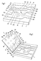
- Fig. 1
- zeigt perspektivisch eine Leiterplatte mit einem einfachen Layout,
- Fig. 2
- zeigt perspektivisch eine Adapteranordnung entsprechend einer ersten Variante der Erfindung zusammen mit der Leiterplatte von Fig. 1,
- Fig. 3
- zeigt im Schnitt einen Kontaktbump der Adapteranordnung, und
- Fig. 4
- zeigt perspektivisch eine Adapteranordnung entsprechend einer zweiten Variante der Erfindung zusammen mit der Leiterplatte von Fig. 1.
- Fig. 1
- shows in perspective a circuit board with a simple layout,
- Fig. 2
- shows in perspective an adapter arrangement according to a first variant of the invention together with the circuit board of FIG. 1,
- Fig. 3
- shows in section a contact bump of the adapter assembly, and
- Fig. 4
- shows in perspective an adapter arrangement according to a second variant of the invention together with the circuit board of FIG. 1.
In Fig. 1 ist eine noch nicht mit elektronischen
Komponenten bestückte Leiterplatte 1, die im eingangs
erwähnten Sinn getestet werden muß, mit einem einfachen
Layout perspektivisch gezeigt. Die Leiterplatte 1 hat eine
nicht zu sehende Unterseite und eine Oberseite 11 und ist
darauf mit acht Leiterbahnen 21, 22, 23, 24, 25, 26, 27, 28
versehen.In Fig. 1 one is not yet electronic
Components populated
Die Leiterbahn 21 ist somit eine erste Leiterbahn, die
Leiterbahn 22 eine zweite Leiterbahn und die Leiterbahn 28
eine m-te Leiterbahn. Von diesen Leiterbahnen mündet die
Leiterbahn 21 in die Leiterbahn 22, während die restlichen
miteinander nicht verbundene selbständige Leiterbahnen
sind. Es sind somit in Fig. 1 m = 8 Leiterbahnen vorhandenThe
Die Leiterbahn 21 ist an ihrem einzigen Ende mit einem
ersten Testpunkt 211 und die Leiterbahn 22 an ihrem einen
Ende mit einem zweiten Testpunkt 221 versehen. Ein weiterer
Testpunkt 222 befindet sich am anderen Ende der Leiterbahn
22; weitere Testpunkte 231, 232; 241, 242; 251, 252; 261,
262 befinden sich an den Enden der Leiterbahnen 23, 24, 25,
26. Die Leiterbahnen 27, 28 haben jeweils nur einen
Testpunkt 271, 281; der Testpunkt 281 ist ein n-ter
Testpunkt. Alle diese Testpunkte sind in Fig. 1 rechteckig
dargestellt. In Fig. 1 sind n = 13 Testpunkte vorhanden.The
Ferner sind noch zwei kreisförmige Anschlußflächen 273, 283
gezeigt, über die durch die Leiterplatte hindurch die
elektrische Verbindung zu eventuell vorhandenen, nicht zu
sehenden Leiterbahnen auf der Unterseite der Leiterplatte 1
hergestellt werden kann. Das ist z.B. durch vom Hersteller
der Leiterplatte bereits erzeugte Durchmetallisierungen
oder erst vom Anwender der Leiterplatte mittels einer
einzulötenden Komponente relisierbar. There are also two circular connection surfaces 273, 283
shown, through which through the circuit board
electrical connection to any existing, not to
seeing conductor tracks on the underside of the
An mindestens einem Teil der Testpunkte werden vom Benutzer
der Leiterplatte nach deren Auslieferung elektronische
Komponenten, wie z.B. MELF- oder MiniMELF-Komponenten
angebracht. Die Leiterplatte 1 ist in Fig. 1 einlagig
dargestellt, was jedoch nicht zwingend ist.At least part of the test points are created by the user
the printed circuit board after delivery electronic
Components such as MELF or MiniMELF components
appropriate. The
Die Testpunkte sind während des Testvorgangs mittels einer Adapteranordnung an ein nicht dargestelltes Testgerät anzuschließen, das von üblicher Bauart ist, so daß auf seine Darstellung und Erläuterung hier verzichtet werden kann.The test points are during the test process using a Adapter arrangement to a test device, not shown to connect, which is of conventional design, so that its presentation and explanation are omitted here can.
In Fig. 2 ist perspektivisch und zusammen mit der
Leiterplatte 1 von Fig. 1 eine erste Variante einer
Adapteranordnung 3 dargestellt. Diese umfaßt eine
einschichtige flexible Folie 30 aus Isoliermaterial, z.B.
aus einem Polyimid, die eine Vorderseite 31 und eine nur in
Fig. 3 zu sehende Rückseite 32 hat.2 is perspective and together with the
1 a first variant of a
Auf und/oder in der Folie 30 sind ein erster, ein zweiter
und ein n-ter elektrisch leitender Kontaktbump 311, 321,
381 angeordnet. Ferner sind zehn weitere Kontaktbumps 322;
331, 332; 341, 342; 351, 352; 361, 362; 371 vorhanden. Die
Bezugszeichen der Kontaktbumps sind so gewählt, daß ihre
letzten beiden Ziffern den letzten beiden Ziffern der
Bezugszeichen der Testpunkte 222; 231, 232; 241, 242; 251,
252; 261, 262; 271 gleich sind.A first and a second are on and / or in the
Alle n = 13 Kontaktbumps sind auf der Vorderseite 31 der
Folie 30 genau spiegelbildlich zu der flächenmäßigen
Anordnung der n = 13 Testpunkte auf der Leiterplatte 1
angeordnet. Wenn während des Testens die Vorderseite 31 der
Folie 3 mit der Oberseite 11 der Leiterplatte 1 durch
Auflegen mechanisch in Berührung gebracht und nach einem
entsprechenden Ausrichten flächig, z.B. mittels eines
Stempels, daran angedrückt wird, kontaktieren die
"zueinander gehörenden" Kontaktbumps "ihre" Testpunkte
elektrisch.All n = 13 contact bumps are on the
Auf der Rückseite der Folie 30 ist der erste Kontaktbump
311 mittels eines ersten Leiterzugs 411 mit einem ersten
Kontaktpunkt 511 verbunden. In gleicher Weise sind der
zweite Kontaktbump 321, der n-te Kontaktbump 381 und die
weiteren Kontaktbumps 322; 331, 332; 341, 342; 351, 352;
361, 362; 371 über einen zweiten Leiterzug 421 bzw. einen
n-ten Leiterzug 481 bzw. weitere Leiterzüge mit einem
zweiten Kontaktpunkt 521 bzw. einem n-ten Kontaktpunkt 581
bzw. mit weiteren Kontaktpunkten verbunden. Der
Übersichtlichkeit halber sind den weiteren Leiterzügen und
den weiteren Kontaktpunkten keine Bezugszeichen zugeordnet.On the back of the
Die Bezugszeichen der Leiterzüge sind so gewählt, daß ihre
letzten beiden Ziffern den letzten beiden Ziffern der
Bezugszeichen der Testpunkte 211, 221 222, 231, 232, 241,
242, 251, 252, 261, 262, 271, 281 und der Kontaktbumps 311,
321, 322, 331, 332, 341, 342, 351, 352, 361, 362, 371, 381
gleich sind.The reference numerals of the conductor tracks are chosen so that their
last two digits the last two digits of the
Reference numbers for
Beim Testen sind der erste Kontaktpunkt 511 mit einer
ersten Kontaktnadel eines Eingangskontaktfelds des
Testgeräts, der zweite Kontaktpunkt 521 mit einer zweiten
Kontaktnadel des Eingangskontaktfelds, der n-te
Kontaktpunkt 581 mit einer n-ten Kontaktnadel und die
weiteren Kontaktpunkte von jeweils einer entsprechenden
weiteren Kontaktnadel des Eingangskontaktfelds elektrisch
zu kontaktieren.When testing, the first contact point is 511 with one
first contact needle of an input contact field of the
Test device, the
Dies geschieht dadurch, daß das Eingangskontaktfeld an die
Rückseite 32 der Folie 30 unter Zwischenlage einer
elektrisch isolierenden, elastisch federnden Zwischenfolie
34 gedrückt wird. Diese ist dort, wo eine Kontaktnadel
einen Kontaktpunkt zu kontaktieren hat, mit einer
elektrischen Durchkontaktierung 541 versehen.This happens because the input contact field to the
Das in Fig. 2 der Einfachheit halber nicht dargestellte Eingangskontaktfeld des Testgeräts hat eine in Zeilen und Spalten regelmäßige Anordnung der erwähnten Kontaktnadeln. Zu dieser Anordnung spiegelbildlich ist die flächenmäßige Verteilung der Kontaktpunkte, zu denen die Kontaktpunkte 511, 521, 581 gehören.This is not shown in Fig. 2 for the sake of simplicity The input contact field of the test device has one in lines and Columns regular arrangement of the contact pins mentioned. The surface is a mirror image of this arrangement Distribution of the contact points to which the contact points 511, 521, 581 belong.
Die Fig. 3 zeigt den Aufbau der Kontaktbumps im Schnitt und
stark vergrößert, und zwar anhand des Kontaktbumps 311 von
Fig. 2. Der Kontaktbump hat einen Kontaktierungsteil 3111
sowie eine Längsachse 3112. Er führt senkrecht von der
Rückseite 32 zur Vorderseite 31 durch die Folie 30 in einer
Bohrung 33 hindurch, die eine Mittelachse 330 hat.3 shows the structure of the contact bumps in section and
greatly enlarged, based on the
Üblicherweise wird ein derartiger Kontaktbump dadurch in
der Bohrung 33 erzeugt, daß darin, ausgehend vom an der
Rückseite 32 vorhandenen Leiterzug 411, galvanisch oder
außenstromlos Kupfer über den Rand an der Vorderseite 31
der Bohrung 33 hinaus wachsen gelassen wird. Dadurch bildet
sich ein Kontaktierungsteil 3111, der die Vorderseite 31
einstufig überragt und derart in der Bohrung 33 sitzt, daß
die Längsachse 3112 mit der Mittelachse 330 zusammenfällt.
Die Oberfläche des Kontaktierungsteils 3111 ist mit einer
Nickel-Gold-Schicht 3113 plattiert.Such a contact bump is usually in
the
In Fig. 3 ist ferner wegen der besseren Darstellbarkeit als
in Fig. 2 gezeigt, daß eine elektrisch isolierende,
elastisch federnde Zwischenfolie 34 an der Rückseite 32 der
Folie 30 angeordnet ist, die dort z.B. mechanisch fest
verbunden sein und z.B. aus einem geeigneten Schaumstoff
bestehen kann. Somit schmiegt sich die Folie 30 beim
erwähnten Andrücken während des Testens sehr gut an die
Leiterplatte 1 an, selbst wenn diese recht uneben sein
sollte.In Fig. 3 is also because of the better representation than
shown in Fig. 2 that an electrically insulating,
resilient
Die erste Variante der Erfindung nach Fig. 2 kann auch bei
zweiseitigen Leiterplatten angewendet werden. In diesem
Fall ist für die Unterseite der zweiseitigen Leiterplatte
eine der Adapteranordnung 3 entsprechende weitere
Adapteranordnung vorzusehen. Diese ist beim Testen mittels
einer der Zwischenfolie 34 entsprechenden weiteren
Zwischenfolie an das Eingangskontaktfeld des Testgeräts
anzudrücken.The first variant of the invention according to FIG. 2 can also be used for
double-sided printed circuit boards are used. In this
Case is for the bottom of the two-sided circuit board
one corresponding to the
Die Fig. 4 zeigt perspektivisch eine Adapteranordnung 6
entsprechend einer zweiten Variante der Erfindung zusammnen
mit der Leiterplatte von Fig. 1. Die Adapteranordnung 6 ist
im wesentlichen eine einschichtige flexible Folie 60 aus
Isoliermaterial mit einer Vorderseite 61 und einer
Rückseite 62 sowie mit einem ersten Teil 63 und einem damit
zusammenhängenden zweiten Teil 64.4 shows an
Auf der Vorderseite 61 sind im ersten Teil 63 wie bei der
Folie 30 von Fig. 2 Kontaktbumps zur Kontaktierung der
Testpunkte der Leiterplatte 1 vorgesehen. Auf der Rückseite
62 sind wieder Leiterzüge vorgesehen, die mit den einzelnen
Kontaktbumps elektrisch verbunden sind. So gehört z.B. der
Kontaktbump 352 zum Leiterzug 452 und zum Testpunkt 252.On the front 61 are in the
Die Leiterzüge erstrecken sich auch in den zweiten Teil 64
der Folie 60 und enden dort in zugehörigen Vorderseiten-Kontaktpunkten;
von diesen ist in Fig. 4 nur der zum
Kontaktbump 352 gehörende Vorderseiten-Kontaktpunkt 652
dargestellt. The conductor tracks also extend into the
Beim Testen werden die einzelnen Vorderseiten-Kontaktpunkte mit einer entsprechenden Kontaktnadel des bereits in Zusammenhang mit Fig. 2 erwähnten Eingangskontaktfelds des Testgeräts elektrisch kontaktiert. Daher ist die fächenmäßige Verteilung der Vorderseiten-Kontaktpunkte auch hier spiegelbildlich zur Anordnung der Kontaktnadeln.When testing, the individual front side contact points with an appropriate contact pin of the already in In connection with Fig. 2 mentioned input contact field of the Test device electrically contacted. Hence the areal distribution of the front-side contact points too here mirror image of the arrangement of the contact needles.
Das Kontaktieren erfolgt, indem der zweite Teil 64 der
Folie 60 um ca. 180° gewendet wird und indem das
Eingangskontaktfeld an die Vorderseite 61 der Folie 60 im
zweiten Teil 64 angedrückt, und zwar unter Zwischenlage
einer elektrisch isolierenden, elastisch federnden
Zwischenfolie 74 zwischen den ersten Teil 63 und den
zweiten Teil 64 der Rückseite 62 der Folie 60.The contacting is done by the
Die Zwischenfolie 74 ist in Fig. 5 nur teilweise
dargestellt, damit sie andere Figurenteile nicht überdeckt.
Bei der Adapteranordnung 6 übt die Zwischenfolie 74 ihre
Unebenheiten ausgleichende Funktion sowohl auf den ersten
Teil 63 und die Leiterplatte 1 als auch auf den zweiten
Teil 64 und das Eingangskontaktfeld aus.The
Auch die zweite Variante der Erfindung nach Fig. 4 kann
zusammen mit zweiseitigen Leiterplatten angewendet werden.
Hierbei ist für die Rückseite der zweiseitigen Leiterplatte
eine der Adapteranordnung 6 entsprechende weitere,
zweiteilige Adapteranordnung vorzusehen. Diese ist beim
Testen durch 180°-Wenden und mittels einer der
Zwischenfolie 74 entsprechenden weiteren Zwischenfolie an
das Eingangskontaktfeld des Testgeräts anzudrücken.The second variant of the invention according to FIG. 4 can also
can be used together with double-sided printed circuit boards.
This is for the back of the two-sided circuit board
another one corresponding to the
Folgende Materialien werden bei der Erfindung bevorzugt verwendet:
- Handelsübliche Polyimidfolie als Material der Folien,
- Kupfer-Folie als Material der Leiterbahnen,
- galvanisch oder außenstromlos abgeschiedenes Kupfer als Metallisierung der Füllung der Bohrungen,
- galvanisch oder außenstromlos abgeschiedenes Nickel/Gold als Material der Kontaktbumps,
- handelsübliche nichtleitende Polymerfolien als Material der Zwischenfolien,
- handelsübliche gefederte Stifte oder flexible Zylinder aus elektrisch leitfähigen elastischen Polymeren als Material der Durchkontaktierungen entsprechend Fig. 2.
- Commercial polyimide film as the material of the films,
- Copper foil as material of the conductor tracks,
- galvanically or electrolessly deposited copper as metallization of the filling of the holes,
- Electrolytically or electrolessly deposited nickel / gold as the material of the contact bumps,
- commercially available non-conductive polymer films as the material of the intermediate films,
- Commercially available spring-loaded pins or flexible cylinders made of electrically conductive elastic polymers as the material of the plated-through holes according to FIG. 2.
Folgende Herstellungsverfahren werden bei der Erfindung bevorzugt verwendet:
- Strukturieren der Bohrungen mittels üblichem Plasmaätzen oder Laserbohren oder Photolithographie,
- Strukturieren der Kontaktbumps und der Leiterbahnen mittels Photolithographie und galvanischer oder außenstromloser Metallisierung.
- Structuring of the holes by means of conventional plasma etching or laser drilling or photolithography,
- Structuring the contact bumps and the conductor tracks using photolithography and galvanic or electroless metallization.
Claims (3)
Priority Applications (1)
| Application Number | Priority Date | Filing Date | Title |
|---|---|---|---|
| EP98116790A EP0902297A3 (en) | 1997-09-11 | 1998-09-05 | Adapter devices for testing printed circuit boards |
Applications Claiming Priority (3)
| Application Number | Priority Date | Filing Date | Title |
|---|---|---|---|
| EP97810646A EP0902296A1 (en) | 1997-09-11 | 1997-09-11 | Adapter devices for testing printed circuit boards |
| EP97810646 | 1997-09-11 | ||
| EP98116790A EP0902297A3 (en) | 1997-09-11 | 1998-09-05 | Adapter devices for testing printed circuit boards |
Publications (2)
| Publication Number | Publication Date |
|---|---|
| EP0902297A2 true EP0902297A2 (en) | 1999-03-17 |
| EP0902297A3 EP0902297A3 (en) | 2001-11-28 |
Family
ID=26148060
Family Applications (1)
| Application Number | Title | Priority Date | Filing Date |
|---|---|---|---|
| EP98116790A Withdrawn EP0902297A3 (en) | 1997-09-11 | 1998-09-05 | Adapter devices for testing printed circuit boards |
Country Status (1)
| Country | Link |
|---|---|
| EP (1) | EP0902297A3 (en) |
Cited By (1)
| Publication number | Priority date | Publication date | Assignee | Title |
|---|---|---|---|---|
| CN112748322A (en) * | 2019-10-31 | 2021-05-04 | 南亚科技股份有限公司 | Test fixture and test assembly |
Family Cites Families (4)
| Publication number | Priority date | Publication date | Assignee | Title |
|---|---|---|---|---|
| US5228189A (en) * | 1988-11-12 | 1993-07-20 | Mania Gmbh & Co. | Adapter arrangement for electrically connecting flat wire carriers |
| US5399982A (en) * | 1989-11-13 | 1995-03-21 | Mania Gmbh & Co. | Printed circuit board testing device with foil adapter |
| JP2733359B2 (en) * | 1989-12-19 | 1998-03-30 | 日東電工株式会社 | Test head structure |
| US5252916A (en) * | 1992-01-27 | 1993-10-12 | Everett Charles Technologies, Inc. | Pneumatic test fixture with springless test probes |
-
1998
- 1998-09-05 EP EP98116790A patent/EP0902297A3/en not_active Withdrawn
Cited By (1)
| Publication number | Priority date | Publication date | Assignee | Title |
|---|---|---|---|---|
| CN112748322A (en) * | 2019-10-31 | 2021-05-04 | 南亚科技股份有限公司 | Test fixture and test assembly |
Also Published As
| Publication number | Publication date |
|---|---|
| EP0902297A3 (en) | 2001-11-28 |
Similar Documents
| Publication | Publication Date | Title |
|---|---|---|
| DE69302400T2 (en) | TEST ARRANGEMENT WITH FILM ADAPTER FOR PCB | |
| EP1484950B1 (en) | Method for electrical connection | |
| DE3639367C2 (en) | ||
| DE69200500T2 (en) | Tiered multi-layer connector plate and manufacturing methods. | |
| DE69011223T2 (en) | Connector assembly with a movable carriage. | |
| DE3634491A1 (en) | CIRCUIT BOARD AND PROBE CABLE ASSEMBLY | |
| EP0838688B1 (en) | Device and procedure for testing printed circuit boards | |
| DE19944980A1 (en) | Encased electrical connection for a connecting structure used for testing, e.g., semiconductor wafer has a holding structure arranged between an elastomeric element and PCB substrate | |
| DE10015744A1 (en) | Contact structure in probe card, has projection made of electrically conducting material provided in contact board to connect contact pad that is in electrical communication with PCB, via contact trace in via hole | |
| DE2525166A1 (en) | CONTACT PROBE DEVICE | |
| DE102009049848A1 (en) | Electrical connection device | |
| DE4129925A1 (en) | COMPONENT TEST PLATE FOR A SEMICONDUCTOR COMPONENT TESTER WITH A RECONFIGURABLE COAXIAL CONNECTING GRID, AND METHOD FOR USE THEREOF | |
| EP0106990A1 (en) | Contacting element for printed circuit boards | |
| DE2453843A1 (en) | CONNECTOR ARRANGEMENT | |
| EP0875767B1 (en) | Device and procedure for testing naked circuit boards | |
| DE69102917T2 (en) | Integrated circuit tester. | |
| EP0902297A2 (en) | Adapter devices for testing printed circuit boards | |
| EP0995235B1 (en) | Contact for very small liaison contacts and method for producing a contact | |
| EP0902296A1 (en) | Adapter devices for testing printed circuit boards | |
| EP1031042B1 (en) | Device for testing printed boards | |
| CH698875B1 (en) | Printed circuit board assembling method for switching device of room apparatus, involves resting head of pin at edge of bore when pin is completely arranged through bore, and soldering head of pin on carrier over solder area | |
| DE60201537T2 (en) | ELECTRICAL CONNECTION ARRANGEMENT FOR ELECTRONIC COMPONENTS | |
| DE10324450A1 (en) | Contacting device for electronic circuit units and manufacturing method | |
| DE3804425C1 (en) | PCB testing arrangement using several pins - forms contact between test pins and board tracks by compression under vacuum of sheets | |
| DE102024204764B4 (en) | Electronic assembly |
Legal Events
| Date | Code | Title | Description |
|---|---|---|---|
| PUAI | Public reference made under article 153(3) epc to a published international application that has entered the european phase |
Free format text: ORIGINAL CODE: 0009012 |
|
| AK | Designated contracting states |
Kind code of ref document: A2 Designated state(s): AT BE CH CY DE DK ES FI FR GB GR IE IT LI LU MC NL PT SE |
|
| AX | Request for extension of the european patent |
Free format text: AL;LT;LV;MK;RO;SI |
|
| PUAL | Search report despatched |
Free format text: ORIGINAL CODE: 0009013 |
|
| AK | Designated contracting states |
Kind code of ref document: A3 Designated state(s): AT BE CH CY DE DK ES FI FR GB GR IE IT LI LU MC NL PT SE |
|
| AX | Request for extension of the european patent |
Free format text: AL;LT;LV;MK;RO;SI |
|
| AKX | Designation fees paid | ||
| REG | Reference to a national code |
Ref country code: DE Ref legal event code: 8566 |
|
| 19U | Interruption of proceedings before grant |
Effective date: 20020401 |
|
| 19W | Proceedings resumed before grant after interruption of proceedings |
Effective date: 20100401 |
|
| RAP1 | Party data changed (applicant data changed or rights of an application transferred) |
Owner name: WUERTH ELEKTRONIK SCHOPFHEIM GMBH & CO. KG |
|
| STAA | Information on the status of an ep patent application or granted ep patent |
Free format text: STATUS: THE APPLICATION IS DEEMED TO BE WITHDRAWN |
|
| 18D | Application deemed to be withdrawn |
Effective date: 20020529 |