EP0902227A1 - Boitier en une pièce d'un collier de serrage à vis - Google Patents
Boitier en une pièce d'un collier de serrage à vis Download PDFInfo
- Publication number
- EP0902227A1 EP0902227A1 EP97115431A EP97115431A EP0902227A1 EP 0902227 A1 EP0902227 A1 EP 0902227A1 EP 97115431 A EP97115431 A EP 97115431A EP 97115431 A EP97115431 A EP 97115431A EP 0902227 A1 EP0902227 A1 EP 0902227A1
- Authority
- EP
- European Patent Office
- Prior art keywords
- housing
- clamp
- edge
- circumferential direction
- walls
- Prior art date
- Legal status (The legal status is an assumption and is not a legal conclusion. Google has not performed a legal analysis and makes no representation as to the accuracy of the status listed.)
- Granted
Links
Images
Classifications
-
- F—MECHANICAL ENGINEERING; LIGHTING; HEATING; WEAPONS; BLASTING
- F16—ENGINEERING ELEMENTS AND UNITS; GENERAL MEASURES FOR PRODUCING AND MAINTAINING EFFECTIVE FUNCTIONING OF MACHINES OR INSTALLATIONS; THERMAL INSULATION IN GENERAL
- F16L—PIPES; JOINTS OR FITTINGS FOR PIPES; SUPPORTS FOR PIPES, CABLES OR PROTECTIVE TUBING; MEANS FOR THERMAL INSULATION IN GENERAL
- F16L33/00—Arrangements for connecting hoses to rigid members; Rigid hose-connectors, i.e. single members engaging both hoses
- F16L33/02—Hose-clips
- F16L33/08—Hose-clips in which a worm coacts with a part of the hose-encircling member that is toothed like a worm-wheel
Definitions
- the invention relates to a one-piece housing a screw thread clamp, with a curved upper housing part to hold the shaft of a clamping screw with head and to support the head on one Opening edge of the upper housing part, with a lower housing part to accommodate one with threaded sections provided end portion of a clamp band under Engagement of the clamping screw thread in the threaded sections and for receiving the other end portion of the Clamp band with a positive connection with a Bottom of the case, and with the side of the bottom curved sidewalls, which in the circumferential direction of the Clamp longer than the floor.
- a known housing of a worm gear clamp of this type which is commercially available and corresponds to DE 39 41 135 C1
- the bottom is slightly radial curved outside, so that it largely the circumferential curvature by means of the clamp on a pipe or pipe socket clamped hose is adapted.
- the invention has for its object a housing of the type mentioned at the outset, the side walls resilient due to higher clamping screw forces without bending sideways.
- this object is achieved in that the case back on both sides one from one to the other other edge of the housing base extending middle Circumferential section longer than this circumferential section is.
- the length of the floor can be in the middle Circumferential area in the circumferential direction of the clamp required minimum length at which the Bottom - if necessary with a slight curvature -
- the hose curvature in the circumferential direction of the Hose even with different hose diameters is largely adapted.
- the other edge the case back also has a trapezoidal cutout has and lying on the side of this edge and converging towards this second walls two more turns of the clamp band on both sides its centerline with a smaller angle the circumferential direction than include the first walls.
- the smaller angle that is on the side of the tension screw head facing away from the second walls enclose with the circumferential direction than the first Walls has the advantage that the second walls are higher Shear force components of the housing base when tensioning the clamp can take up without deforming.
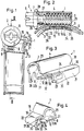
- the worm thread clamp according to FIGS. 1 to 5 from a housing 1, a right-hand clamping screw 2 and a clamp band 3. All three parts consist essentially of steel. Where applicable she galvanized.
- the housing has a curved upper part 4 for receiving of the threaded shaft 5 of the clamping screw 2 and to support the head 6 of the clamping screw on has an opening edge 7 of the upper housing part 4. Furthermore the housing has a lower part 8 for receiving one Threaded portions 9 provided end portion 10 of the Clamp band 3, the clamping screw thread 5 in engages the threaded portions 9, as in Fig. 2nd is shown. Furthermore, the lower housing part 8 the other end section 11 of the clamp band 2 under positive connection to the bottom 12 of the housing 1 on. To form this positive connection the bottom 12 has at each of its axial ends a raised bead 13 or 14, each in a square hole 15 or 16 in a radial direction externally pressed portion of the end portion 11 of the Engage clamp band 3. Holes 15 and 16 are separated by a crosspiece 17 in the end section 11. The threaded sections 9 are in the end section 10 of the clamp band 3 coined.
- the lower part 8 of the housing 1 has on one long side a side arm 18 which the housing 1 against rotation when tightening the right-handed Tensioning screw 2 is supported.
- the boom has an upper one Wall of two overlapping wall sections 19 and 20 and a side wall 21 protruding from the floor 12, the via a bent section 22 in the upper (19) the overlapping wall sections 19, 20 merges.
- the lower wall section 20 of the upper wall of the boom 18 extends with a part 23 through one Section 24 of the bent section 22 and with a Part 25 (Fig. 4) to the inside of the side wall 21.
- Part 23 jumps tongue-like over part 25 in front, is on the outside of the side wall 21, around the axially outer and radially inner edge of the Edge of the cutout 24 bent and ends above of the bottom 12. It lies on the screw head 6 facing Side of the wall section 20 and extends in the circumferential direction of the clamp over the entire Length of the cutout 24.
- the bottom 12 is in the circumferential direction the clamp is shorter than the upper wall 19, 20 and the side wall 21.
- the cutout 24 is in this embodiment one of the lying on the side of the clamping screw head 6 Opening edge of the boom 18 from in the longitudinal direction the bent portion 22 projecting slot, the approximately radially above that facing the screw head 6 Edge of the bottom 12 ends.
- the radially inner in Fig. 1 and 3 lying edge of part 23 is therefore radially outside in the tensioned state of the clamp the circumference of the clamped hose, so that this edge does not cut into the hose material and cannot damage the hose.
- the overlapping wall sections 19, 20 extend over the entire length of the boom 18 tangential to the clamp circumference. But it is also possible the one closer to the screw head, over the length of the cutout 24 extending part of the omit upper wall section 19, so that the Section 24 across the entire width of the lower Wall section 20 to the curved upper housing part 4 extends. Because that part of the wall section 19 bears less to stiffen the housing 1, as below is explained.
- the housing 1 in this case without part 23 would be expanded because if the in particular seized screw 2 a higher one Torque would have to be exerted on the screw 2 in order to loosen them than when the screw is tightened normally.
- the other is that the radially inner edge of the part 23 radially outside the bottom 12 or higher than this lies and the part 23 laterally opposite the Floor 12 is offset in the circumferential direction, ensures that this edge in the tensioned state of the Do not cut the clamp into the hose material and damaged the hose.
- the housing 1 in region of wall 21 not overlapped by part 23 narrower than in the area of part 23, which is confined Installation conditions can play a role.
- the lower wall section of the upper Wall with its bent part close to the radially inner side of the bottom 12 is enough, with a little less Material for the housing. Still has the case a higher strength than this known housing, since the upper wall section 19 compared to this known housing has a higher bending stiffness and with this known housing on the outside the side wall 21 bent part of the lower wall section the top wall of the boom when tensioning and practically not in the tensioned state of the clamp Stiffness of the housing contributes.
- the housing 1 is made of an uncured metal, so that a backstop flap 26, the lower edge of a protruding beyond the bottom 12 Part of the upper housing part 4 on the boom 18 opposite side wall of the housing 1 is trained and initially protrudes downwards, as in Fig. 3 is shown after inserting the screw shaft be bent up into the upper housing part 4 can so that it is in a circumferential groove 27 of the clamping screw 2 engages between head 6 and thread 5, like it is shown in Fig. 2.
- This tab 26 prevents that the clamping screw 12 when opening the Unscrew the screw thread clamp from the housing 1.
- the clamping screw head 6 also engages with a circumferential, formed in one piece with the clamping screw head 6 Flange 28 over the opening edge 7 of the upper housing part 4 away, so that the clamping screw head 6 is supported when tensioning on the upper housing part 4 and in this way additionally the torque mentioned counteracts.
- the bottom 12 of the housing 1 is in the circumferential direction Worm thread clamp, largely according to the Clamp diameter, curved, so that it is largely the Curvature of the hose to be clamped is adjusted and the screw thread clamp in the tightened state a largely uniform contact pressure exercises the entire circumference of the hose to the extent possible tight connection between the hose and the End section of a pipe or pipe socket on which the hose is attached to achieve.
- the housing base 12 in the circumferential direction the clamp is as short as possible so that it can be used without it Having to bend the clamps further, the more the circumferential curvature of hoses with different outside diameters is adjusted because of a worm gear clamp for hoses with different outside diameters can be used.
- a shortening of the case back 12 causes in the circumferential direction of the clamp however at the same time a reduction in the bending stiffness the side walls 21 and 29 around their themselves in the circumferential direction the radially inner bends extending the clamp 30 and 31 when the clamping screw 2 is tightened the entire housing 1 to the right in FIG. 1 relative to the end section 10 of the clamp band 3 on which it strives to roll is to press.
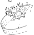
- the edge 32 of the bottom facing the screw head 6 12 is the edge 32 of the bottom facing the screw head 6 12, as FIG. 5 shows more clearly, with an approximately trapezoidal neckline.
- That too Screw head 6 facing edge 33 of the housing base 12 is provided with an approximately trapezoidal cutout, apart from the fact that a relatively short tongue 34 (Fig. 4) in the extension of the bead 14 on the edge 33 in the circumferential direction the clamp protrudes and one edge the opening 16 (FIG. 2) of the inner end portion 11 something spills over.
- the housing base 12 is therefore one on both sides from one edge 32 to the other edge 33 of the housing base 12 extending middle peripheral portion 12a (Fig. 5) longer than this peripheral portion 12a. Accordingly are also the two side walls 21 and 29, in particular the bends 30 and 31, in the circumferential direction the screw thread clamp longer than the floor 12 of the housing 1. As a result, the bending stiffness is also of the side walls 21 and 29 in the area of Bends 30, 31 higher than with an equally short training the bends 30, 31 as the required minimum length of the bottom 12 in the circumferential direction of the clamp, the corresponds to the length of the central section 12a.
- the strength of the housing 1 is higher a lateral bend and / or expansion both when tightening the clamping screw 2 as well as when loosening, the latter when the tension screw 2 after tensioning sits very tight, especially seized Has.
- the risk of expansion of the housing 1 radially outwards be it by a Bending up the lateral peripheral areas of the base 12 or by bending the bends between the upper part of the housing 4 and top wall of the boom 18 and between the top wall and the side wall 21 of the boom 18, significantly reduced.
- the angle ⁇ that the inclined walls 37, 38 with the circumferential direction of the clamp and the center line M of the clamp band 3 is slightly smaller (more acute) than the angle ⁇ that the inclined walls 35, 36 of the clamp band 3 with the circumferential direction of the Include the clamp and the center line M, see Fig. 5.
- This smaller or more acute angle ⁇ that the sloping walls 37, 38 with the circumferential direction of the Include the clamp and the center line M of the clamp band 3 has the advantage that the walls 37, 38 higher Thrust components of the housing base 12 when tensioning the clamp can take up without deforming.
- the angle ⁇ that the walls 35, 36 have with the circumferential direction and include the center line M of the clamp band 3, is largely equal to the angle the sections 32a, 32b of the edge 32 facing them the circumferential direction of the clamp or the center line M of the clamp band 3.
- the edge 32 of the housing base 12 can therefore extend over its entire length Support on the clamp band 3 if the clamping screw 2 is solved. This is particularly advantageous if the clamping screw 2 is very tight in the housing 1, e.g. is stuck.
- the acute angle that the sections 33a, 33b of the edge 33 of the housing base 12 with the circumferential direction of Include the clamp and the center line M of the clamp band 3 is shown somewhat larger than the angle ⁇ , however, it can also be chosen equal to the angle ⁇ be.
- the edge 33 may also be supported on the walls 37, 38 when tightening the clamp.
Landscapes
- Engineering & Computer Science (AREA)
- General Engineering & Computer Science (AREA)
- Mechanical Engineering (AREA)
- Clamps And Clips (AREA)
- Bolts, Nuts, And Washers (AREA)
- Buckles (AREA)
- General Details Of Gearings (AREA)
- Rear-View Mirror Devices That Are Mounted On The Exterior Of The Vehicle (AREA)
Priority Applications (5)
| Application Number | Priority Date | Filing Date | Title |
|---|---|---|---|
| ES97115431T ES2140176T3 (es) | 1997-09-06 | 1997-09-06 | Carcasa de una sola pieza para una abrazadera de rosca helicoidal. |
| EP19970115431 EP0902227B1 (fr) | 1997-09-06 | 1997-09-06 | Boitier en une pièce d'un collier de serrage à vis |
| DE59700767T DE59700767D1 (de) | 1997-09-06 | 1997-09-06 | Einteiliges Gehäuse einer Schneckengewindeschelle |
| ES9801873A ES2132040B1 (es) | 1997-09-06 | 1998-09-04 | Perfeccionamientos en el conjunto de carcasa unipieza y extremo de banda en abrazadera de rosca helicoidal. |
| HK99103689.2A HK1018804B (en) | 1999-08-27 | One-part housing of a screw-type clamp |
Applications Claiming Priority (1)
| Application Number | Priority Date | Filing Date | Title |
|---|---|---|---|
| EP19970115431 EP0902227B1 (fr) | 1997-09-06 | 1997-09-06 | Boitier en une pièce d'un collier de serrage à vis |
Publications (2)
| Publication Number | Publication Date |
|---|---|
| EP0902227A1 true EP0902227A1 (fr) | 1999-03-17 |
| EP0902227B1 EP0902227B1 (fr) | 1999-11-24 |
Family
ID=8227321
Family Applications (1)
| Application Number | Title | Priority Date | Filing Date |
|---|---|---|---|
| EP19970115431 Expired - Lifetime EP0902227B1 (fr) | 1997-09-06 | 1997-09-06 | Boitier en une pièce d'un collier de serrage à vis |
Country Status (3)
| Country | Link |
|---|---|
| EP (1) | EP0902227B1 (fr) |
| DE (1) | DE59700767D1 (fr) |
| ES (2) | ES2140176T3 (fr) |
Families Citing this family (1)
| Publication number | Priority date | Publication date | Assignee | Title |
|---|---|---|---|---|
| ES2156835B1 (es) * | 1999-12-17 | 2002-02-01 | Mikalor Sa | Envolvente-caja mejorada para el tornillo de apriete en abrazaderas. |
Citations (5)
| Publication number | Priority date | Publication date | Assignee | Title |
|---|---|---|---|---|
| GB2150205A (en) * | 1983-11-22 | 1985-06-26 | Takagi Mfg | Worm driven band clamp |
| DE3431751A1 (de) * | 1984-08-29 | 1986-03-13 | Gemi Metallwarenfabrik Gustav Henning KG, 3538 Marsberg | Spannschelle mit spannbandabzug durch eine schnecke sowie verfahren zu deren herstellung |
| US4706346A (en) * | 1984-08-09 | 1987-11-17 | Mikalor, S.A. | Clamping collar |
| DE3941135C1 (en) * | 1989-12-13 | 1991-01-31 | Rasmussen Gmbh, 6457 Maintal, De | Hose clamp with fastening strap with overlapping ends - has clamping leaf spring, curved at less than 180 deg. in relieved state |
| US5473798A (en) * | 1991-05-24 | 1995-12-12 | Pebra Gmbh Paul Braun | Hose clip |
Family Cites Families (4)
| Publication number | Priority date | Publication date | Assignee | Title |
|---|---|---|---|---|
| ES276320Y (es) * | 1983-12-14 | 1987-06-01 | Garcia Puerta Alberto | Abrazadera de husillo perfeccionada |
| ES2011648A6 (es) * | 1987-10-09 | 1990-02-01 | Mikalor Sa | Mejoras introducidas en los puentes de engarce de las semibases del tornillo presionador en el extremo de bridas constrenidoras. |
| DE19546077A1 (de) * | 1995-12-11 | 1997-06-12 | Rasmussen Gmbh | Einteiliges Gehäuse einer Schneckengewindeschelle |
| DE19633435C1 (de) * | 1996-08-20 | 1998-02-12 | Rasmussen Gmbh | Schneckengewindeschelle |
-
1997
- 1997-09-06 DE DE59700767T patent/DE59700767D1/de not_active Expired - Lifetime
- 1997-09-06 EP EP19970115431 patent/EP0902227B1/fr not_active Expired - Lifetime
- 1997-09-06 ES ES97115431T patent/ES2140176T3/es not_active Expired - Lifetime
-
1998
- 1998-09-04 ES ES9801873A patent/ES2132040B1/es not_active Expired - Lifetime
Patent Citations (5)
| Publication number | Priority date | Publication date | Assignee | Title |
|---|---|---|---|---|
| GB2150205A (en) * | 1983-11-22 | 1985-06-26 | Takagi Mfg | Worm driven band clamp |
| US4706346A (en) * | 1984-08-09 | 1987-11-17 | Mikalor, S.A. | Clamping collar |
| DE3431751A1 (de) * | 1984-08-29 | 1986-03-13 | Gemi Metallwarenfabrik Gustav Henning KG, 3538 Marsberg | Spannschelle mit spannbandabzug durch eine schnecke sowie verfahren zu deren herstellung |
| DE3941135C1 (en) * | 1989-12-13 | 1991-01-31 | Rasmussen Gmbh, 6457 Maintal, De | Hose clamp with fastening strap with overlapping ends - has clamping leaf spring, curved at less than 180 deg. in relieved state |
| US5473798A (en) * | 1991-05-24 | 1995-12-12 | Pebra Gmbh Paul Braun | Hose clip |
Also Published As
| Publication number | Publication date |
|---|---|
| DE59700767D1 (de) | 1999-12-30 |
| ES2140176T3 (es) | 2000-02-16 |
| HK1018804A1 (en) | 2000-01-07 |
| ES2132040A1 (es) | 1999-08-01 |
| ES2132040B1 (es) | 2001-03-16 |
| EP0902227B1 (fr) | 1999-11-24 |
Similar Documents
| Publication | Publication Date | Title |
|---|---|---|
| DE3017666A1 (de) | Schlauchklemme | |
| EP1070217B1 (fr) | Configuration de liaison des deux extremites d'une bande, par exemple, d'un anneau ou d'une bague de serrage | |
| EP0936393A2 (fr) | Disposition d'un collier de serrage | |
| WO1998048206A1 (fr) | Bride pour tuyaux | |
| EP0779464B1 (fr) | Boíte unique pour un collier de serrage à vis tangente | |
| CH670869A5 (fr) | ||
| DE3017667A1 (de) | Mechanische verriegelung einer klemme | |
| EP2267237A2 (fr) | Dispositif de fixation | |
| DE69608320T2 (de) | Rohrschelle | |
| DE2854676A1 (de) | Schneckengewindeschelle | |
| DE2800824A1 (de) | Schneckengewindeschelle | |
| CH670293A5 (fr) | ||
| DE2321814A1 (de) | Schlauchklemme | |
| DE19633435C1 (de) | Schneckengewindeschelle | |
| DE2342352C3 (de) | U-Bolzen-Klemmverbindung | |
| EP0769647A1 (fr) | Collier de serrage pour la fixation d'un tuyau | |
| DE102007058319B4 (de) | Schneckengewindeschelle | |
| DE2506589C3 (de) | Schneckengewindeschelle | |
| EP0902227B1 (fr) | Boitier en une pièce d'un collier de serrage à vis | |
| DE60007247T2 (de) | Klammer mit Schraubbefestigung für Förderband | |
| DE2834046A1 (de) | Schraublose bandschelle | |
| DE19835320B4 (de) | Rohrschelle | |
| DE3326070C2 (de) | Breitbandschelle für Rohre oder dergleichen | |
| DE3403781C2 (de) | Breitbandschelle | |
| DE4027032C1 (fr) |
Legal Events
| Date | Code | Title | Description |
|---|---|---|---|
| GRAG | Despatch of communication of intention to grant |
Free format text: ORIGINAL CODE: EPIDOS AGRA |
|
| GRAG | Despatch of communication of intention to grant |
Free format text: ORIGINAL CODE: EPIDOS AGRA |
|
| GRAH | Despatch of communication of intention to grant a patent |
Free format text: ORIGINAL CODE: EPIDOS IGRA |
|
| GRAH | Despatch of communication of intention to grant a patent |
Free format text: ORIGINAL CODE: EPIDOS IGRA |
|
| PUAI | Public reference made under article 153(3) epc to a published international application that has entered the european phase |
Free format text: ORIGINAL CODE: 0009012 |
|
| 17P | Request for examination filed |
Effective date: 19980402 |
|
| AK | Designated contracting states |
Kind code of ref document: A1 Designated state(s): AT BE CH DE DK ES FI FR GB GR IE IT LI LU MC NL PT SE |
|
| GRAA | (expected) grant |
Free format text: ORIGINAL CODE: 0009210 |
|
| AK | Designated contracting states |
Kind code of ref document: B1 Designated state(s): DE ES FR GB |
|
| AKX | Designation fees paid |
Free format text: DE ES FR GB |
|
| REF | Corresponds to: |
Ref document number: 59700767 Country of ref document: DE Date of ref document: 19991230 |
|
| GBT | Gb: translation of ep patent filed (gb section 77(6)(a)/1977) |
Effective date: 19991223 |
|
| REG | Reference to a national code |
Ref country code: IE Ref legal event code: FG4D Free format text: GERMAN |
|
| REG | Reference to a national code |
Ref country code: ES Ref legal event code: FG2A Ref document number: 2140176 Country of ref document: ES Kind code of ref document: T3 |
|
| ET | Fr: translation filed | ||
| REG | Reference to a national code |
Ref country code: IE Ref legal event code: FD4D |
|
| PLBE | No opposition filed within time limit |
Free format text: ORIGINAL CODE: 0009261 |
|
| STAA | Information on the status of an ep patent application or granted ep patent |
Free format text: STATUS: NO OPPOSITION FILED WITHIN TIME LIMIT |
|
| 26N | No opposition filed | ||
| REG | Reference to a national code |
Ref country code: GB Ref legal event code: IF02 |
|
| PGFP | Annual fee paid to national office [announced via postgrant information from national office to epo] |
Ref country code: FR Payment date: 20050819 Year of fee payment: 9 |
|
| PGFP | Annual fee paid to national office [announced via postgrant information from national office to epo] |
Ref country code: ES Payment date: 20050825 Year of fee payment: 9 |
|
| PGFP | Annual fee paid to national office [announced via postgrant information from national office to epo] |
Ref country code: GB Payment date: 20050905 Year of fee payment: 9 |
|
| GBPC | Gb: european patent ceased through non-payment of renewal fee |
Effective date: 20060906 |
|
| REG | Reference to a national code |
Ref country code: FR Ref legal event code: ST Effective date: 20070531 |
|
| PG25 | Lapsed in a contracting state [announced via postgrant information from national office to epo] |
Ref country code: GB Free format text: LAPSE BECAUSE OF NON-PAYMENT OF DUE FEES Effective date: 20060906 |
|
| REG | Reference to a national code |
Ref country code: ES Ref legal event code: FD2A Effective date: 20060907 |
|
| PG25 | Lapsed in a contracting state [announced via postgrant information from national office to epo] |
Ref country code: ES Free format text: LAPSE BECAUSE OF NON-PAYMENT OF DUE FEES Effective date: 20060907 |
|
| PG25 | Lapsed in a contracting state [announced via postgrant information from national office to epo] |
Ref country code: FR Free format text: LAPSE BECAUSE OF NON-PAYMENT OF DUE FEES Effective date: 20061002 |
|
| PGFP | Annual fee paid to national office [announced via postgrant information from national office to epo] |
Ref country code: DE Payment date: 20130918 Year of fee payment: 17 |
|
| REG | Reference to a national code |
Ref country code: DE Ref legal event code: R119 Ref document number: 59700767 Country of ref document: DE Ref country code: DE Ref legal event code: R082 Ref document number: 59700767 Country of ref document: DE |
|
| PG25 | Lapsed in a contracting state [announced via postgrant information from national office to epo] |
Ref country code: DE Free format text: LAPSE BECAUSE OF NON-PAYMENT OF DUE FEES Effective date: 20150401 |