EP0901927B1 - Trappe d'obturation pour couvrir la tubulure de remplissage pour véhicules automobiles - Google Patents
Trappe d'obturation pour couvrir la tubulure de remplissage pour véhicules automobiles Download PDFInfo
- Publication number
- EP0901927B1 EP0901927B1 EP98113978A EP98113978A EP0901927B1 EP 0901927 B1 EP0901927 B1 EP 0901927B1 EP 98113978 A EP98113978 A EP 98113978A EP 98113978 A EP98113978 A EP 98113978A EP 0901927 B1 EP0901927 B1 EP 0901927B1
- Authority
- EP
- European Patent Office
- Prior art keywords
- fuel tank
- inlet cover
- tank inlet
- bearing arm
- alignment marks
- Prior art date
- Legal status (The legal status is an assumption and is not a legal conclusion. Google has not performed a legal analysis and makes no representation as to the accuracy of the status listed.)
- Expired - Lifetime
Links
Images
Classifications
-
- B—PERFORMING OPERATIONS; TRANSPORTING
- B60—VEHICLES IN GENERAL
- B60K—ARRANGEMENT OR MOUNTING OF PROPULSION UNITS OR OF TRANSMISSIONS IN VEHICLES; ARRANGEMENT OR MOUNTING OF PLURAL DIVERSE PRIME-MOVERS IN VEHICLES; AUXILIARY DRIVES FOR VEHICLES; INSTRUMENTATION OR DASHBOARDS FOR VEHICLES; ARRANGEMENTS IN CONNECTION WITH COOLING, AIR INTAKE, GAS EXHAUST OR FUEL SUPPLY OF PROPULSION UNITS IN VEHICLES
- B60K15/00—Arrangement in connection with fuel supply of combustion engines or other fuel consuming energy converters, e.g. fuel cells; Mounting or construction of fuel tanks
- B60K15/03—Fuel tanks
- B60K15/04—Tank inlets
- B60K15/05—Inlet covers
- B60K2015/0507—Arrangements for adjusting the inlet cover
Definitions
- the invention relates to a fuel filler flap for motor vehicles, which in its closed position a trough receiving a tank filler neck in the Vehicle body covered and around in the area of one edge of the Body trough arranged axis is pivotally articulated, the articulation the fuel filler flap one to be attached to the vehicle body Bearing block and a pivotable on this by means of a hinge pin mounted bearing arm that supports the tank flap and one bearing arm encompassing compression spring supported against the body and wherein the tank flap is releasably attached to the bearing arm.
- the invention is therefore based on the object of a tank flap at the beginning to further improve the designated design for motor vehicles, that with the least amount of assembly time even with tank flaps, their Swivel bearing very close to the gap between the body and the tank flap is a perfect painting of the vehicle body allows becomes.
- this object is essentially achieved in that a device is provided for at least one alignment mark arranged on the tank flap and cooperating with a complementary counterpart on the bearing arm, for repeatable fastening of the tank flap to the bearing arm in the correct position.
- certain and preferred embodiment of the invention further provides that the releasable attachment of the fuel filler flap to the bearing arm is vertical aligned to the level of the fuel filler flap, permanently connected to the fuel filler flap Fastener includes.
- the fuel filler flap after painting in a perpendicular to the plane of the surrounding body wall aligned direction of movement connected to the bearing arm is so that when painting on the tank flap and the bearing arm applied layers of paint at most for a slight change the alignment of the tank flap with the surrounding body surface, under no circumstances to an asymmetrical or one-sided change of the circumferential gap between the body recess and the tank flap being able to lead. Because with a parallel position a slight change in the altitude the fuel filler flap to the surrounding body surface hardly looks is noticeable, forms the preferred embodiment of the invention an optimal solution to the problems outlined above.
- a less complex and easy to assemble design form Fastening device for the tank flap on the bearing arm consists in that the releasable attachment of the tank flap on the one hand has a bore recess in the bearing arm and on the other hand one perpendicular to the plane of the Aligned fuel filler flap, with threaded stud attached to it related mother includes.
- the fastening device also by any other for arrangement in a perpendicular to the plane the tank flap aligned position formed suitable fastener his.
- Position on the bearing arm basically includes one to the fastener parallel alignment interacting elements, in particular Alternating projections on the tank flap and bearing arm and recesses, but otherwise can be any suitable shape exhibit.
- the device for repeatable fixing of the fuel filler flap to the bearing arm comprises a total of three alignment marks, the total of three Alignment marks preferably in the corner points of one, with particularly advantageous Arrangement isosceles triangle are arranged.
- the Alignment marks each consisting of one on the fuel filler flap and one on the bearing arm there are alternately arranged projections and recesses and have a spatial curvature forming a pair of pivot bearings, so that the alignment marks when tightening the fastener a self-centering and an aligning effect with respect to the fuel filler flap unfold.
- the spatial shape can of the alignment marks can be provided that at least one of the alignment marks made of dome-shaped receptacle and spherical segment-shaped projection and / or at least one of the alignment marks made of a conical one Projection and a complementarily shaped receptacle. Further or alternatively it can also be provided that at least one of the Alignment marks consist of a prima and a ball.
- a total of three alignment marks on the corner points of a isosceles triangle and distributed by a threaded bolt formed fastening device arranged in the center of this triangle are such that two of the alignment marks in the to the pivot axis of the bearing arm parallel baseline and the third alignment mark in the the tip of the triangle pointing towards the free end of the fuel filler flap are, with an arranged at the lower end of the base line of the triangle, an alignment mark forming a main centering from a conical Projection and a spherical receptacle and one at the top of the Baseline of the triangle arranged, forming a first secondary centering Alignment mark consisting of a prism and a ball and a third on the the tip of the triangle, forming a second secondary centering Alignment mark consist of a spherical segment and a spherical cap.
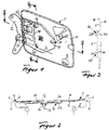
- a tank flap designated in its entirety by 1, is articulated on a vehicle body 4 by means of a bearing block 2 and a bearing arm 3 pivotably connected to it via hinge pin 33, in such a way that in its closed position it engages over a recess 5 formed in the vehicle body 4.
- the tank flap 1 in its closed position encloses a narrow gap 7 with the peripheral edge 6 of the trough 5.
- the fuel filler flap 1 is also acted upon by a spring 31, designed as a leaf spring, which is supported against the vehicle body 4 and engages on a longitudinal section of the hinge pin 33 which is designed as a crank arm 30.
- the fuel filler flap 1 itself consists of a smooth outer skin 8 and an insert 9, which is assigned to it and is formed by an embossed sheet metal part, via which it is in contact with the bearing arm 3.
- the outer skin 8 of the tank flap is connected to the insert part 9 by means of a flange 10.
- the insert 9 has in its central region a shape 11 directed towards the vehicle body 4, which is provided with a projection 12 in which a screw bolt 13 forming a fastening element for connecting the fuel filler flap to the bearing arm is fastened.
- the bolt 13 passes through a bore recess in the bearing arm and is screwed to it by means of a nut 14.
- a complementary recess in the bearing arm 3 is assigned to the projection 12.
- a total of three alignment marks 15, 16 and 17 are provided for the repeatable disconnection and attachment of the fuel filler flap in a position on the bearing arm that is correctly aligned with respect to a once-adjusted position.
- the alignment marks are on the corner points of an isosceles triangle, in the center of which the fastening device formed by a threaded bolt is arranged. are distributed.
- the arrangement is also such that two alignment marks 15, 16 in the base line 18 parallel to the pivot axis 33 of the bearing arm 3 and the third alignment mark 17 in the tip 19 pointing towards the free end of the fuel filler flap of the triangle are arranged.
- the alignment mark 15 arranged at the lower end of the base line 18 of the triangle forms the main centering of the tank flap on the bearing arm.
- the alignment mark 15 consists of a conical projection 20 formed on the insert 9 and a spherical receptacle 21 in the bearing arm 3.
- the alignment mark 16 arranged at the upper end of the base line 18 of the triangle and forming a first secondary centering consists of a prism 24 marked on the insert 9 and one Ball 25 provided in the bearing arm.
- the third alignment mark 17 arranged at the tip 19 of the triangle and forming a second secondary centering consists of a spherical segment 22 formed on the insert 9 and a calotte 23 formed in the bearing arm.
- the fuel filler flap is fixed to the alignment mark 15 which forms the main centering in all directions, ie in the "X-", Y- "'and” Z-direction, in such a way that it is connected to its determination on the alignment mark which forms the first secondary centering 16 has only one degree of freedom and in the sense of a pivoting movement eit about an axis lying in the base line 18 of the triangle. Thanks to the alignment mark forming the second secondary centering, the tank flap is then finally aligned in a precisely defined position.
Landscapes
- Engineering & Computer Science (AREA)
- Life Sciences & Earth Sciences (AREA)
- Sustainable Development (AREA)
- Sustainable Energy (AREA)
- Chemical & Material Sciences (AREA)
- Combustion & Propulsion (AREA)
- Transportation (AREA)
- Mechanical Engineering (AREA)
- Cooling, Air Intake And Gas Exhaust, And Fuel Tank Arrangements In Propulsion Units (AREA)
Claims (11)
- Trappe de réservoir (1) pour véhicule, qui recouvre dans sa position fermée une cavité (5) de la carrosserie du véhicule recevant un embout de remplissage de réservoir et qui est articulée de manière pivotante autour d'un axe placé au niveau d'un bord de la cavité de carrosserie, l'articulation de la trappe de réservoir comprenant un support (2) se fixant à la carrosserie du véhicule et un bras de soutien (3) se montant sur celui-ci de manière pivotante au moyen d'une cheville de charnière (33) et portant la trappe de réservoir, ainsi qu'un ressort de compression (31) appuyé contre la carrosserie et agissant sur le bras de soutien, et la trappe de réservoir étant fixée de manière amovible au bras de soutien,
caractérisée en ce que
en liaison avec une fixation amovible de la trappe de réservoir au bras de soutien (3) comprenant un élément de fixation relié en permanence à la trappe de réservoir, un dispositif composé d'au moins une marque d'alignement (15, 16, 17) placée sur la trappe de réservoir et coopérant avec une pièce complémentaire sur le bras de soutien est prévu pour fixer de manière reproductible en position correcte la trappe de réservoir sur le bras de soutien. - Trappe de réservoir selon la revendication 1, caractérisé en ce que la fixation amovible de la trappe de réservoir sur le bras de soutien comprend au moins un élément de fixation orienté perpendiculairement au plan de la trappe de réservoir et relié en permanence à la trappe de réservoir.
- Trappe de réservoir selon la revendication 1 et 2, caractérisée en ce que la fixation amovible de la trappe de réservoir sur le bras de soutien comprend une tige filetée (13) orientée perpendiculairement au plan de la trappe de réservoir et fixée de manière permanente à celle-ci, avec son écrou associé.
- Trappe de réservoir selon l'une des revendications 1 à 3, caractérisée en ce que le dispositif de fixation reproductible en position correcte de la trappe de réservoir sur le bras de soutien comprend au total trois marques d'alignement (15, 16, 17).
- Trappe de réservoir selon la revendication 4, caractérisée en ce que les marques d'alignement au nombre de trois au total sont placées dans les angles d'un triangle, en particulier d'un triangle équilatéral.
- Trappe de réservoir selon l'une des revendications 1 à 5, caractérisée en ce que deux marques d'alignement mutuellement opposées (15, 16) sont placées sur une ligne de base (18) du triangle équilatéral orientée parallèlement à l'axe de pivotement du bras de soutien.
- Trappe de réservoir selon l'une des revendications 1 à 6, caractérisée en ce que les marques d'alignement se composent à chaque fois d'une saillie et d'un évidement placés en alternance sur la trappe de réservoir et sur le bras de soutien, et présentent une courbure spatiale formant un accouplement à palier pivotant.
- Trappe de réservoir selon l'une des revendications 1 à 7, caractérisée en ce qu'au moins l'une des marques d'alignement se compose à chaque fois d'un logement en forme de calotte et d'une saillie en forme de segment sphérique.
- Trappe de réservoir selon l'une des revendications 1 à 8, caractérisée en ce qu'au moins l'une des marques d'alignement se compose d'une saillie conique et d'un logement de forme complémentaire.
- Trappe de réservoir selon l'une des revendications 1 à 9, caractérisée en ce qu'au moins l'une des marques d'alignement se compose de deux surfaces formées en alternance sur la trappe de réservoir et le bras de soutien et orientées de manière mutuellement complémentaire.
- Trappe de réservoir selon l'une des revendications 1 à 10, caractérisée en ce qu'au total trois marques d'alignement sont réparties dans les angles d'un triangle équilatéral et le dispositif de fixation formé d'une tige filetée (13) est placé au centre de ce triangle, de telle manière que deux des marques d'alignement (15, 16) soient placées sur la ligne de base (18) parallèle à l'axe de pivotement du bras de soutien et la troisième marque d'alignement soit placée sur le sommet du triangle pointé dans la direction de l'extrémité libre de la trappe de réservoir, dans laquelle une marque d'alignement placée à l'extrémité inférieure de la ligne de base du triangle et formant le centrage principal se compose d'une saillie conique et d'un logement sphérique et une marque d'alignement placée à l'extrémité supérieure de la ligne de base du triangle et formant un premier centrage secondaire se compose d'un prisme et d'une boule, et une troisième marque d'alignement placée au sommet du triangle et formant un deuxième centrage secondaire se compose d'un segment sphérique et d'une calotte.
Applications Claiming Priority (2)
| Application Number | Priority Date | Filing Date | Title |
|---|---|---|---|
| DE19739669A DE19739669A1 (de) | 1997-09-10 | 1997-09-10 | Tankklappe für Kraftfahrzeuge |
| DE19739669 | 1997-09-10 |
Publications (2)
| Publication Number | Publication Date |
|---|---|
| EP0901927A1 EP0901927A1 (fr) | 1999-03-17 |
| EP0901927B1 true EP0901927B1 (fr) | 2000-09-20 |
Family
ID=7841829
Family Applications (1)
| Application Number | Title | Priority Date | Filing Date |
|---|---|---|---|
| EP98113978A Expired - Lifetime EP0901927B1 (fr) | 1997-09-10 | 1998-07-27 | Trappe d'obturation pour couvrir la tubulure de remplissage pour véhicules automobiles |
Country Status (3)
| Country | Link |
|---|---|
| EP (1) | EP0901927B1 (fr) |
| DE (2) | DE19739669A1 (fr) |
| ES (1) | ES2151756T3 (fr) |
Families Citing this family (5)
| Publication number | Priority date | Publication date | Assignee | Title |
|---|---|---|---|---|
| DE19957967B4 (de) * | 1999-12-02 | 2009-06-04 | Bayerische Motoren Werke Aktiengesellschaft | Tankklappe aus Kunststoff für ein Kraftfahrzeug |
| DE10027570A1 (de) * | 2000-06-02 | 2001-12-06 | Bayerische Motoren Werke Ag | Scharnier |
| FR2889116B1 (fr) * | 2005-07-29 | 2007-12-14 | Mecaplast Sa | Trappe d'obturation de reservoir a carburant |
| DE102012010335A1 (de) | 2012-05-25 | 2013-11-28 | Gm Global Technology Operations, Llc | Vorrichtung zum Befestigen einer Tankklappe an einerFahrzeugkarosserie während eines Lackiervorganges |
| CN114506210A (zh) * | 2020-11-17 | 2022-05-17 | 宝适汽车部件(太仓)有限公司 | 用于机动车的油箱盖组件 |
Family Cites Families (1)
| Publication number | Priority date | Publication date | Assignee | Title |
|---|---|---|---|---|
| US5165749A (en) * | 1991-07-22 | 1992-11-24 | Molmec, Inc. | Gas cap cover adjustment device |
-
1997
- 1997-09-10 DE DE19739669A patent/DE19739669A1/de not_active Withdrawn
-
1998
- 1998-07-27 DE DE59800272T patent/DE59800272D1/de not_active Expired - Lifetime
- 1998-07-27 EP EP98113978A patent/EP0901927B1/fr not_active Expired - Lifetime
- 1998-07-27 ES ES98113978T patent/ES2151756T3/es not_active Expired - Lifetime
Also Published As
| Publication number | Publication date |
|---|---|
| DE19739669A1 (de) | 1999-03-11 |
| DE59800272D1 (de) | 2000-10-26 |
| EP0901927A1 (fr) | 1999-03-17 |
| ES2151756T3 (es) | 2001-01-01 |
Similar Documents
| Publication | Publication Date | Title |
|---|---|---|
| DE60005160T2 (de) | Automatisches rollenfalzwerkzeug | |
| EP0075259B1 (fr) | Dispositif pour l'orientation d'un élément articulé à un véhicule automobile | |
| DE69014873T2 (de) | Autoscharnier. | |
| EP0737454B1 (fr) | Endoprothèse, en particulier pour l'articulation sterno-claviculaire | |
| DE8914784U1 (de) | Scharnier mit verstellbarer Gelenkachse | |
| EP0901927B1 (fr) | Trappe d'obturation pour couvrir la tubulure de remplissage pour véhicules automobiles | |
| DE102005040826A1 (de) | Doppelgelenk-Scharnier zum Anbringen eines schwenkbaren Türflügels an einem Eckpfosten eines Fahrzeug-Laderaums oder Containers | |
| DE2420406A1 (de) | Schwenkeinrichtung | |
| EP1946686A2 (fr) | Cloison de séparation, en particulier cloison de douche | |
| EP0877677B1 (fr) | Dispositif servant au verrouillage d'un conteneur sur un chassis de vehicule | |
| DE8533057U1 (de) | Fahrzeugaußenspiegel | |
| DE3100138A1 (de) | Scharnierbefestigung fuer fluegelscharniere | |
| DE4209333A1 (de) | Mehrgelenkbeschlag für Fahrzeugtüren- oder Klappen | |
| EP1568540B1 (fr) | Dispositif d'amarrage de Bagages dans un véhicule | |
| EP0230259A2 (fr) | Boîtier en forme de parallélépipède pour objets | |
| DE10026667A1 (de) | Scharniervorrichtung | |
| DE4306802C1 (de) | Deckenstativ | |
| DE69716788T2 (de) | Wagenheber | |
| DE69700815T2 (de) | Antennenhaltevorrichtung zur Befestigung einer Stabantenne an einem Fahrzeug | |
| DE9214231U1 (de) | Mehrgelenkscharnier für Türen, Hauben, Klappen, Deckel oder Faltdachgestänge an Kraftfahrzeugen | |
| DE29716261U1 (de) | Tankklappe für Kraftfahrzeuge | |
| EP0486956B1 (fr) | Boîtier pour composants électriques ou électroniques | |
| DE4314858A1 (de) | Scharnier für Türen, Deckel oder dergleichen, insbesondere an Fahrzeugen | |
| DE2426489A1 (de) | Rueckblickspiegel fuer kraftfahrzeuge o.dgl. | |
| DE60005377T2 (de) | Dosiervorrichtung für schüttgut |
Legal Events
| Date | Code | Title | Description |
|---|---|---|---|
| PUAI | Public reference made under article 153(3) epc to a published international application that has entered the european phase |
Free format text: ORIGINAL CODE: 0009012 |
|
| 17P | Request for examination filed |
Effective date: 19980727 |
|
| AK | Designated contracting states |
Kind code of ref document: A1 Designated state(s): DE ES FR GB SE |
|
| AX | Request for extension of the european patent |
Free format text: AL;LT;LV;MK;RO;SI |
|
| GRAG | Despatch of communication of intention to grant |
Free format text: ORIGINAL CODE: EPIDOS AGRA |
|
| 17Q | First examination report despatched |
Effective date: 19991014 |
|
| AKX | Designation fees paid |
Free format text: DE ES FR GB SE |
|
| GRAG | Despatch of communication of intention to grant |
Free format text: ORIGINAL CODE: EPIDOS AGRA |
|
| GRAH | Despatch of communication of intention to grant a patent |
Free format text: ORIGINAL CODE: EPIDOS IGRA |
|
| GRAH | Despatch of communication of intention to grant a patent |
Free format text: ORIGINAL CODE: EPIDOS IGRA |
|
| GRAA | (expected) grant |
Free format text: ORIGINAL CODE: 0009210 |
|
| AK | Designated contracting states |
Kind code of ref document: B1 Designated state(s): DE ES FR GB SE |
|
| GBT | Gb: translation of ep patent filed (gb section 77(6)(a)/1977) |
Effective date: 20000921 |
|
| REF | Corresponds to: |
Ref document number: 59800272 Country of ref document: DE Date of ref document: 20001026 |
|
| ET | Fr: translation filed | ||
| REG | Reference to a national code |
Ref country code: ES Ref legal event code: FG2A Ref document number: 2151756 Country of ref document: ES Kind code of ref document: T3 |
|
| PGFP | Annual fee paid to national office [announced via postgrant information from national office to epo] |
Ref country code: SE Payment date: 20010702 Year of fee payment: 4 |
|
| PGFP | Annual fee paid to national office [announced via postgrant information from national office to epo] |
Ref country code: FR Payment date: 20010709 Year of fee payment: 4 |
|
| PGFP | Annual fee paid to national office [announced via postgrant information from national office to epo] |
Ref country code: ES Payment date: 20010716 Year of fee payment: 4 |
|
| PLBE | No opposition filed within time limit |
Free format text: ORIGINAL CODE: 0009261 |
|
| STAA | Information on the status of an ep patent application or granted ep patent |
Free format text: STATUS: NO OPPOSITION FILED WITHIN TIME LIMIT |
|
| 26N | No opposition filed | ||
| REG | Reference to a national code |
Ref country code: GB Ref legal event code: IF02 |
|
| PG25 | Lapsed in a contracting state [announced via postgrant information from national office to epo] |
Ref country code: GB Free format text: LAPSE BECAUSE OF NON-PAYMENT OF DUE FEES Effective date: 20020727 |
|
| PG25 | Lapsed in a contracting state [announced via postgrant information from national office to epo] |
Ref country code: SE Free format text: LAPSE BECAUSE OF NON-PAYMENT OF DUE FEES Effective date: 20020728 Ref country code: ES Free format text: LAPSE BECAUSE OF NON-PAYMENT OF DUE FEES Effective date: 20020728 |
|
| EUG | Se: european patent has lapsed | ||
| GBPC | Gb: european patent ceased through non-payment of renewal fee |
Effective date: 20020727 |
|
| PG25 | Lapsed in a contracting state [announced via postgrant information from national office to epo] |
Ref country code: FR Free format text: LAPSE BECAUSE OF NON-PAYMENT OF DUE FEES Effective date: 20030331 |
|
| REG | Reference to a national code |
Ref country code: FR Ref legal event code: ST |
|
| REG | Reference to a national code |
Ref country code: ES Ref legal event code: FD2A Effective date: 20030811 |
|
| REG | Reference to a national code |
Ref country code: DE Ref legal event code: R082 Ref document number: 59800272 Country of ref document: DE Representative=s name: BONNEKAMP & SPARING, DE Effective date: 20110812 Ref country code: DE Ref legal event code: R081 Ref document number: 59800272 Country of ref document: DE Owner name: EDSCHA ENGINEERING GMBH, DE Free format text: FORMER OWNER: ED. SCHARWAECHTER GMBH, 42855 REMSCHEID, DE Effective date: 20110812 |
|
| PGFP | Annual fee paid to national office [announced via postgrant information from national office to epo] |
Ref country code: DE Payment date: 20110722 Year of fee payment: 14 |
|
| PG25 | Lapsed in a contracting state [announced via postgrant information from national office to epo] |
Ref country code: DE Free format text: LAPSE BECAUSE OF NON-PAYMENT OF DUE FEES Effective date: 20130201 |
|
| REG | Reference to a national code |
Ref country code: DE Ref legal event code: R119 Ref document number: 59800272 Country of ref document: DE Effective date: 20130201 |