EP0901550B1 - Tragbarer nadelvibrator - Google Patents
Tragbarer nadelvibrator Download PDFInfo
- Publication number
- EP0901550B1 EP0901550B1 EP97927239A EP97927239A EP0901550B1 EP 0901550 B1 EP0901550 B1 EP 0901550B1 EP 97927239 A EP97927239 A EP 97927239A EP 97927239 A EP97927239 A EP 97927239A EP 0901550 B1 EP0901550 B1 EP 0901550B1
- Authority
- EP
- European Patent Office
- Prior art keywords
- tube
- sleeve
- further characterized
- coupling
- shaft
- Prior art date
- Legal status (The legal status is an assumption and is not a legal conclusion. Google has not performed a legal analysis and makes no representation as to the accuracy of the status listed.)
- Expired - Lifetime
Links
Images


Classifications
-
- E—FIXED CONSTRUCTIONS
- E04—BUILDING
- E04G—SCAFFOLDING; FORMS; SHUTTERING; BUILDING IMPLEMENTS OR AIDS, OR THEIR USE; HANDLING BUILDING MATERIALS ON THE SITE; REPAIRING, BREAKING-UP OR OTHER WORK ON EXISTING BUILDINGS
- E04G21/00—Preparing, conveying, or working-up building materials or building elements in situ; Other devices or measures for constructional work
- E04G21/02—Conveying or working-up concrete or similar masses able to be heaped or cast
- E04G21/06—Solidifying concrete, e.g. by application of vacuum before hardening
- E04G21/08—Internal vibrators, e.g. needle vibrators
Definitions
- the invention relates to a vibrator with portable needle, i.e. a device for production of vibrations with a view to compacting materials, in particular concrete, of the so-called internal vibrator type or vibrating needle, comprising a needle formed by a tube, suitable for being immersed inside a mass of materials to compact and emit vibrations therein mechanical propagating in directions at least substantially radial to the longitudinal axis of the needle.
- a vibrator with portable needle i.e. a device for production of vibrations with a view to compacting materials, in particular concrete, of the so-called internal vibrator type or vibrating needle, comprising a needle formed by a tube, suitable for being immersed inside a mass of materials to compact and emit vibrations therein mechanical propagating in directions at least substantially radial to the longitudinal axis of the needle.
- Needle vibrators are known from and have been used on construction sites, by professionals, to vibrate concrete. These devices include a vibrating needle incorporating a motor pneumatic (turbine) or electric connected to a air compressor or electrical source by an air or electricity supply cable.
- a motor pneumatic (turbine) or electric connected to a air compressor or electrical source by an air or electricity supply cable.
- the electric motor is separated from the needle, is placed on the ground and connected by a long flexible transmission to the needle which is then pendulum type.
- the motor must drive the needle at speeds greater than 10,000 rpm.
- US-2,232,842 describes a needle apparatus for producing vibrations for the compaction of concrete comprising: a rigid tube closed at one of its ends with an elongated eccentric body guided by rotation in the tube thanks to two bearings fixed on supports at each end of the tube; a flexible shaft connecting the body eccentrically to the output shaft of a motor provided with operating handles; a portion semi-rigid tubular attached by end fittings to the rigid tube and to the motor, and comprising an internal element consisting of a metal wire wound in a helicoid which serves as support for the flexible shaft, an inextensible flexible blocking tube not foldable formed of a metal band wound in a helicoid covering the metal wire helically wound, a tubular lacing of helically braided metal wires, immediately stretched in contact around the blocking tube while being hooked to rigid pipe and motor end fittings, a strip of rubberized fabric or coated with a rubber-like cement wound in a helix on the lacing for the keep in contact with the blocking tube, successive
- the semi-rigid tubular portion has a diameter external identical to that of the rigid tube.
- the rubber top layer is vulcanized under the collars or flanges of the end fittings to the tube and to the motor.
- the flexible shaft is coupled to the output shaft of the motor by a coupling to the level of the end fitting.
- the set is extremely complex, requires a large number of parts, and is expensive to manufacture and assemble.
- DE-U-29 515 762 describes a vibrator adaptable to the chuck of an electric drill comprising a tube containing an eccentric body, a shaft flexible connected to the eccentric body and to the mandrel of the drill, a flexible rubber hose extending between a tube fitting and a fitting at the end of the shaft inserted into the mandrel.
- Each fitting includes a shaft guide bearing.
- This device is free sheath protecting the tree, allowing movement relative to the shaft inside the pipe, leading to wear of the rubber hose, and vibrations, and beat.
- the mandrel of the drill is not protected from splashing water or concrete, which also leads to rapid wear of the drill (including its bearing).
- the set requires many machining operations, a large number of parts, and is expensive to manufacture and complex to assemble.
- the invention therefore aims to provide a needle type apparatus for the production of vibrations for the compaction of materials, in concrete, which provides a solution to this problem and can in practice satisfy the market for particular craftsmen or DIYers.
- crimping we means any process of rotational coupling and axial connection of a female part and a male part by relative plastic and / or elastic deformation of at least one of the two rooms. This term therefore includes not only the crimping proper with or without bonding, but also hoop connections (deformations elastic).
- the mechanical characteristics of the tubular sleeve and the sheath formed by the two helical strands are adapted in depending on the intended use of the device, so the needle (closed tube and eccentric rotating body elongated shape) can be introduced into the mass of material by the own weight of the needle possibly supplemented by a slight vertical push from top to bottom exercised by a user manually on the means of handling, while allowing relative movements in bending in the case where a higher resistance is encountered during the introduction, and ensuring elasticity in bending bringing back and now at rest the needle in the axial extension of the sleeve and the output pin.
- the sleeve is possibly synthetic material composite and / or reinforced and / or non-stick exterior surface.
- the tube and the sleeve have the same outer diameter, and this diameter is advantageously between 20 mm and 50 mm, more particularly between 25 mm and 35 mm.
- the tube diameter is determined based on dimensions radials of the eccentric body forming an imbalance, and bearings that support it.
- the length of the tube is determined for the device to be usable in the majority of situations encountered.
- this length is between 200 mm and 400 mm, more particularly between 250 mm and 350 mm.
- the length of the tubular sleeve is adapted to allow work at height, the user having the device in hands, carrying it and holding it by the means of handling associated with the drive motor.
- the sleeve length is between 1 and 10 times the length of the tube.
- the sleeve length is between 250 mm and 2000 mm, especially of the order of 500 mm.
- said means for connecting the tube and the sleeve are means for fitting and crimping a male end piece in a female end cap.
- said connection means comprise a connecting piece interposed between the sleeve and the tube.
- connection means define a cylindrical groove of receiving and crimping the end of the sleeve and the end of the flexible sheath, and this groove cylindrical includes projecting ribs inward from an outer wall of the throat cylindrical to enter the sleeve.
- the removable coupling means can be made in the form of a screw / nut system accessible by access light, or from a coupling to axial splines and / or radial plug.
- the rigid head comprises a casing, and a fixing part of the end of the sleeve and the sheath relative to the casing.
- the piece of attachment is rigidly associated with the head housing rigid, and defines a cylindrical receiving housing and for crimping the end of the sleeve and the end flexible sheath, this cylindrical housing comprising ribs projecting inwardly at from an external wall of the cylindrical housing for penetrate the thickness of the sleeve.
- the tube is closed by a rounded cap, mounted irremovable at the end of the tube.
- the tube is in additionally rigid, preferably made of metallic material.
- the eccentric body is coupled to the end of the shaft by crimping.
- each bearing is a bearing
- the eccentric body includes two pins carried by the inner cages of the two bearings, and one of the pins is directly coupled to the end of the shaft - in particular by crimping -.
- the inner cages bearings are attached to the pins, and the cages outer bearings are inserted into the tube with radial clearance.
- the eccentric body includes a central cylindrical guided core by the bearings, and a portion of cylinder -in particular a half-cylinder- fixed attached to the core to form unbalance around the axis of rotation of the core defined by the bearings.
- Such an eccentric body is extremely simple and inexpensive to manufacture.
- the flexible sheath comes into contact with the internal wall cylindrical of the sleeve and the shaft is mounted in the sheath flexible with radial clearance.
- the electric motor is suitable for driving the spindle output and the body offset at a speed of rotation less than 5000 rpm, especially between 2500 and 3500 rpm.
- the device can be the object of several embodiments.
- it is coupled to a portable drill traditional electric motor.
- said means of junction are of the removable type preferably with assembly and quick disassembly.
- the drill includes, in a traditional way, handling means which act as means of handling of the device according to the invention.
- the device is completely autonomous and incorporates an electric drive motor.
- the device is characterized in that it comprises: i) an electric drive motor comprising an output pin coupled to the end of the flexible shaft by a coupling part, in particular crimping at the end of the shaft.
- This electric drive motor is housed in a casing which carries or which defines the means of handling the device (handle, engine control button ).
- the rigid head has a housing and an end attachment sleeve and flexible sheath relative to the housing.
- the combination of features of the invention makes it possible to end up with a very portable device light, allowing work at height, including the needle and the tubular sleeve (incorporating the shaft and the sheath flexible) are small in diameter, highly efficient vibratory, able to be easily introduced through or behind reinforcements or obstacles or in recesses, and low cost.
- a rotating body eccentric of elongated shape mounted between two bearings as source of vibration allows coupling of the needle vibrating with a drive motor associated with means of handling of the device, via a transmission (shaft, sheath with two helical strands and flexible tubular sleeve), whose flexibility and the elasticity in bending are a compromise allowing also well the passage around obstacles and the introduction of the needle, while avoiding that the needle and / or the flexible transmission is not subject to parasitic movements (beating, swaying ).
- this embodiment of the needle allows, thanks to its small diameter (in particular between 20 and 50 mm), use a tubular sleeve of the same diameter and appropriate flexibility.
- the vibrations produced are homogeneous amplitude over the entire height of the needle, high efficiency (no energy losses in non-radial directions), and are not retransmitted to means of handling the device.
- the user can therefore carry, handle and guide the needle while holding the device by the motor housing, in a simple and comfortable way. Also, when the needle is extracted, there is no concrete rise and the space left by the exit of the needle, of small diameter, fills up as measurement of extraction.
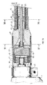
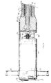
- the apparatus shown in Figure 1 is of the type intended to be fixed on an electric drill traditional portable, which is therefore not part integral of the apparatus according to the invention in this mode of production.
- the drill 1 comprises, so traditional, a handle 2 of operation, a button 3 of control of an alternating electric motor (single phase 220 V rotating at a speed conventionally between 1500 rpm and 4000 rpm) drive in rotation of an output pin 4.
- the chuck of the drill is disassembled for mounting the device according to the invention.
- the apparatus comprises a vibrating needle 5 formed by a tube 6 closed at one 7 of its ends by a rounded metal plug 8 mounted irremovable, for example force-fitted and / or glued and / or punched at the end of the tube 6.
- the vibrating needle 5 also comprises an eccentric body 9, of elongated shape, rotatably mounted in the tube 6, thanks to two bearings 10, 11 each formed of a bearing, and housed inside the tube 6, one near its closed end 7, the other near its other end 12, so that guide the eccentric body 9 in rotation.
- the needle 5 thus formed is associated to an engine block (drill 1) via a flexible tubular assembly 14.
- This tubular assembly 14 basically has two functions: first, it allows mounting of needle 5 relative to the block motor 1, so that the needle 5 is carried by this engine block 1. Thus, when handling the means 2, 3 of handling the drill 1, carry and guide the needle 5.
- the tubular assembly 14 also has the function to transmit the rotary movement of the output spindle 4 to the body 9 eccentric to drive it in rotation.
- the tubular assembly 14 includes a sleeve tubular 15 extending the tube 6, of diameter outside the less substantially identical to that of tube 6.
- the outer surface 16 of the tubular sleeve 15 extends to the less substantially in continuity and as an extension of the outer surface 17 of the tube 6.
- the tubular sleeve 15 is hollow cylindrical and delimited in a sealed manner with the engine block 1 and tube 6, a cylindrical internal space closed.
- the sleeve 15 is dimensioned and constituted of an appropriately chosen material so that it has axial compressive strength and shape adapted to allow the introduction of tube 6 to within the mass of the material to be compacted, but a adequate flexibility sufficient to allow bending in the case where a resistance, greater than the resistance opposed by the single material, is encountered during the introduction, in particular in the event of a stop against a workpiece reinforcement or an obstacle, as shown in figure 1.
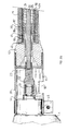
- the sleeve 15 has a form at rest which is straight, that is to say straight.
- tubular assembly 14 is dimensioned and made up of a material chosen so that when the device is held by the user, this tubular assembly 14 can be kept in a straight shape when needle 5 is normally introduced inside the mass of material without encountering an obstacle, as shown figure 2.
- the sleeve 15 is consisting of an axially incompressible hollow tube but flexible, synthetic material.
- This synthetic material can be composite or not, reinforced or not, plastic or elastic. The mechanical characteristics of this material and hollow tube are chosen to obtain resistance in axial compression and flexibility of the assembly tubular 14 as mentioned above.
- the outer surface 16 of the sleeve 15 is advantageously covered or made up of a non-stick material such as TEFLON (registered trademark) in order to avoid sticking to the mass of material to extraction.
- TEFLON registered trademark
- the tubular assembly 14 includes a flexible transmission incorporated inside the sleeve tubular 15.
- This transmission includes a sheath flexible 21 contained in the sleeve 15, and a shaft flexible transmission 22 contained in the flexible sheath 21 and coupled to the eccentric body 9 to be able to drive it in rotation.
- Mechanical characteristics and dimensions of the flexible transmission are adapted to allow transmission of the torque from the motor driving the engine block (drill 1) to the body 9 eccentric, allowing bending deformations of the tubular assembly 14.
- the flexible shaft 22 is for example a flexible metal shaft whose length is of the order of, or slightly higher than that of the sheath 21, so that have two ends 23, 24, one of which 23 is coupled to the output pin 4 of the drive motor, and the other 24 of which is coupled to the eccentric body 9.
- the flexible shaft 22 is for example formed at least one metallic filament wound in turns helical contiguous or not, or even two filaments coaxial and concentric wound in opposite directions, extending one inside the other and joined to their ends.
- the sheath 21 is adapted to allow a free rotation of the shaft 22 around its axis.
- a radial clearance 25 is formed between the shaft 22 and the sheath 21.
- the flexible sheath 21 is a sheath metallic comprising at least two strands 70, 71 metal helical coils in opposite directions (i.e. opposite steps, one on the left, the other on the right), extending one (70) inside the other (7).
- the flexible sheath 21 advantageously comprises a outer tubular covering 72 surrounding the strand helical exterior 71.
- This coating 72 is provided by example in the form of a metallic braid and / or a synthetic film conforming to the outer helical strand 71.
- Such a sheath 21 makes it possible to limit the games in torsion in both directions, is flexible, and elastic in bending.
- Each helical strand 70, 71 is a strand formed of a winding of an elastic metallic filament, for example in hard steel, in regular disjointed turns.
- the cross section of the filament forming the strands 70, 71 is flattened. She is in shape substantially oval or rectangular.
- the two strands 70, 71 can be formed from the same metallic filament or no.
- the turns of the helical strand 70 interior come into contact with the turns of the helical strand 71 exterior which are themselves coated with the coating exterior 72.
- a radial space 25 is formed over the entire length of the sheath 21 between the shaft 22 and the sheath 21, that is to say between the external surface of the shaft 22 and the helical strand 70 inside.
- This space radial 25 between the shaft 22 and the sheath 21 avoids premature wear of the shaft 22, especially when the tubular assembly 14 is bent.
- the flexible sheath 21 comes in contact with the cylindrical internal wall of the sleeve 15.
- the tubular sleeve 15 is connected to the tube 6 by means 26, 27 of connection adapted from a part to secure the ends 18, 12 of these tubes 6 and sleeve 15 ensuring sealing and continuity of their external surface 16, 17 and, on the other hand to realize maintaining the corresponding end 29 of the sheath 21 relative to the tube 6 and to the sleeve 15.
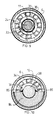
- the means 26, 27 for connecting the tube 6 and the sleeve 15 are interlocking means and crimping a male end 26 into a female end 27.
- the male end piece 26 is formed by a metal socket defining a cylindrical groove 73 for receiving and crimping of the end 18 of the sleeve 15 and of the end 29 of the flexible sheath 21.
- the sleeve metallic 26 covers these ends 18, 29 which it receives between two cylindrical walls 74, 75 defining between them the groove 73.
- These walls 74, 75 are connected between them by a connecting wall 76 in the form of crown and cross section (by a radial plane) curve so that the outer wall 75 approaches the internal wall 74 by reduction of the curvature of the wall link 76 during crimping. So, we squeeze together radially the ends 18, 29 in the groove 73.
- the outer wall 75 includes ribs 77 extending in inward projection (toward the inner wall 74) for penetrate the thickness of the sleeve 15 whose end 18 is crushed by crimping.
- the sleeve 26 is placed at the ends 18, 29 sleeve 15 and sheath 21, then the assembly is inserted into the end of the tube 6 forming a female end piece 27, on which a radial pressure is exerted towards the interior using a crimping tool to join together.
- connection means also include a metal socket 78 similar to that of the variant of FIG. 5a, and defining the cylindrical groove 73 of receiving and crimping the ends 18, 29 with a outer wall 80 provided with crimping ribs 82, a internal wall 79 and a connecting ring 81.
- the socket 78 constitutes a piece of fitting interposed between the sleeve 15 and the tube 6.
- the crown 81 is indeed fitted with a thread suitable for be screwed into a thread 83 at the end of the tube 6.
- the crimping pressure is exerted directly on the external wall 80 of the socket 78.
- the sleeve 15 and / or the sheath 21 and / or the socket 26, 78 and / or tube 6 can also be glued to each other during assembly.
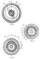
- Each of the bearings 10, 11 carrying and guiding the eccentric body 9 in the tube 6 is a bearing ball.
- the eccentric body 9 extends between two pins 32, 33 carried by the inner cages 36, 37 of the two bearings 10, 11.
- the two bearings 10, 11 are placed in tube 6 with their axes of rotation aligned one with the other and with the main axis of symmetry of the tube 6.
- the body 9 eccentric includes a central cylindrical core 38 guided by the two pins 32, 33.
- the central core 38 and the two pins 32, 33 are formed by a cylindrical bar which extends over the entire length of the tube 6 between the two bearings 10, 11.
- a portion 84 of a section of tube cylindrical is attached and fixed on the core 38 to form unbalance around the axis of rotation of the core 38 defined by the bearings 10, 11.
- This portion 84 is not symmetrical of revolution and is preferably half (cut by an axial diametral plane) of cylindrical tube section, as shown in figure 10, whose internal diameter corresponds to the external diameter of the core 38.
- This portion 84 formed of a heavy metal, for example steel, is simply welded to the core 38 by weld beads 85 ( Figure 10) and / or fixed by any other means (screws, glue ...) on the core 38.
- the body 9 thus formed has a section transverse line which is generally in the form of sector angular between 90 ° and 180 °, preferably equal to 180 °. In this way, the center of gravity of the body 9 is distant from the main axis of symmetry of tube 6 and therefore the axis of rotation of the pins 32, 33.
- the flexible shaft 22 is directly coupled to the eccentric body 9.
- the pin 33 has a bore receiving the end 24 of the shaft 22. The assembly is secured in rotation by example by crimping the pin 33 on the end 24 (the pin 33 being crushed using pliers against the end 24) and / or bonding. This assembly of the trunnion 33 to the tree 22 not only makes it possible to secure in rotation of the shaft 22 and the pin 33, but also of keep them in their relative axial position one by compared to each other.
- the inner cages 36, 37 of bearings 10, 11 are fixed on the pins 32, 33, and the outer cages 34, 35 of the bearings 10, 11 are inserted into the tube 6 with, at least during assembly, a sufficient radial clearance to allow axial movement relative of the bearings 10, 11 in the tube 6 during the mounting.
- the outer cages 34, 35 of the bearings can be integral with tube 6 in the event that using force mounting and / or bonding of cages 34, 95 to tube 6.
- a radial clearance between the cages 34, 35 and the tube 6 can be kept after mounting in operation.
- a radial clearance not only is not harmful in functioning, but on the contrary can be beneficial point of view of vibrational efficiency.
- the bearings 10, 11 in the tube 6 have important dimensions and are chosen to resist with a sufficient service life at high vibrations generated by the body 9.
- the rigid head 19 For mounting the tubular sleeve 15 on the drill 1, the rigid head 19 comprises a casing 39 external, a fixing piece 40 assembled to the casing 39 of removable and receiving the end 20 of the sleeve 15 and the end 41 of the sheath 21.
- the part fixing 40 comprises a cylindrical housing 42 of receiving and crimping the end 20 of the sleeve 15 and from the end 41 of the sheath 21, this housing cylindrical 42 comprising ribs 86 extending in protruding inwards from an external wall 87 of the cylindrical housing 42 to penetrate the thickness of the sleeve 15.
- the fixing piece 40 further comprises a internal cylindrical wall 88 extending opposite the external cylindrical wall 87 to define between them the cylindrical housing 42.
- the end 20 of the sleeve 15 and that 41 of the sheath 21 in the cylindrical housing 42 is crimped the whole by crushing radially inwards the outer wall 87 using a crimping tool.
- the end 41 of the sheath 21 and / or the end 20 of the sleeve 15 is advantageously glued to the interior of the cylindrical housing 42, so as to form a tight assembly.
- the fixing piece 40 is assembled to the casing 39 by any removable assembly means (thread of part 40 and tapping of casing 39; one or more radial locking screw; bayonet mount ).
- the housing 39 of the rigid head 19 is tightened on the collar 44 of the drill 1 using a collar 45 or by any other means of assembly fast.
- the end 23 of the shaft 22 is coupled to pin 4 of the drill outlet 1 by by means of junction means 46, 47 comprising a coupling piece 46 mounted for rotation by crimping at the end 23 of the shaft 22, and a part 47 adaptation arranged so as to connect and couple the coupling piece 46 to pin 4 of the output drill 1.
- the coupling piece 46 is assembled and coupled in rotation to the end 23 of the shaft 22 by crimping and if necessary, by gluing. This assembly has also for the function of maintaining the axial positions relative of the coupling piece 46 with respect to the end 23 of the shaft 22.
- the coupling piece 46 comprises a bore receiving the end 23 of the shaft 22. This bore is crimped on the end 23 by tightening with using pliers or the like, and possibly glued.
- the coupling piece 46 defines a receiving housing 89 of the adaptation piece 47, this reception housing 89 and adaptation piece 47 having conjugate forms adapted to prohibit any relative rotation and ensure rotation coupling of the adaptation part 47 relative to the part coupling 46.
- the coupling piece 46 is formed of a cylindrical flywheel extending radially in the majority of the radial space provided by the housing 39 in the head 19.
- the receiving housing 89 is formed by a parallelepipedal radial recess 89 centered on the axis and at the end of the part coupling 46, and the adapter piece 47 is rectangular to be able to fit into this recess 89.
- the flywheel formed by the part coupling 46 absorbs vibrations between the shaft 22 and the output pin 4 of the motor, the guide bearing is thus preserved.
- the adaptation piece 47 includes a internal thread 50 receiving the thread of the spindle 4.
- the part adapter 47 is chosen with its thread 50 in function of drill 1 to which the device must be associated, that is to say according to the diameter and the pitch of the output pin thread 4.
- the adapter piece 47 is thus detachably coupled to the coupling piece 46, and to the output pin 4 of the drill 1.
- said means of joint comprising a coupling part 53 mounted integral in rotation, by crimping, at the end 23 of the shaft 22, and coupled to the output pin 4 by removable means of rotation coupling; and at least an access light 90 formed through the casing 39 of the rigid head 19 opposite the output pin 4 for the mounting and coupling of the coupling piece 53 on the output pin 4.
- said means removable rotational coupling are formed of thread the output spindle 4 of the drill 1 and a thread blind 91 provided in the coupling part 53, the external surface is suitable (for example with hexagon) to allow it to be tightened using a tool (flat wrench example) inserted through the light 90 adapted to this effect.
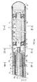
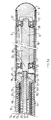
- the device is not of the type intended to be associated with a portable drill, but incorporates otherwise an electric drive motor 51 comprising an output pin 52 coupled to the end 23 of the shaft 22 by the coupling part 53.
- the motor 51 is single phase alternating type and rotates at a speed of rotation less than 5000 rpm, including between 2500 rpm and 3500 rpm.
- the coupling piece 53 is set, and optionally glued to the end 23 of the shaft 22.
- the coupling piece 53 is mounted integral in rotation of the spindle 52 by grooves parallel to the axis formed on the spindle 52 and on a bore 92 of the coupling piece 53, and by a radial split pin 93 accessible through the light 90.
- the rigid head 19 further comprises an outer casing 54 which, in the variant shown in Figure 11 is also the housing containing the motor 51.
- An access light 90 is provided through this casing 54 for assembly or disassembly joining means.
- the fixing piece 40 is preferably fixed in a non-removable manner on the casing 54 of the rigid head 19, for example by punching and / or riveting and / or gluing ...
- the casing 54 is generally cylindrical and contains and bears the motor 51.
- a casing 62 larger is planned from the rigid head 19 for enclose the motor 51.
- the casing 54 or 62 of the motor 51 also carries two handles 55 for handling the device, as well as a button 56 for controlling the engine operation 51.
- the tubular sleeve 15 has a length between 1 and 10 times the length of the tube 6.
- the length of the sleeve 15 is included between 250mm and 2000mm, and in particular of the order of 500mm, for a length of tube 6 of between 200 mm and 400 mm, in particular between 250 mm and 350 mm.
- the motor unit of the drill 1 and the means 2, 3 are located at overall working height at the level of the user's hands while standing.
- the invention may be the subject of other variant embodiments and the various embodiments and variants described above can be combined or swapped.
- the sleeve 15 has a length 30 cm and a diameter corresponding to that of tube 6, and the tube 6 has a length of 32 cm.
- the electric motor and the eccentric body 9 rotate at 2500 rpm for the F25 device and 3000 rpm for the F33 device.
- the density of concrete specimens vibrated is measured fresh and hardened (after release from the mold for one day and hold for 28 days at 20 ° C at 100% relative humidity. Compressive strength at the hardened state was also measured according to the AFNOR NF standard P18-406. Each test was carried out simultaneously on three test tubes.
- the devices according to the invention are as effective as the device professional of the prior art, mass differences volume being less than 1%, the resistance to compression even being slightly improved.
Landscapes
- Engineering & Computer Science (AREA)
- Architecture (AREA)
- Mechanical Engineering (AREA)
- Civil Engineering (AREA)
- Structural Engineering (AREA)
- Apparatuses For Generation Of Mechanical Vibrations (AREA)
- Flexible Shafts (AREA)
- On-Site Construction Work That Accompanies The Preparation And Application Of Concrete (AREA)
Claims (18)
- Gerät des Rüsseltyps zur Erzeugung von Vibrationen im Hinblick auf eine Materialmasse, insbesondere von Beton, das eine Kombination von den folgenden Teilen aufweist:a) ein an einem seiner Enden (7) geschlossenes Rohr (6),b) einen exzentrischen Körper (9) von länglicher Form, der drehbar in dem Rohr (6) angebracht ist,c) zwei im Inneren des Rohrs (6) eingebettete Lager (10, 11), von denen das eine in der Nähe von dessen geschlossenem Ende (7) und das andere in der Nähe von dessen anderem Ende angebracht ist, zur Führung des in Rotation befindlichen, exzentrischen Körpers (9),d) eine das Rohr (6) verlängernde, röhrenförmige Muffe (15) mit einem etwa mit dem Rohr (6) identischen Außendurchmesser, wobei diese Muffe (15) einen Widerstand gegen axiale Kompression und eine zur Einführung des Rohres (6) in das Innere der Materialmasse angepasste Form, aber eine geeignete Flexibilität aufweist, die für den Fall eines während der Einführung auftretenden Widerstandes eine Durchbiegung zulässt,e) einen in der Muffe (15) enthaltenen, flexiblen Mantel (21), der mindestens zwei im entgegengesetzten Sinn, koaxial schraubenförmig gewickelte Streifen umfasst, von denen einer im Inneren des anderen liegt wobei die beiden Streifen von einem äusseren Mantel umgeben sind,f) eine im Inneren des flexiblen Mantels (21) befindliche, mit dem flexiblen Körper (9) zur Ermöglichung des Rotationsantriebs verbundene, flexible Übertragungswelle (22),g) Mittel (26, 27, 28) zur Befestigung des Rohrs (6) mit der Muffe (15), die einerseits zur kraftschlüssigen Verbindung der Enden (12, 18) des Rohrs (6) und der Muffe (15), wobei eine Kontinuität ihrer äusseren Oberflächen (16, 17) in etwa gewährleistet ist, und andererseits zur Durchführung der Aufnahme des Endes (29) des Mantels (21) in das Rohr (6) und die Muffe (15) angepasst sind,h) einen starren Kopf (19) zur Befestigung der anderen Enden (20, 41) der Muffe (15) und des Mantels (21), wobei der Kopf mit Verbindungsmitteln (46, 47, 53) ausgestattet ist, um die Koppelung der Welle (22) mit der Ausgangsspindel (4, 52) eines Elektromotors zum Drehantrieb in Verbindung mit den Bedienungselementen (2, 3, 55, 56) des Gerätes zuzulassen.
- Gerät gemäß dem Anspruch 1, das außerdem dadurch gekennzeichnet ist, dass die Muffe (15) aus synthetischem Material ist.
- Gerät gemäß einem der Ansprüche 1 und 2, das außerdem dadurch gekennzeichnet ist, dass die Länge der Muffe (15) zwischen ein Mal und zehn Mal der Länge des Rohres (6) entspricht.
- Gerät gemäß Anspruch 3, das außerdem dadurch gekennzeichnet ist, dass die Länge der Muffe (15) zwischen 250 mm und 2000 mm liegt, insbesondere in der Größenordnung von 500 mm.
- Gerät gemäß einem der Ansprüche 1 bis 4, das außerdem dadurch gekennzeichnet ist, dass die Verbindungsmittel des Rohrs (6) und der Muffe (15) Mittel zum Einfügen und Einfassen einer männlichen (26) in einer weiblichen (27) Mündung sind.
- Gerät gemäß einem der Ansprüche 1 bis 5, das außerdem dadurch gekennzeichnet ist, dass die Verbindungsmittel ein Verbindungsstück (78) umfassen, das zwischen die Muffe (15) und das Rohr (6) gestellt ist.
- Gerät gemäß einem der Ansprüche 5 und 6, das außerdem dadurch gekennzeichnet ist, dass die Verbindungsmittel eine zylindrische Nute zur Aufnahme und zum Einfassen des Endes (18) der Muffe (15) und des Endes (29) der flexiblen Welle (22) bestimmen und dass diese zylindrische Nute Rippen umfasst, die sich von einer äußeren Wand der zylindrischen Nute ausgehend vorspringend ins Innere erstrecken, um in die Muffe (15) einzudringen.
- Gerät gemäß einem der Ansprüche 1 bis 7, das außerdem dadurch gekennzeichnet ist, dass die Verbindungsmittelein kraftschlüssig durch ein gedrehtes Einfassen des Endes (23) der Welle (22) montiertes Kupplungselement (46) ,ein Passstück (47), das zur Verbindung und Kuppelung des Kupplungsteils (46) an die Ausgangswelle (4) angeordnet ist, wobei dieses Passstück (47) an die Ausgangswelle (4) durch eine Verschraubung drehbar gekuppelt ist und das Kupplungsteil (46) ein Aufnahmelager (89) des Kupplungsteils (47) bestimmt, wobei dieses Aufnahmelager (89) und das Kupplungsteil (47) zugeordnete Formen aufweisen, die zur Verhinderung jeglicher relativer Rotation und zur Sicherung der drehbaren Kuppelung des Passstücks (47) in Bezug auf das Kupplungsteil (46) angepasst sind, umfassen.
- Gerät gemäß einem der Ansprüche 1 bis 7, das außerdem dadurch gekennzeichnet ist, dass die Verbindungsmittelein kraftschlüssig durch ein gedrehtes Einfassen des Endes (23) der Welle (22) montiertes Kupplungselement (53) und durch demontierbare Mittel zur drehbaren Verbindung an die Ausgangswelle (4) gekuppelt ist,mindestens eine durch den starren Kopf (19) im Hinblick auf die Ausgangswelle (4) zur Montage und Kuppelung des Kupplungsteils (53) auf die Ausgangswelle (4) ausgesparte Zugangsöffnung (90), umfassen.
- Gerät gemäß einem der Ansprüche 1 bis 9, das außerdem dadurch gekennzeichnet ist, dass der starre Kopf (19) ein Gehäuse (39, 54) und ein Teil (40) zur Befestigung des Endes (20) der Muffe (15) und (41) des Mantels (21) an das Gehäuse (32, 54) aufweist.
- Gerät gemäß dem Anspruch 10, das außerdem dadurch gekennzeichnet ist, dass das Teil zur Befestigung (40) starr mit dem starren Kopf (19) verbunden ist und ein zylindrisches Lager (42) zur Aufnahme und zum Einfassen des Endes (20) der Muffe (15) und des Endes (41) des flexiblen Mantels (21) bestimmt, wobei dieses zylindrische Lager (42) Rippen (86) umfasst, die sich von einer äußeren Wand (87) des zylindrischen Lagers (42) ausgehend vorspringend ins Innere erstrecken, um in die Dicke der Muffe (15) einzudringen.
- Gerät gemäß einem der Ansprüche 1 bis 11, das außerdem dadurch gekennzeichnet ist, dass das Rohr (6) durch einen rund geformten Pfropfen (8) verschlossen ist, der auf das Ende (17) des Rohrs (6) unabnehmbar gelagert ist.
- Gerät gemäß einem der Ansprüche 1 bis 12, das außerdem dadurch gekennzeichnet ist, dass der exzentrische Körper (9) mit dem Ende der Welle (22) durch Einfassung angekoppelt ist.
- Gerät gemäß einem der Ansprüche 1 bis 13, das außerdem dadurch gekennzeichnet ist, dass jedes Lager (10, 11) ein Wälzlager ist und dass der exzentrische Körper (9) zwei von den inneren Käfigen (36, 37) der beiden Wälzlager getragene Zapfen (32, 33) aufweist, und dass einer der Lagerzapfen (32, 33) direkt mit einem Ende (24) der Welle (22), insbesondere durch Einfassen, verbunden ist.
- Gerät gemäß Anspruch 14, das außerdem dadurch gekennzeichnet ist, dass:die inneren Käfige (36, 37) der Wälzlager (10, 11) auf den Lagerzapfen (32, 33) befestigt sind,die äusseren Käfige (34, 35) der Wälzlager (10, 11) mit einem radialen Spiel in das Rohr (6) eingelassen sind.
- Gerät gemäß einem der Ansprüche 1 bis 15, das außerdem dadurch gekennzeichnet ist, dass der exzentrische Körper (9) einen zentralen, zylindrischen, durch die Lager (10, 11) geführten Kern (38) aufweist, sowie einen, auf dem Kern (38) zur Hervorrufung einer Unwucht um die Rotationsachse (38) aufgesetzt befestigten, durch die Lager (10,11) begrenzten Abschnitt (84) des Zylinders, insbesondere ein Halbzylinder.
- Gerät gemäß einem der Ansprüche 1 bis 16, das außerdem dadurch gekennzeichnet ist, dass der flexible Mantel (21) mit der internen, zylindrischen Wand der Muffe (15) in Kontakt kommt und dass die Welle (22) in dem flexiblen Mantel (21) mit einem radialen Spiel angebracht ist.
- Gerät gemäß einem der Ansprüche 1 bis 17, das außerdem dadurch gekennzeichnet ist, dass der Elektromotor angepasst ist, um die Ausgangswelle (4) und den exzentrischen Körper (9) mit einer Drehgeschwindigkeit unter 5000 U/min, insbesondere zwischen 2500 und 3500 U/min anzutreiben.
Applications Claiming Priority (3)
| Application Number | Priority Date | Filing Date | Title |
|---|---|---|---|
| FR9607024A FR2749602B1 (fr) | 1996-06-05 | 1996-06-05 | Vibrateur a aiguille portatif |
| FR9607024 | 1996-06-05 | ||
| PCT/FR1997/000994 WO1997046775A1 (fr) | 1996-06-05 | 1997-06-05 | Vibrateur a aiguille portatif |
Publications (2)
| Publication Number | Publication Date |
|---|---|
| EP0901550A1 EP0901550A1 (de) | 1999-03-17 |
| EP0901550B1 true EP0901550B1 (de) | 2000-11-15 |
Family
ID=9492788
Family Applications (1)
| Application Number | Title | Priority Date | Filing Date |
|---|---|---|---|
| EP97927239A Expired - Lifetime EP0901550B1 (de) | 1996-06-05 | 1997-06-05 | Tragbarer nadelvibrator |
Country Status (5)
| Country | Link |
|---|---|
| EP (1) | EP0901550B1 (de) |
| DE (1) | DE69703544T2 (de) |
| ES (1) | ES2154046T3 (de) |
| FR (1) | FR2749602B1 (de) |
| WO (1) | WO1997046775A1 (de) |
Families Citing this family (7)
| Publication number | Priority date | Publication date | Assignee | Title |
|---|---|---|---|---|
| AU720910B3 (en) * | 1998-08-28 | 2000-06-15 | George John Kerr | Concrete vibrating and finishing apparatus |
| IL138023A (en) | 2000-08-23 | 2003-03-12 | Bronco Construction Equipment | Adapter for power tools |
| DE102007034013A1 (de) * | 2007-07-20 | 2009-01-29 | Wacker Construction Equipment Ag | Arbeitsmaschine für einen Innenrüttler |
| DE102016105983A1 (de) * | 2016-04-01 | 2017-10-05 | Wacker Neuson Produktion GmbH & Co. KG | Innenrüttelvorrichtung mit drehgesicherter Kopplungsanordnung |
| EP4062010A4 (de) | 2019-11-20 | 2024-05-01 | Milwaukee Electric Tool Corporation | Betonrüttler |
| USD1046583S1 (en) | 2022-07-11 | 2024-10-15 | Milwaukee Electric Tool Corporation | Concrete vibrator |
| US12012991B1 (en) * | 2022-09-23 | 2024-06-18 | TEMCo Industrial, LLC | Concrete vibrator adapter |
Family Cites Families (16)
| Publication number | Priority date | Publication date | Assignee | Title |
|---|---|---|---|---|
| DE276919C (de) * | ||||
| US2232842A (en) * | 1938-07-22 | 1941-02-25 | Viber Company | Vibratory compactors |
| GB518322A (en) * | 1938-09-01 | 1940-02-23 | C H Johnson And Sons Ltd | Apparatus for expediting the setting or consolidating of concrete and such like uses |
| FR976596A (fr) * | 1942-04-30 | 1951-03-20 | Jacottet Paul Ets | Perfectionnement aux commandes à distance |
| US2598895A (en) * | 1947-06-27 | 1952-06-03 | Dreyer Herbert | Flexible drive means for concrete vibrators |
| GB699580A (en) * | 1950-10-12 | 1953-11-11 | Knut Vilhelm Lindkvist | Improvements in and relating to tube vibrators |
| FR1045078A (fr) * | 1951-11-13 | 1953-11-24 | Fyne Machinery & Eng | Vibreur à béton |
| FR1099956A (fr) * | 1954-01-07 | 1955-09-14 | Vibrateur | |
| US2876647A (en) * | 1957-03-18 | 1959-03-10 | Petrin Frank | Vibrator |
| US3180625A (en) * | 1963-07-23 | 1965-04-27 | Wyco Tool Co | Power transmission means for concrete vibrator |
| DE1219262B (de) * | 1963-10-15 | 1966-06-16 | Hans Rohrbach Dr Ing | Vibrator ohne Lager |
| US3242691A (en) * | 1963-11-29 | 1966-03-29 | Stewart Warner Corp | Flexible shaft casing |
| DE2350697A1 (de) * | 1973-10-09 | 1975-04-24 | Wacker Werke Kg | Innenruettler zum verdichten von beton od. dgl. |
| US4555238A (en) * | 1984-10-29 | 1985-11-26 | Wacker Corporation | Flexible shaft having detachable end connections |
| SE8903740D0 (sv) * | 1989-11-08 | 1989-11-08 | Dynapac Concrete Equipment Ab | Stavvibrator foer betongkomprimering |
| DE29515762U1 (de) * | 1995-10-04 | 1996-04-11 | Droste, Matthias, 58840 Plettenberg | Bohrmaschinenrüttler (Verdichter) für Beton - ein Zubehörteil |
-
1996
- 1996-06-05 FR FR9607024A patent/FR2749602B1/fr not_active Expired - Fee Related
-
1997
- 1997-06-05 DE DE69703544T patent/DE69703544T2/de not_active Expired - Fee Related
- 1997-06-05 EP EP97927239A patent/EP0901550B1/de not_active Expired - Lifetime
- 1997-06-05 ES ES97927239T patent/ES2154046T3/es not_active Expired - Lifetime
- 1997-06-05 WO PCT/FR1997/000994 patent/WO1997046775A1/fr not_active Ceased
Also Published As
| Publication number | Publication date |
|---|---|
| DE69703544T2 (de) | 2001-06-28 |
| FR2749602B1 (fr) | 1999-02-19 |
| WO1997046775A1 (fr) | 1997-12-11 |
| FR2749602A1 (fr) | 1997-12-12 |
| DE69703544D1 (de) | 2000-12-21 |
| EP0901550A1 (de) | 1999-03-17 |
| ES2154046T3 (es) | 2001-03-16 |
Similar Documents
| Publication | Publication Date | Title |
|---|---|---|
| EP0314019B1 (de) | Poliermaschine mit einer drehenden Scheibe mit einem oder mehreren daran befestigten Köpfen | |
| EP0901550B1 (de) | Tragbarer nadelvibrator | |
| JP6324855B2 (ja) | コンクリート仕上げツールと共に使用する振動機構 | |
| FR2776036A1 (fr) | Ensemble de chemise d'arbre flexible et arbre de transmission de couple | |
| FR2935043A1 (fr) | Appareil de mesure tridimensionnelle a bras articules comportant une pluralite d'axes d'articulation | |
| FR2466978A1 (fr) | Piece a main sans cordon d'alimentation pour traitement dentaire | |
| FR2973269A3 (fr) | Marteau automatique | |
| FR2697402A1 (fr) | Bouclier protecteur pour une débroussailleuse. | |
| EP2380420B1 (de) | Tragbares motorisiertes Gerät zur Bodenbearbeitung | |
| US9719215B2 (en) | Vibrator mechanism usable with a concrete finishing tool | |
| US10184217B2 (en) | Vibrator mechanism usable with a concrete finishing tool | |
| FR2544422A1 (fr) | Dispositif d'accouplement a petit debattement pour arbres oscillants | |
| FR2532212A1 (fr) | Outil a fileter | |
| EP2393990B1 (de) | Hydraulisch angetriebener tiefenrüttler | |
| US6997155B1 (en) | Engine starting structure for remote-control toy car | |
| JP4326273B2 (ja) | 根茎切断装置 | |
| JP4097248B2 (ja) | 高枝刈取機 | |
| FR2960019A1 (fr) | Dispositif permettant d'ouvrir et fermer electriquement tous systemes de fermeture : volets stores rideaux a l'aide d'une canne electrique | |
| CN210782610U (zh) | 一种具滴答声提示的渔轮 | |
| FR2872145A3 (fr) | Dispositif pour enrouler une bande souple notamment une bande en fibres textiles | |
| EP1227746A1 (de) | Küchenmaschine mit einem raum zum lagern des anschlusskabels | |
| FR2775921A1 (fr) | Instrument de travail guide manuellement et comportant un arbre de transmission tournant dans un palier lisse d'un tube de protection | |
| FR2956294A3 (fr) | Brosse a cils electrique | |
| FR2846260A1 (fr) | Dispositif pour le depot de joint | |
| CN104906758A (zh) | 体育器材的调整装置 |
Legal Events
| Date | Code | Title | Description |
|---|---|---|---|
| PUAI | Public reference made under article 153(3) epc to a published international application that has entered the european phase |
Free format text: ORIGINAL CODE: 0009012 |
|
| 17P | Request for examination filed |
Effective date: 19981201 |
|
| AK | Designated contracting states |
Kind code of ref document: A1 Designated state(s): BE CH DE ES FR GB IE IT LI LU MC PT |
|
| 17Q | First examination report despatched |
Effective date: 19990310 |
|
| GRAG | Despatch of communication of intention to grant |
Free format text: ORIGINAL CODE: EPIDOS AGRA |
|
| GRAG | Despatch of communication of intention to grant |
Free format text: ORIGINAL CODE: EPIDOS AGRA |
|
| GRAG | Despatch of communication of intention to grant |
Free format text: ORIGINAL CODE: EPIDOS AGRA |
|
| GRAH | Despatch of communication of intention to grant a patent |
Free format text: ORIGINAL CODE: EPIDOS IGRA |
|
| RTI1 | Title (correction) |
Free format text: PORTABLE VIBRATION GENERATOR WITH NEEDLE |
|
| GRAH | Despatch of communication of intention to grant a patent |
Free format text: ORIGINAL CODE: EPIDOS IGRA |
|
| RIN1 | Information on inventor provided before grant (corrected) |
Inventor name: FOREST, DANIEL |
|
| GRAA | (expected) grant |
Free format text: ORIGINAL CODE: 0009210 |
|
| RAP1 | Party data changed (applicant data changed or rights of an application transferred) |
Owner name: VIBRA |
|
| AK | Designated contracting states |
Kind code of ref document: B1 Designated state(s): BE CH DE ES FR GB IE IT LI LU MC PT |
|
| REG | Reference to a national code |
Ref country code: CH Ref legal event code: EP |
|
| REG | Reference to a national code |
Ref country code: IE Ref legal event code: FG4D Free format text: FRENCH |
|
| REF | Corresponds to: |
Ref document number: 69703544 Country of ref document: DE Date of ref document: 20001221 |
|
| ITF | It: translation for a ep patent filed | ||
| PG25 | Lapsed in a contracting state [announced via postgrant information from national office to epo] |
Ref country code: PT Free format text: LAPSE BECAUSE OF FAILURE TO SUBMIT A TRANSLATION OF THE DESCRIPTION OR TO PAY THE FEE WITHIN THE PRESCRIBED TIME-LIMIT Effective date: 20010215 |
|
| REG | Reference to a national code |
Ref country code: CH Ref legal event code: NV Representative=s name: BOVARD AG PATENTANWAELTE |
|
| GBT | Gb: translation of ep patent filed (gb section 77(6)(a)/1977) |
Effective date: 20010221 |
|
| REG | Reference to a national code |
Ref country code: ES Ref legal event code: FG2A Ref document number: 2154046 Country of ref document: ES Kind code of ref document: T3 |
|
| PG25 | Lapsed in a contracting state [announced via postgrant information from national office to epo] |
Ref country code: MC Free format text: LAPSE BECAUSE OF NON-PAYMENT OF DUE FEES Effective date: 20010630 |
|
| PLBE | No opposition filed within time limit |
Free format text: ORIGINAL CODE: 0009261 |
|
| STAA | Information on the status of an ep patent application or granted ep patent |
Free format text: STATUS: NO OPPOSITION FILED WITHIN TIME LIMIT |
|
| 26N | No opposition filed | ||
| REG | Reference to a national code |
Ref country code: GB Ref legal event code: IF02 |
|
| PGFP | Annual fee paid to national office [announced via postgrant information from national office to epo] |
Ref country code: ES Payment date: 20020503 Year of fee payment: 6 |
|
| PGFP | Annual fee paid to national office [announced via postgrant information from national office to epo] |
Ref country code: IE Payment date: 20020522 Year of fee payment: 6 |
|
| PGFP | Annual fee paid to national office [announced via postgrant information from national office to epo] |
Ref country code: CH Payment date: 20020610 Year of fee payment: 6 Ref country code: BE Payment date: 20020610 Year of fee payment: 6 |
|
| PGFP | Annual fee paid to national office [announced via postgrant information from national office to epo] |
Ref country code: LU Payment date: 20020614 Year of fee payment: 6 |
|
| PGFP | Annual fee paid to national office [announced via postgrant information from national office to epo] |
Ref country code: DE Payment date: 20020729 Year of fee payment: 6 |
|
| PG25 | Lapsed in a contracting state [announced via postgrant information from national office to epo] |
Ref country code: LU Free format text: LAPSE BECAUSE OF NON-PAYMENT OF DUE FEES Effective date: 20030605 Ref country code: IE Free format text: LAPSE BECAUSE OF NON-PAYMENT OF DUE FEES Effective date: 20030605 |
|
| PG25 | Lapsed in a contracting state [announced via postgrant information from national office to epo] |
Ref country code: ES Free format text: LAPSE BECAUSE OF NON-PAYMENT OF DUE FEES Effective date: 20030606 |
|
| PGFP | Annual fee paid to national office [announced via postgrant information from national office to epo] |
Ref country code: GB Payment date: 20030611 Year of fee payment: 7 |
|
| PG25 | Lapsed in a contracting state [announced via postgrant information from national office to epo] |
Ref country code: LI Free format text: LAPSE BECAUSE OF NON-PAYMENT OF DUE FEES Effective date: 20030630 Ref country code: CH Free format text: LAPSE BECAUSE OF NON-PAYMENT OF DUE FEES Effective date: 20030630 Ref country code: BE Free format text: LAPSE BECAUSE OF NON-PAYMENT OF DUE FEES Effective date: 20030630 |
|
| PGFP | Annual fee paid to national office [announced via postgrant information from national office to epo] |
Ref country code: FR Payment date: 20030630 Year of fee payment: 7 |
|
| BERE | Be: lapsed |
Owner name: *VIBRA Effective date: 20030630 |
|
| PG25 | Lapsed in a contracting state [announced via postgrant information from national office to epo] |
Ref country code: DE Free format text: LAPSE BECAUSE OF NON-PAYMENT OF DUE FEES Effective date: 20040101 |
|
| REG | Reference to a national code |
Ref country code: CH Ref legal event code: PL |
|
| REG | Reference to a national code |
Ref country code: IE Ref legal event code: MM4A |
|
| PG25 | Lapsed in a contracting state [announced via postgrant information from national office to epo] |
Ref country code: GB Free format text: LAPSE BECAUSE OF NON-PAYMENT OF DUE FEES Effective date: 20040605 |
|
| REG | Reference to a national code |
Ref country code: ES Ref legal event code: FD2A Effective date: 20030606 |
|
| GBPC | Gb: european patent ceased through non-payment of renewal fee |
Effective date: 20040605 |
|
| PG25 | Lapsed in a contracting state [announced via postgrant information from national office to epo] |
Ref country code: FR Free format text: LAPSE BECAUSE OF NON-PAYMENT OF DUE FEES Effective date: 20050228 |
|
| REG | Reference to a national code |
Ref country code: FR Ref legal event code: ST |
|
| PG25 | Lapsed in a contracting state [announced via postgrant information from national office to epo] |
Ref country code: IT Free format text: LAPSE BECAUSE OF NON-PAYMENT OF DUE FEES Effective date: 20050605 |