EP0900929B1 - Support of a gasket - Google Patents
Support of a gasket Download PDFInfo
- Publication number
- EP0900929B1 EP0900929B1 EP98116759A EP98116759A EP0900929B1 EP 0900929 B1 EP0900929 B1 EP 0900929B1 EP 98116759 A EP98116759 A EP 98116759A EP 98116759 A EP98116759 A EP 98116759A EP 0900929 B1 EP0900929 B1 EP 0900929B1
- Authority
- EP
- European Patent Office
- Prior art keywords
- support
- projection
- segments
- carrier
- circumferential direction
- Prior art date
- Legal status (The legal status is an assumption and is not a legal conclusion. Google has not performed a legal analysis and makes no representation as to the accuracy of the status listed.)
- Expired - Lifetime
Links
Images

Classifications
-
- F—MECHANICAL ENGINEERING; LIGHTING; HEATING; WEAPONS; BLASTING
- F02—COMBUSTION ENGINES; HOT-GAS OR COMBUSTION-PRODUCT ENGINE PLANTS
- F02F—CYLINDERS, PISTONS OR CASINGS, FOR COMBUSTION ENGINES; ARRANGEMENTS OF SEALINGS IN COMBUSTION ENGINES
- F02F11/00—Arrangements of sealings in combustion engines
-
- F—MECHANICAL ENGINEERING; LIGHTING; HEATING; WEAPONS; BLASTING
- F16—ENGINEERING ELEMENTS AND UNITS; GENERAL MEASURES FOR PRODUCING AND MAINTAINING EFFECTIVE FUNCTIONING OF MACHINES OR INSTALLATIONS; THERMAL INSULATION IN GENERAL
- F16J—PISTONS; CYLINDERS; SEALINGS
- F16J15/00—Sealings
- F16J15/02—Sealings between relatively-stationary surfaces
- F16J15/06—Sealings between relatively-stationary surfaces with solid packing compressed between sealing surfaces
- F16J15/067—Split packings
-
- F—MECHANICAL ENGINEERING; LIGHTING; HEATING; WEAPONS; BLASTING
- F01—MACHINES OR ENGINES IN GENERAL; ENGINE PLANTS IN GENERAL; STEAM ENGINES
- F01M—LUBRICATING OF MACHINES OR ENGINES IN GENERAL; LUBRICATING INTERNAL COMBUSTION ENGINES; CRANKCASE VENTILATING
- F01M11/00—Component parts, details or accessories, not provided for in, or of interest apart from, groups F01M1/00 - F01M9/00
- F01M11/0004—Oilsumps
Definitions
- the invention relates to a carrier of a flat gasket made of tough hard Material exists and can be encapsulated with an elastomeric sealing material, comprising at least two segments in the area of each other facing ends are interconnected.
- Such a carrier is known from DE 43 12 629 C1.
- the carrier is as formed in elastomer material sheet metal insert and has several separately generated segments, the segments being solely from the elastomeric sealing material are held together.
- Design of the carrier is the loss of material in its manufacture very much low.
- the invention has for its object a carrier of the beginning mentioned type to develop such that its handling in the Manufacture of the flat gasket is simplified and that even large carriers can be punched out without delay.
- the ends are positively attached to each other.
- the carrier consisting of the individual segments
- the manufacture of the flat gasket particularly simple because the carrier consisting of the segments as Pre-assembled unit can be inserted into the tool and with an elastomer Sealing material is extrusion-coated. Moving the individual segments relative to each other is not possible during the manufacture of the flat gasket, making the flat gasket simple and inexpensive is feasible.
- the carrier according to the invention Compared to carriers that are integrally formed and as a whole are punched out, is advantageous in the carrier according to the invention that the manufacturing delay of the carrier is limited to a minimum.
- the tough and hard material for the production of the segments is preferably around metallic materials, for example sheet metal.
- the carrier is therefore inexpensive to manufacture.
- the ends are hooked into one another in the circumferential direction.
- the assembly is very simplified by such a configuration. Solving the Segments is also during the encapsulation of the carrier with elastomer Seal material reliably excluded. Besides, the danger of Assembly errors when completing the segments to the carrier on Minimum limited.
- the using the carrier according to the invention Flat gaskets produced are particularly true to size.
- Each of the ends is preferably in Plane extending circumferentially, perpendicular to the support mirror image.
- one of the mutually adjacent ends with a protruding circumferentially Is provided protrusion in the projecting area in its cross section is expanded and that the adjacent other end is a circumferential recessed, congruently designed, in the area of their mouth one Has cross-sectional narrowing recess in which the projection can be snapped into place.
- the protrusion can, for example, essentially be dovetail-shaped. Such, symmetrical to that Flat projections and recesses are made by punching particularly easy and precise to manufacture.
- the assembly of the segments with each other is such that their ends overlap each other be positioned and then the projection and the recess snapped into each other.
- the positioning of the segments to each other, both in as well as transverse to the longitudinal direction is therefore particularly good.
- the carrier has at least one merging notch exhibit. Due to the plastic deformation of both the material of the Projection as well as the material that delimits the recess becomes a Barb effect achieved so that the ends of the segments are unsolvable are interconnected.
- the carrier according to the invention is preferably found in a flat gasket Application that e.g. can be designed as an oil pan gasket.
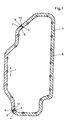
- FIGS. 1 and 2 An embodiment of the carrier according to the invention is in FIGS. 1 and 2 shown and will be described in more detail below.
- 1 and 2 is an embodiment of a carrier Flat gasket shown, which consists of a metallic material.
- the separately generated segments 1, 2 are in the area facing each other Ends 3, 5; 4, 6 positively connected.
- the positive connection is generated by projections 9, which are essentially dovetail-shaped and in the adjacent recesses 10 are inserted.
- the projections 9 are in their circumferential direction 7 Cross section expanded.
- the recesses 10 are congruent to the Projections 9 designed and have in the area of their mouths Cross-sectional narrowing.
- Both the projections 9 and the Recesses 10 are, based on an imaginary plane 8, the vertical stands on the support and extends in the longitudinal direction 7, in each case mirror image.
- the carrier for producing the Flat gasket Due to the composition of the carrier from several segments 1, 2 this is particularly dimensionally stable and has only a negligibly small manufacturing delay. Due to the pre-assembled unit, which is the two segments 1, 2 is formed, is the carrier for producing the Flat gasket easy to handle.
- the ready-to-use flat gasket is also very dimensionally stable and easy to assemble, in that the carrier through the segments 1, 2 hooked into one another in the circumferential direction 7 in a tensile manner are positively attached to each other, is endless.
- Fig. 2 the section "A" from Fig. 1 is shown enlarged.
- the segments 1, 2 are fixed to one another with their ends 4, 6.
- By hitting the two notches 11.1, 11.2 in this exemplary embodiment are the segments 1, 2 permanently connected.
- the notches 11 are hammered in when the segments are already are positively connected.
Abstract
Description
Die Erfindung betrifft einen Träger einer Flachdichtung, der aus zähhartem Werkstoff besteht und mit elastomerem Dichtungswerkstoff umspritzbar ist, umfassend zumindest zwei Segmente, die im Bereich ihrer einander zugewandten Enden miteinander verbunden sind.The invention relates to a carrier of a flat gasket made of tough hard Material exists and can be encapsulated with an elastomeric sealing material, comprising at least two segments in the area of each other facing ends are interconnected.
Ein derartiger Träger ist aus der DE 43 12 629 C1 bekannt. Der Träger ist als in Elastomermaterial eingeformte Blecheinlage ausgebildet und weist mehrere separat erzeugte Segmente auf, wobei die Segmente allein von dem elastomeren Dichtungswerkstoff zusammengehalten sind. Durch eine derartige Ausgestaltung des Trägers ist der Materialverlust bei seiner Herstellung sehr gering.Such a carrier is known from DE 43 12 629 C1. The carrier is as formed in elastomer material sheet metal insert and has several separately generated segments, the segments being solely from the elastomeric sealing material are held together. By such Design of the carrier is the loss of material in its manufacture very much low.
Der Erfindung liegt die Aufgabe zugrunde, einen Träger der eingangs genannten Art derart weiterzuentwickeln, daß dessen Handhabung bei der Herstellung der Flachdichtung vereinfacht wird und daß auch große Träger ohne Verzug ausstanzbar sind.The invention has for its object a carrier of the beginning mentioned type to develop such that its handling in the Manufacture of the flat gasket is simplified and that even large carriers can be punched out without delay.
Diese Aufgabe wird mit den Merkmalen von Anspruch 1 gelöst. Auf vorteilhafte
Ausgestaltungen nehmen die Unteransprüche Bezug.This object is achieved with the features of
Zur Lösung der Aufgabe ist es im Rahmen der vorliegenden Erfindung vorgesehen, daß die Enden formschlüssig aneinander festgelegt sind. Hierbei ist von Vorteil, daß sich der Träger, bestehend aus den einzelnen Segmenten, in seinen Gebrauchseigenschaften von einem einstückig hergestellten Träger nicht unterscheidet Da die Segmente im Anschluß an ihre Zusammenfügung ortsfest zueinander positioniert sind, ist die Herstellung der Flachdichtung besonders einfach, da der aus den Segmenten bestehende Träger als vormontierte Einheit in das Werkzeug einlegbar und mit elastomerem Dichtungswerkstoff umspritzbar ist. Ein Verschieben der einzelnen Segmente relativ zueinander ist während der Herstellung der Flachdichtung nicht möglich, so daß die Herstellung der Flachdichtung einfach und kostengünstig durchführbar ist.To achieve the object, it is within the scope of the present invention provided that the ends are positively attached to each other. in this connection is advantageous in that the carrier, consisting of the individual segments, in its use properties from a one-piece carrier does not distinguish since the segments following their joining are fixed to each other, is the manufacture of the flat gasket particularly simple because the carrier consisting of the segments as Pre-assembled unit can be inserted into the tool and with an elastomer Sealing material is extrusion-coated. Moving the individual segments relative to each other is not possible during the manufacture of the flat gasket, making the flat gasket simple and inexpensive is feasible.
Im Vergleich zu Trägern, die einstückig ausgebildet und als Ganzes ausgestanzt sind, ist bei dem erfindungsgemäßen Träger von Vorteil, daß der herstellungsbedingte Verzug des Trägers auf ein Minimum begrenzt ist.Compared to carriers that are integrally formed and as a whole are punched out, is advantageous in the carrier according to the invention that the manufacturing delay of the carrier is limited to a minimum.
Das Problem einstückig ausgebildeter Träger ist, daß sich das Bauteil wegen sein Größe durch den Stanzvorgang bogenförmig verzieht. Dieser Verzug hat zur Folge, daß ein einwandfreies Einlegen des Trägers in das Spritzgießwerkzeug erheblich erschwert wird. Eine Vielzahl der einstückig ausgestanzten Rahmen ist daher nicht mehr zu verarbeiten oder muß zeitaufwendig nachgerichtet werden. The problem of one-piece supports is that the component is due to its size warps through the punching process. This delay has the consequence that a correct insertion of the carrier in the Injection mold is made considerably more difficult. A variety of one piece punched frame is therefore no longer to be processed or must time consuming to be updated.
Durch das Ausstanzen von Segmenten, wobei mehrere Segmente in einem Arbeitsgang ausgestanzt werden können, und der anschließenden Zusammensetzung zum ganzen Träger, wird der zuvor beschriebene Verzug nahezu vollständig vermieden.By punching out segments, multiple segments in one Operation can be punched out, and the subsequent Composition to the whole carrier, the previously described delay almost completely avoided.
Der Materialverbrauch bei der Herstellung von Trägem aus Segmenten ist deutlich reduziert, da großflächige, ausgestanzte Innenteile, die anschließend verschrottet werden, wie bei der Herstellung einstückiger Träger, nicht mehr vorkommen.The material consumption in the production of supports from segments is significantly reduced because of large, punched out inner parts that then are no longer scrapped, as in the manufacture of one-piece girders occurrence.
Bei dem zähharten Werkstoff zur Herstellung der Segmente handelt es sich bevorzugt um metallische Werkstoffe, beispielsweise Blech. Der Träger ist daher kostengünstig herstellbar.The tough and hard material for the production of the segments is preferably around metallic materials, for example sheet metal. The carrier is therefore inexpensive to manufacture.
Die Enden sind in Umfangsrichtung zugfest ineinander eingehakt. Die Montage wird durch eine derartige Ausgestaltung sehr vereinfacht. Ein Lösen der Segmente ist auch während der Umspritzung des Trägers mit elastomerem Dichtungswerkstoff zuverlässig ausgeschlossen. Außerdem ist die Gefahr von Montagefehlern bei der Komplettierung der Segmente zum Träger auf ein Minimum begrenzt. Die unter Verwendung des erfindungsgemäßen Trägers hergestellten Flachdichtungen sind besonders maßhaltig.The ends are hooked into one another in the circumferential direction. The assembly is very simplified by such a configuration. Solving the Segments is also during the encapsulation of the carrier with elastomer Seal material reliably excluded. Besides, the danger of Assembly errors when completing the segments to the carrier on Minimum limited. The using the carrier according to the invention Flat gaskets produced are particularly true to size.
Bevorzugt ist jedes der Enden, bezogen auf eine gedachte, sich in Umfangsrichtung erstreckende, senkrecht auf dem Träger stehende Ebene spiegelbildlich ausgebildet. Dazu kann es vorgesehen sein, daß eines der einander benachbarten Enden mit einem in Umfangsrichtung vorstehenden Vorsprung versehen ist, der im vorspringenden Bereich in seinem Querschnitt erweitert ist und daß das angrenzende andere Ende eine in Umfangsrichtung zurückspringende, kongruent gestaltete, im Bereich ihrer Mündung eine Querschnittsverengung aufweisende Ausnehmung hat, in die der Vorsprung einrastbar ist. Der Vorsprung kann beispielsweise im wesentlichen schwalbenschwanzförmig ausgebildet sein. Derartige, symmetrisch zu der Ebene ausgebildete Vorsprünge und Ausnehmungen sind durch Stanzen besonders einfach und exakt herstellbar. Die Montage der Segmente miteinander erfolgt derart, daß deren Enden überlappend zueinander positioniert werden und der Vorsprung und die Ausnehmung anschließend ineinander eingeschnappt werden. Durch die zur Umfangsrichtung symmetrische Ausgestaltung der Enden zentrieren diese sich während der Montage von selbst. Die Positionierung der Segmente zueinander, sowohl in als auch quer zur Längsrichtung ist daher besonders gut.Each of the ends, based on an imaginary one, is preferably in Plane extending circumferentially, perpendicular to the support mirror image. For this purpose, it can be provided that one of the mutually adjacent ends with a protruding circumferentially Is provided protrusion in the projecting area in its cross section is expanded and that the adjacent other end is a circumferential recessed, congruently designed, in the area of their mouth one Has cross-sectional narrowing recess in which the projection can be snapped into place. The protrusion can, for example, essentially be dovetail-shaped. Such, symmetrical to that Flat projections and recesses are made by punching particularly easy and precise to manufacture. The assembly of the segments with each other is such that their ends overlap each other be positioned and then the projection and the recess snapped into each other. By the to the circumferential direction symmetrical design of the ends center them during the Assembly by itself. The positioning of the segments to each other, both in as well as transverse to the longitudinal direction is therefore particularly good.
Zusätzlich kann es vorgesehen sein, daß der Vorsprung des einen Endes und der Werkstoff des die Ausnehmung begrenzenden anderen Endes zumindest einerseits des Trägers zumindest eine ineinanderübergehende Kerbe aufweisen. Durch die plastische Verformung sowohl des Werkstoffs des Vorsprungs als auch des Werkstoffs, der die Ausnehmung begrenzt, wird ein Widerhakeneffekt erzielt, so daß die Enden der Segmente unlösbar miteinander verbunden sind.In addition, it can be provided that the projection of one end and the material of the other end delimiting the recess at least on the one hand, the carrier has at least one merging notch exhibit. Due to the plastic deformation of both the material of the Projection as well as the material that delimits the recess becomes a Barb effect achieved so that the ends of the segments are unsolvable are interconnected.
Der erfindungsgemäße Träger findet bevorzugt in einer Flachdichtung Anwendung, die z.B. als Ölwannendichtung ausgebildet sein kann.The carrier according to the invention is preferably found in a flat gasket Application that e.g. can be designed as an oil pan gasket.
Ein Ausführungsbeispiel des erfindungsgemäßen Träger ist in den Fig. 1 und 2 gezeigt und wird nachfolgend näher beschrieben. An embodiment of the carrier according to the invention is in FIGS. 1 and 2 shown and will be described in more detail below.
Es zeigen:
In den Fig. 1 und 2 ist ein Ausführungsbeispiel eines Trägers einer
Flachdichtung gezeigt, der aus einem metallischen Werkstoff besteht. Die
separat erzeugten Segmente 1, 2 sind im Bereich ihrer einander zugewandten
Enden 3, 5; 4, 6 formschlüssig miteinander verbunden.1 and 2 is an embodiment of a carrier
Flat gasket shown, which consists of a metallic material. The
separately generated
Der Formschluß wird durch Vorsprünge 9 erzeugt, die im wesentlichen
schwalbenschwanzförmig ausgebildet und in die benachbarten Ausnehmungen
10 eingefügt sind. Die Vorsprünge 9 sind in Umfangsrichtung 7 in ihrem
Querschnitt erweitert. Die Ausnehmungen 10 sind kongruent zu den
Vorsprüngen 9 gestaltet und weisen im Bereich ihrer Mündungen eine
Querschnittsverengung auf. Sowohl die Vorsprünge 9 als auch die
Ausnehmungen 10 sind, bezogen auf eine gedachte Ebene 8, die senkrecht
auf dem Träger steht und sich in Längsrichtung 7 erstreckt, jeweils
spiegelbildlich ausgebildet.The positive connection is generated by
Durch die Zusammensetzung des Trägers aus mehreren Segmenten 1, 2 ist
dieser besonders formstabil und weist nur einen vemachlässigbar geringen,
herstellungsbedingten Verzug auf. Durch die vormontierbare Einheit, die durch
die beiden Segmente 1, 2 gebildet ist, ist der Träger zur Herstellung der
Flachdichtung gut handhabbar. Die gebrauchsfertige Flachdichtung ist
ebenfalls sehr maßhaltig und gut montierbar, dadurch, daß der Träger durch
die in Umfangsrichtung 7 zugfest ineinander eingehakten Segmente 1, 2 die
formschlüssig aneinander festgelegt sind, endlos ausgebildet ist. Due to the composition of the carrier from
In Fig. 2 ist der Ausschnitt "A" aus Fig. 1 vergrößert dargestellt. Die Segmente
1, 2 sind mit ihren Enden 4, 6 aneinander festgelegt. Durch das Einschlagen
der in diesem Ausführungsbeispiel zwei Kerben 11.1, 11.2, sind die Segmente
1, 2 unlösbar miteinander verbunden.In Fig. 2, the section "A" from Fig. 1 is shown enlarged. The
Die Kerben 11 werden eingeschlagen, wenn die Segmente bereits formschlüssig miteinander verbunden sind.The notches 11 are hammered in when the segments are already are positively connected.
Claims (6)
- A support of a gasket which consists of tough material and can be encapsulated in elastomeric sealing material, comprising at least two segments (1, 2), which are connected to each other in the region of their mutually facing ends (3, 5; 4, 6), characterized in that the ends (3, 5; 4, 6) are fixed against each other with positive engagement.
- A support according to claim 1, characterized in that the ends (3, 5; 4, 6) are hooked in each other to resist tension in the circumferential direction (7).
- A support according to either of claims 1 and 2, characterized in that each end (3, 4; 5, 6) is formed mirror-invertedly with respect to an imaginary plane (8) extending in the circumferential direction (7) and perpendicular to the support.
- A support according to any one of claims 1 to 3, characterized in that one of the mutually adjacent ends (3, 5; 4, 6) is provided with a projection (9) which projects in the circumferential direction (7) and, in the projecting region, is widened in its cross section and in that the adjacent other end (5, 3; 6, 4) has a congruently shaped clearance (10) which is set back in the circumferential direction (7), has a cross-sectional constriction in the region of its opening and into which the projection (9) can be clipped.
- A support according to claim 4, characterized in that the projection (9) is formed substantially in a dovetail-shaped manner.
- A support according to either of claims 4 and 5, characterized in that the projection (9) of one end (3, 5; 4, 6) and the material of the other end (5, 3; 6, 4), adjacent to the clearance (10), have at least on one side of the support at least one merging notch (11).
Applications Claiming Priority (2)
| Application Number | Priority Date | Filing Date | Title |
|---|---|---|---|
| DE19739196 | 1997-09-08 | ||
| DE19739196A DE19739196C2 (en) | 1997-09-08 | 1997-09-08 | Carrier of a flat gasket |
Publications (2)
| Publication Number | Publication Date |
|---|---|
| EP0900929A1 EP0900929A1 (en) | 1999-03-10 |
| EP0900929B1 true EP0900929B1 (en) | 2002-12-04 |
Family
ID=7841528
Family Applications (1)
| Application Number | Title | Priority Date | Filing Date |
|---|---|---|---|
| EP98116759A Expired - Lifetime EP0900929B1 (en) | 1997-09-08 | 1998-09-04 | Support of a gasket |
Country Status (3)
| Country | Link |
|---|---|
| EP (1) | EP0900929B1 (en) |
| AT (1) | ATE229125T1 (en) |
| DE (2) | DE19739196C2 (en) |
Cited By (4)
| Publication number | Priority date | Publication date | Assignee | Title |
|---|---|---|---|---|
| US7229548B2 (en) | 1997-07-15 | 2007-06-12 | Exxonmobil Research And Engineering Company | Process for upgrading naphtha |
| US7232515B1 (en) | 1997-07-15 | 2007-06-19 | Exxonmobil Research And Engineering Company | Hydrofining process using bulk group VIII/Group VIB catalysts |
| US7288182B1 (en) | 1997-07-15 | 2007-10-30 | Exxonmobil Research And Engineering Company | Hydroprocessing using bulk Group VIII/Group VIB catalysts |
| US7513989B1 (en) | 1997-07-15 | 2009-04-07 | Exxonmobil Research And Engineering Company | Hydrocracking process using bulk group VIII/Group VIB catalysts |
Families Citing this family (7)
| Publication number | Priority date | Publication date | Assignee | Title |
|---|---|---|---|---|
| DE19922484B4 (en) * | 1999-05-15 | 2005-03-10 | Greiner Gmbh | gasket |
| DE102004035285A1 (en) * | 2004-07-21 | 2006-02-16 | Federal-Mogul Sealing Systems Bretten Gmbh | Process for producing carrier elements for elastomeric seals |
| JP4887037B2 (en) | 2005-12-07 | 2012-02-29 | 内山工業株式会社 | Gasket manufacturing method and gasket |
| CN106438102A (en) * | 2016-11-08 | 2017-02-22 | 天津雷沃发动机有限公司 | Seal structure of engine timing chamber cover plate |
| DE102021106636A1 (en) | 2021-03-18 | 2022-09-22 | Carl Freudenberg Kg | flat gasket |
| DE102022200844B3 (en) | 2022-01-26 | 2023-07-06 | Zf Friedrichshafen Ag | Process for manufacturing a sealing ring |
| DE202022103142U1 (en) | 2022-06-02 | 2023-09-08 | Reinz-Dichtungs-Gmbh | poetry |
Family Cites Families (9)
| Publication number | Priority date | Publication date | Assignee | Title |
|---|---|---|---|---|
| US1986465A (en) * | 1933-12-20 | 1935-01-01 | Westinghouse Air Brake Co | Gasket construction |
| US3175832A (en) * | 1963-04-26 | 1965-03-30 | Parker Hannifin Corp | Sealing gasket |
| US3738670A (en) * | 1971-09-27 | 1973-06-12 | Parker Hannifin Corp | Sectional gasket |
| IT8434064V0 (en) * | 1984-10-22 | 1984-10-22 | Zanussi Elettrodomestici | GASKET, IN PARTICULAR FOR HOUSEHOLD APPLIANCES. |
| US4572522A (en) * | 1985-05-06 | 1986-02-25 | Felt Products Mfg. Co. | Interlocking sectional gasket assembly and method of making same |
| FR2659122B1 (en) * | 1990-03-02 | 1993-10-22 | Procal | FLAT GASKET. |
| AU660458B2 (en) * | 1991-05-17 | 1995-06-29 | Tokyo Gasket Co. Ltd. | Split-type gasket |
| DE4312629C1 (en) * | 1993-04-19 | 1994-11-03 | Bruss Dichtungstechnik | Elastomeric gasket |
| DE4425206C1 (en) * | 1994-07-16 | 1995-10-12 | Gloeckler Dichtungen Guenter H | Motor valve housing seal for simple and effective sealing lip bonding |
-
1997
- 1997-09-08 DE DE19739196A patent/DE19739196C2/en not_active Expired - Lifetime
-
1998
- 1998-09-04 AT AT98116759T patent/ATE229125T1/en active
- 1998-09-04 EP EP98116759A patent/EP0900929B1/en not_active Expired - Lifetime
- 1998-09-04 DE DE59806504T patent/DE59806504D1/en not_active Expired - Lifetime
Cited By (4)
| Publication number | Priority date | Publication date | Assignee | Title |
|---|---|---|---|---|
| US7229548B2 (en) | 1997-07-15 | 2007-06-12 | Exxonmobil Research And Engineering Company | Process for upgrading naphtha |
| US7232515B1 (en) | 1997-07-15 | 2007-06-19 | Exxonmobil Research And Engineering Company | Hydrofining process using bulk group VIII/Group VIB catalysts |
| US7288182B1 (en) | 1997-07-15 | 2007-10-30 | Exxonmobil Research And Engineering Company | Hydroprocessing using bulk Group VIII/Group VIB catalysts |
| US7513989B1 (en) | 1997-07-15 | 2009-04-07 | Exxonmobil Research And Engineering Company | Hydrocracking process using bulk group VIII/Group VIB catalysts |
Also Published As
| Publication number | Publication date |
|---|---|
| EP0900929A1 (en) | 1999-03-10 |
| DE19739196C2 (en) | 1999-12-30 |
| ATE229125T1 (en) | 2002-12-15 |
| DE59806504D1 (en) | 2003-01-16 |
| DE19739196A1 (en) | 1999-03-25 |
Similar Documents
| Publication | Publication Date | Title |
|---|---|---|
| EP2054648B1 (en) | Sealing or corrugated bellows | |
| DE3509923C2 (en) | Spring element | |
| EP0900929B1 (en) | Support of a gasket | |
| DE3203602A1 (en) | SHARED PLASTIC COVER | |
| DE4122455A1 (en) | Push-in connection for thermoplastic pipes - has ring with differently inclined flaps forming seal between connecting faces | |
| DE60115675T2 (en) | CYLINDER HEAD GASKET WITH VARIATING RESTRICTIVE RING THICKNESS AND METHOD FOR FIXING THE LIMIT RING | |
| DE3035170C2 (en) | Seal for valves | |
| DE60017217T2 (en) | Rod for limiting the relative movement between two rigid elements | |
| EP3452734B1 (en) | Clip for securing a first element to a second element | |
| DE3423967A1 (en) | Profile element | |
| DE19630152C1 (en) | Positive connection for long seal in internal combustion engines | |
| DE102006045325B4 (en) | meter housing | |
| DE10353040B4 (en) | Flat seal with fixing device | |
| DE60010407T2 (en) | Sealing ring with double sealing line and method for evaluating the functioning of such a ring | |
| EP3839299A1 (en) | Radial shaft seal, bellows flange and assembly method for same | |
| DE60203119T2 (en) | CYLINDER HEAD GASKET WITH A EDGE TO RIM STOP RING | |
| DE102016220022A1 (en) | Combination of a plug with a lid | |
| DE19517217C2 (en) | Solid window cage for a needle bearing | |
| DE3309409A1 (en) | Fastening device | |
| DE3222301A1 (en) | Radiator, preferably for an internal-combustion engine | |
| DE102008041829A1 (en) | Articular connection arrangement in a windshield wiper device | |
| DE202005006411U1 (en) | Flat metal gasket with holding tabs for sealing joint has outer edge of main seal with projections | |
| DE2623349C2 (en) | Guide device for the fishing line on fishing rods | |
| DE102017200510A1 (en) | Flat gasket with adhesion optimization | |
| DE3518866C1 (en) | Bolt parts for forming a self-locking blocking bolt |
Legal Events
| Date | Code | Title | Description |
|---|---|---|---|
| PUAI | Public reference made under article 153(3) epc to a published international application that has entered the european phase |
Free format text: ORIGINAL CODE: 0009012 |
|
| AK | Designated contracting states |
Kind code of ref document: A1 Designated state(s): AT DE FR GB IT |
|
| AX | Request for extension of the european patent |
Free format text: AL;LT;LV;MK;RO;SI |
|
| 17P | Request for examination filed |
Effective date: 19990112 |
|
| AKX | Designation fees paid |
Free format text: AT DE FR GB IT |
|
| RAP1 | Party data changed (applicant data changed or rights of an application transferred) |
Owner name: CARL FREUDENBERG KG |
|
| GRAG | Despatch of communication of intention to grant |
Free format text: ORIGINAL CODE: EPIDOS AGRA |
|
| GRAG | Despatch of communication of intention to grant |
Free format text: ORIGINAL CODE: EPIDOS AGRA |
|
| GRAH | Despatch of communication of intention to grant a patent |
Free format text: ORIGINAL CODE: EPIDOS IGRA |
|
| 17Q | First examination report despatched |
Effective date: 20020607 |
|
| GRAH | Despatch of communication of intention to grant a patent |
Free format text: ORIGINAL CODE: EPIDOS IGRA |
|
| GRAA | (expected) grant |
Free format text: ORIGINAL CODE: 0009210 |
|
| AK | Designated contracting states |
Kind code of ref document: B1 Designated state(s): AT DE FR GB IT |
|
| REF | Corresponds to: |
Ref document number: 229125 Country of ref document: AT Date of ref document: 20021215 Kind code of ref document: T |
|
| REG | Reference to a national code |
Ref country code: GB Ref legal event code: FG4D Free format text: NOT ENGLISH |
|
| REF | Corresponds to: |
Ref document number: 59806504 Country of ref document: DE Date of ref document: 20030116 |
|
| GBT | Gb: translation of ep patent filed (gb section 77(6)(a)/1977) |
Effective date: 20021230 |
|
| ET | Fr: translation filed | ||
| PLBE | No opposition filed within time limit |
Free format text: ORIGINAL CODE: 0009261 |
|
| STAA | Information on the status of an ep patent application or granted ep patent |
Free format text: STATUS: NO OPPOSITION FILED WITHIN TIME LIMIT |
|
| 26N | No opposition filed |
Effective date: 20030905 |
|
| REG | Reference to a national code |
Ref country code: FR Ref legal event code: PLFP Year of fee payment: 19 |
|
| REG | Reference to a national code |
Ref country code: FR Ref legal event code: PLFP Year of fee payment: 20 |
|
| PGFP | Annual fee paid to national office [announced via postgrant information from national office to epo] |
Ref country code: FR Payment date: 20170920 Year of fee payment: 20 Ref country code: IT Payment date: 20170929 Year of fee payment: 20 Ref country code: GB Payment date: 20170921 Year of fee payment: 20 |
|
| PGFP | Annual fee paid to national office [announced via postgrant information from national office to epo] |
Ref country code: AT Payment date: 20170921 Year of fee payment: 20 |
|
| PGFP | Annual fee paid to national office [announced via postgrant information from national office to epo] |
Ref country code: DE Payment date: 20170928 Year of fee payment: 20 |
|
| REG | Reference to a national code |
Ref country code: DE Ref legal event code: R071 Ref document number: 59806504 Country of ref document: DE |
|
| REG | Reference to a national code |
Ref country code: GB Ref legal event code: PE20 Expiry date: 20180903 |
|
| REG | Reference to a national code |
Ref country code: AT Ref legal event code: MK07 Ref document number: 229125 Country of ref document: AT Kind code of ref document: T Effective date: 20180904 |
|
| PG25 | Lapsed in a contracting state [announced via postgrant information from national office to epo] |
Ref country code: GB Free format text: LAPSE BECAUSE OF EXPIRATION OF PROTECTION Effective date: 20180903 |