EP0899804A1 - Verfahren zur Herstellung einem aufgeweitete Gitter und Vorrichtung dafür - Google Patents
Verfahren zur Herstellung einem aufgeweitete Gitter und Vorrichtung dafür Download PDFInfo
- Publication number
- EP0899804A1 EP0899804A1 EP98306445A EP98306445A EP0899804A1 EP 0899804 A1 EP0899804 A1 EP 0899804A1 EP 98306445 A EP98306445 A EP 98306445A EP 98306445 A EP98306445 A EP 98306445A EP 0899804 A1 EP0899804 A1 EP 0899804A1
- Authority
- EP
- European Patent Office
- Prior art keywords
- region
- cuts
- thin plate
- grid
- central portion
- Prior art date
- Legal status (The legal status is an assumption and is not a legal conclusion. Google has not performed a legal analysis and makes no representation as to the accuracy of the status listed.)
- Granted
Links
Images




Classifications
-
- H—ELECTRICITY
- H01—ELECTRIC ELEMENTS
- H01M—PROCESSES OR MEANS, e.g. BATTERIES, FOR THE DIRECT CONVERSION OF CHEMICAL ENERGY INTO ELECTRICAL ENERGY
- H01M4/00—Electrodes
- H01M4/02—Electrodes composed of, or comprising, active material
- H01M4/64—Carriers or collectors
- H01M4/70—Carriers or collectors characterised by shape or form
- H01M4/72—Grids
- H01M4/74—Meshes or woven material; Expanded metal
- H01M4/745—Expanded metal
-
- H—ELECTRICITY
- H01—ELECTRIC ELEMENTS
- H01M—PROCESSES OR MEANS, e.g. BATTERIES, FOR THE DIRECT CONVERSION OF CHEMICAL ENERGY INTO ELECTRICAL ENERGY
- H01M4/00—Electrodes
- H01M4/02—Electrodes composed of, or comprising, active material
- H01M4/64—Carriers or collectors
- H01M4/66—Selection of materials
- H01M4/68—Selection of materials for use in lead-acid accumulators
-
- H—ELECTRICITY
- H01—ELECTRIC ELEMENTS
- H01M—PROCESSES OR MEANS, e.g. BATTERIES, FOR THE DIRECT CONVERSION OF CHEMICAL ENERGY INTO ELECTRICAL ENERGY
- H01M4/00—Electrodes
- H01M4/02—Electrodes composed of, or comprising, active material
- H01M4/64—Carriers or collectors
- H01M4/66—Selection of materials
- H01M4/68—Selection of materials for use in lead-acid accumulators
- H01M4/685—Lead alloys
-
- H—ELECTRICITY
- H01—ELECTRIC ELEMENTS
- H01M—PROCESSES OR MEANS, e.g. BATTERIES, FOR THE DIRECT CONVERSION OF CHEMICAL ENERGY INTO ELECTRICAL ENERGY
- H01M4/00—Electrodes
- H01M4/02—Electrodes composed of, or comprising, active material
- H01M4/64—Carriers or collectors
- H01M4/82—Multi-step processes for manufacturing carriers for lead-acid accumulators
-
- Y—GENERAL TAGGING OF NEW TECHNOLOGICAL DEVELOPMENTS; GENERAL TAGGING OF CROSS-SECTIONAL TECHNOLOGIES SPANNING OVER SEVERAL SECTIONS OF THE IPC; TECHNICAL SUBJECTS COVERED BY FORMER USPC CROSS-REFERENCE ART COLLECTIONS [XRACs] AND DIGESTS
- Y02—TECHNOLOGIES OR APPLICATIONS FOR MITIGATION OR ADAPTATION AGAINST CLIMATE CHANGE
- Y02E—REDUCTION OF GREENHOUSE GAS [GHG] EMISSIONS, RELATED TO ENERGY GENERATION, TRANSMISSION OR DISTRIBUTION
- Y02E60/00—Enabling technologies; Technologies with a potential or indirect contribution to GHG emissions mitigation
- Y02E60/10—Energy storage using batteries
-
- Y—GENERAL TAGGING OF NEW TECHNOLOGICAL DEVELOPMENTS; GENERAL TAGGING OF CROSS-SECTIONAL TECHNOLOGIES SPANNING OVER SEVERAL SECTIONS OF THE IPC; TECHNICAL SUBJECTS COVERED BY FORMER USPC CROSS-REFERENCE ART COLLECTIONS [XRACs] AND DIGESTS
- Y10—TECHNICAL SUBJECTS COVERED BY FORMER USPC
- Y10T—TECHNICAL SUBJECTS COVERED BY FORMER US CLASSIFICATION
- Y10T29/00—Metal working
- Y10T29/10—Battery-grid making
-
- Y—GENERAL TAGGING OF NEW TECHNOLOGICAL DEVELOPMENTS; GENERAL TAGGING OF CROSS-SECTIONAL TECHNOLOGIES SPANNING OVER SEVERAL SECTIONS OF THE IPC; TECHNICAL SUBJECTS COVERED BY FORMER USPC CROSS-REFERENCE ART COLLECTIONS [XRACs] AND DIGESTS
- Y10—TECHNICAL SUBJECTS COVERED BY FORMER USPC
- Y10T—TECHNICAL SUBJECTS COVERED BY FORMER US CLASSIFICATION
- Y10T29/00—Metal working
- Y10T29/18—Expanded metal making
-
- Y—GENERAL TAGGING OF NEW TECHNOLOGICAL DEVELOPMENTS; GENERAL TAGGING OF CROSS-SECTIONAL TECHNOLOGIES SPANNING OVER SEVERAL SECTIONS OF THE IPC; TECHNICAL SUBJECTS COVERED BY FORMER USPC CROSS-REFERENCE ART COLLECTIONS [XRACs] AND DIGESTS
- Y10—TECHNICAL SUBJECTS COVERED BY FORMER USPC
- Y10T—TECHNICAL SUBJECTS COVERED BY FORMER US CLASSIFICATION
- Y10T29/00—Metal working
- Y10T29/18—Expanded metal making
- Y10T29/185—Expanded metal making by use of reciprocating perforator
-
- Y—GENERAL TAGGING OF NEW TECHNOLOGICAL DEVELOPMENTS; GENERAL TAGGING OF CROSS-SECTIONAL TECHNOLOGIES SPANNING OVER SEVERAL SECTIONS OF THE IPC; TECHNICAL SUBJECTS COVERED BY FORMER USPC CROSS-REFERENCE ART COLLECTIONS [XRACs] AND DIGESTS
- Y10—TECHNICAL SUBJECTS COVERED BY FORMER USPC
- Y10T—TECHNICAL SUBJECTS COVERED BY FORMER US CLASSIFICATION
- Y10T29/00—Metal working
- Y10T29/49—Method of mechanical manufacture
- Y10T29/49002—Electrical device making
- Y10T29/49108—Electric battery cell making
Definitions
- the present invention relates to a manufacturing method of expanded grid used in a storage battery, and a manufacturing apparatus of expanded grid.
- an expanded grid used as the core of an electrode of a storage battery is manufactured in a step of forming parallel intermittent cuts in the width direction in a surface of a region excluding the central portion of a thin plate in a band form made of metal such as lead or lead alloy continuously in a zigzag form, and a step of expanding and developing the thin plate having cuts in the width direction.
- the expanded grid used widely as the grid for electrode plates of a lead acid storage battery is superior to the casting grid in the mass producibility, and is suited to the lead acid storage batteries of mass-produced automobiles. Recently, a higher performance is demanded in the batteries, and it is required to reduce the mesh size of the grid in order to enhance the current collecting effect of the grid.
- a manufacturing method of expanded grid of the invention includes:
- the manufacturing method further includes:
- the second region is a central portion of the thin plate of band form
- the first region is both side portions of the central portion
- the central portion is bent at a position for terminating the expansion of the outermost side portion.
- a manufacturing apparatus of expanded grid of the invention includes:
- the setting means is bending means for bending the second region at a desired angle.
- the second region is a central portion of the thin plate of band form
- the first region is both side portions of the central portion
- the central portion is bent at a position for terminating the expansion of the outermost side portion.
- Fig. 1 is a side view of a manufacturing apparatus used in a manufacturing method of expanded grid in an embodiment of the invention.
- Fig. 2 is a process chart of a manufacturing method of an expanded grid in an embodiment of the invention.
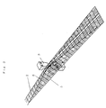
- Fig. 3 is a position configuration diagram of solid development in a manufacturing method of an expanded grid in an embodiment of the invention.
- Fig. 4 is a plan view of an expanded grid manufactured by a manufacturing method of an expanded grid in an embodiment of the invention.
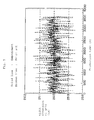
- Fig. 5 is a graph showing the relation between production time in production and the width dimension of the expanded grid.
- Fig. 6 is a graph showing the relation between the overcharge amount and life frequency of the storage battery using the expanded grids of an embodiment and a prior art.
- Fig. 7 is a position configuration diagram of plane development in a manufacturing method of an expanded grid in a prior art.
- FIG. 1 A side view of an apparatus of an embodiment used in a manufacturing method of an expanded grid of the invention is shown in Fig. 1.
- the manufacturing apparatus of grid includes a processing blade 1, bending means 3, and a base 4 as processing means.
- the processing blade 1 has about 30 blades.
- a thin film 2 of band form moves the lower side of the processing blade 1 in the longitudinal direction.
- the thin plate 2 moves in synchronism with the processing blade 1 and bending means 3.
- cuts are formed in the thin plate 2 of band form in a mesh pattern.
- the thin plate 2 of band form is composed of lead-tin-calcium alloy, and its thickness is about 1.0 mm.
- the thin plate 2 having mesh pattern cuts is expanded and developed in the width direction of the thin plate 2.
- the bending means 3 of hammer shape is disposed at the terminating position of expansion of the outermost side portion of the thin plate 2 expanding and developing the cuts in the width direction.
- the bending means 3 bends only the central portion of the thin plate where cuts are not formed.
- the bending means moves reciprocally in the vertical direction in synchronism with the processing blade 1.
- the base 4 is fixed so as to support the bending means 3 still at its position. When the thin plate 2 is pushed and bent by the bending means 3, the base 4 plays a role of controlling its bending angle.
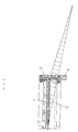
- Fig. 7 shows the position configuration diagram of plane development of forming cuts in the thin plate 2 of band form, and sequentially expanding and developing in the width direction.
- the outermost side portion of the thin plate 2 in band form having cuts in mesh pattern advances a track 15, and the central portion advances a track 16.
- the track distance of the outermost side portion from the point of starting expansion of the cuts in mesh pattern until the point of terminating the expansion is about 510 mm, and the track distance of the central portion is about 495 mm.
- the track distance of the outermost side portion is longer than the track distance of the central portion by about 15 mm, and a plane distortion 7 occurs as shown in the shaded area due to this difference in the track distance. Owing to such distortion, creases were formed in the obtained expanded grid . Besides, the skeleton of the grid was bent, and a local stress concentration occurred originating from the deflection of the skeleton.
- FIG. 2 An embodiment of the invention is described below while referring to Fig. 2.
- the process chart of the manufacturing method of the grid in an embodiment of the invention is shown in Fig. 2.
- the thin plate 2 of band form is put at the lower side of the processing blade 1 as processing means of the manufacturing apparatus of the grid shown in Fig. 1 and the bending machine 3 as the bending means.
- the processing blade 1 is moved up and down, and the central portion of the thin plate 2 is bent at a desired angle.
- the bending machine 3 By setting the bending machine 3 in a desired shape, the thin plate can be bent three-dimensionally. In this embodiment, the deflection angle is about 17 degrees.
- the thin plate 2 having the cut region and the uncut region is sequentially moved in the longitudinal direction, and the cuts are expanded and developed in the width direction.
- it is designed to develop by expanding three-dimensionally.
- the track distance 5 of the outermost side portion of the thin plate 2 of band form is shorter than in the case not having bent state. That is, the track distance 5 of the outermost side portion of the thin plate 2 of band form is nearly same distance as the track distance 6 of the central portion.
- Fig. 5 The relation between the production time and width dimension changes of the grid in production of expanded grid is shown in Fig. 5.
- the solid line refers to this embodiment, and the broken line shows a prior art. Fluctuations of the width dimension of the solid line showing the embodiment are about 1/3 of fluctuations of the broken line showing the prior art. That is, the grid formed in this embodiment is stable in the width dimension. Moreover, fluctuations of cutting dimension in the process of cutting off the thin plate can be also decreased. Still more, the manufacturing conditions can be controlled easily, and the paste filling amount in the later process of filling with the paste containing active material can be also controlled easily.
- the skeleton of the grid was bent by a plane distortion 7 indicated by shaded area in Fig. 7, and a local stress concentration was initiated from the deflection of this skeleton, but occurrence of such local stress concentration was decreased in the invention.
- Fig. 6 shows the frequency distribution of overcharge amount per weight of grid at the end of grid life.
- the overcharge amount per weight of the grid is (charge amount per charge) x (number of cycles) / (grid weight).
- the life of the grid was judged when the discharge capacity became 80% of the initial capacity.
- the battery life began to be found from the overcharge amount of about 5 Ah/g, and the life was over in certain batteries even when the overcharge amount was small.
- the distribution width (variance) of the overcharge amount was in a range of about 5 Ah/g to about 12 Ah/g, and the distribution width of the overcharge amount was large.
- Such early life of batter at small overcharge amount was mainly caused by corrosion at the crease location of the grid.
- the battery life began to be found from the overcharge amount of about 7 Ah/g, and the life was over in some batteries at a larger overcharge amount than in the batteries using the conventional grids. Further, the distribution width (variance) of the overcharge amount was in a range of about 7 Ah/g to about 12 Ah/g, and the distribution width of the overcharge amount was small. That is, in the batteries using the grid of the invention, the life was extremely improved as compared with the batteries using the conventional grids. The batteries using the grids of the invention have a stable charge performance.
- cuts were formed by vertical reciprocating motion, but not limited this method, same effects are obtained in a manufacturing method of expanded grid by forming cuts by means of, for example, a rotating element.
- the thin plate of band form is not particularly limited, but lead or lead alloy can be used, and a particularly excellent lead acid storage battery is obtained in such a case.
- the plane distortion of the grid is eliminated, the width dimension of the grid is stable, and the quality of the electrode plate using such grid is enhanced. Further, local stress concentration of the grid is suppressed.
Landscapes
- Chemical & Material Sciences (AREA)
- Chemical Kinetics & Catalysis (AREA)
- Electrochemistry (AREA)
- General Chemical & Material Sciences (AREA)
- Cell Electrode Carriers And Collectors (AREA)
- Battery Electrode And Active Subsutance (AREA)
Applications Claiming Priority (2)
| Application Number | Priority Date | Filing Date | Title |
|---|---|---|---|
| JP23207497A JP3496472B2 (ja) | 1997-08-28 | 1997-08-28 | エキスパンド格子体の製造法 |
| JP232074/97 | 1997-08-28 |
Publications (2)
| Publication Number | Publication Date |
|---|---|
| EP0899804A1 true EP0899804A1 (de) | 1999-03-03 |
| EP0899804B1 EP0899804B1 (de) | 2006-05-03 |
Family
ID=16933591
Family Applications (1)
| Application Number | Title | Priority Date | Filing Date |
|---|---|---|---|
| EP98306445A Expired - Lifetime EP0899804B1 (de) | 1997-08-28 | 1998-08-13 | Verfahren zur Herstellung einem aufgeweitete Gitter und Vorrichtung dafür |
Country Status (7)
| Country | Link |
|---|---|
| US (1) | US6243932B1 (de) |
| EP (1) | EP0899804B1 (de) |
| JP (1) | JP3496472B2 (de) |
| KR (1) | KR100276962B1 (de) |
| CN (1) | CN1133223C (de) |
| DE (1) | DE69834369T2 (de) |
| TW (1) | TW535315B (de) |
Families Citing this family (2)
| Publication number | Priority date | Publication date | Assignee | Title |
|---|---|---|---|---|
| JP4570168B2 (ja) * | 2003-08-06 | 2010-10-27 | シエル・インターナシヨネイル・リサーチ・マーチヤツピイ・ベー・ウイ | 展伸金属 |
| CN109256046B (zh) * | 2018-09-20 | 2021-08-10 | 昆山国显光电有限公司 | 一种显示面板及其制备方法 |
Citations (5)
| Publication number | Priority date | Publication date | Assignee | Title |
|---|---|---|---|---|
| US3867200A (en) * | 1973-09-20 | 1975-02-18 | Gen Motors Corp | Method and apparatus for making oxidized expanded lead battery grids |
| US4221032A (en) * | 1979-04-04 | 1980-09-09 | Cousino Impact Corporation | Method of forming expanded metal grids particularly lead grids for storage battery plates |
| US4303747A (en) * | 1979-12-19 | 1981-12-01 | Firma Emil Bender | Expanded-metal grid |
| GB2200069A (en) * | 1986-12-30 | 1988-07-27 | Magneti Marelli Spa | A machine for producing a strip of metal-alloy or plastics grating for use in the manufacture of accumulator plates |
| EP0682378A1 (de) * | 1992-12-28 | 1995-11-15 | Yuasa Corporation | Aufgeweitetes netz, verfahren zu dessen herstellung und platte für bleiakku |
-
1997
- 1997-08-28 JP JP23207497A patent/JP3496472B2/ja not_active Expired - Lifetime
-
1998
- 1998-08-13 EP EP98306445A patent/EP0899804B1/de not_active Expired - Lifetime
- 1998-08-13 DE DE69834369T patent/DE69834369T2/de not_active Expired - Lifetime
- 1998-08-25 TW TW087114014A patent/TW535315B/zh not_active IP Right Cessation
- 1998-08-26 CN CN98118535A patent/CN1133223C/zh not_active Expired - Lifetime
- 1998-08-26 KR KR1019980034736A patent/KR100276962B1/ko not_active Expired - Lifetime
- 1998-08-27 US US09/141,215 patent/US6243932B1/en not_active Expired - Lifetime
Patent Citations (5)
| Publication number | Priority date | Publication date | Assignee | Title |
|---|---|---|---|---|
| US3867200A (en) * | 1973-09-20 | 1975-02-18 | Gen Motors Corp | Method and apparatus for making oxidized expanded lead battery grids |
| US4221032A (en) * | 1979-04-04 | 1980-09-09 | Cousino Impact Corporation | Method of forming expanded metal grids particularly lead grids for storage battery plates |
| US4303747A (en) * | 1979-12-19 | 1981-12-01 | Firma Emil Bender | Expanded-metal grid |
| GB2200069A (en) * | 1986-12-30 | 1988-07-27 | Magneti Marelli Spa | A machine for producing a strip of metal-alloy or plastics grating for use in the manufacture of accumulator plates |
| EP0682378A1 (de) * | 1992-12-28 | 1995-11-15 | Yuasa Corporation | Aufgeweitetes netz, verfahren zu dessen herstellung und platte für bleiakku |
Also Published As
| Publication number | Publication date |
|---|---|
| HK1018359A1 (zh) | 1999-12-17 |
| US6243932B1 (en) | 2001-06-12 |
| JP3496472B2 (ja) | 2004-02-09 |
| DE69834369D1 (de) | 2006-06-08 |
| KR100276962B1 (ko) | 2001-02-01 |
| TW535315B (en) | 2003-06-01 |
| CN1133223C (zh) | 2003-12-31 |
| CN1210375A (zh) | 1999-03-10 |
| EP0899804B1 (de) | 2006-05-03 |
| DE69834369T2 (de) | 2006-09-07 |
| JPH1173972A (ja) | 1999-03-16 |
| KR19990023900A (ko) | 1999-03-25 |
Similar Documents
| Publication | Publication Date | Title |
|---|---|---|
| CN114300751A (zh) | 一种多极耳锂离子电池及其制备方法 | |
| EP0899804B1 (de) | Verfahren zur Herstellung einem aufgeweitete Gitter und Vorrichtung dafür | |
| JP5230845B2 (ja) | 鉛蓄電池用の極板群、鉛蓄電池、及び鉛蓄電池用の極板群の製造方法 | |
| JP2560770B2 (ja) | 鉛蓄電池用エキスパンド格子体及びその製造方法 | |
| JP4899239B2 (ja) | エキスパンド網目シートの製造方法および鉛蓄電池用格子体の製造方法 | |
| JP4062817B2 (ja) | 鉛蓄電池及びその製造法 | |
| JP4923485B2 (ja) | 鉛蓄電池用エキスパンド格子体およびこのエキスパンド格子体を用いた鉛蓄電池 | |
| JP3444168B2 (ja) | 鉛蓄電池 | |
| JP4092816B2 (ja) | 鉛蓄電池用格子体およびその製造方法 | |
| JP2001006686A (ja) | 鉛蓄電池 | |
| JP2000340235A (ja) | 鉛蓄電池 | |
| JP3339109B2 (ja) | 鉛蓄電池用エキスパンド格子体の製造方法 | |
| JP2003163008A (ja) | 鉛蓄電池 | |
| JP4385557B2 (ja) | 電池用エキスパンド格子体およびそれを用いた鉛蓄電池 | |
| JP4876328B2 (ja) | 蓄電池用極板格子製造装置 | |
| JPS5939415Y2 (ja) | 鉛蓄電池用格子体 | |
| JP4904632B2 (ja) | 鉛蓄電池 | |
| JP7026753B2 (ja) | 液式鉛蓄電池 | |
| JP3427401B2 (ja) | 蓄電池用エキスパンド格子体及びその製造方法 | |
| JP2007188701A (ja) | 鉛蓄電池用エキスパンド格子体の製造方法および鉛蓄電池および鉛蓄電池用エキスパンド格子体の製造装置 | |
| HK1018359B (en) | Method for manufacturing the expanded grid of the storage battery | |
| JP2003157855A (ja) | 蓄電池用格子体 | |
| US20210376334A1 (en) | Metal-air battery | |
| JP2001185207A (ja) | 制御弁式鉛蓄電池 | |
| JP2003100301A (ja) | 正極用エキスパンド格子体及びその製造方法 |
Legal Events
| Date | Code | Title | Description |
|---|---|---|---|
| PUAI | Public reference made under article 153(3) epc to a published international application that has entered the european phase |
Free format text: ORIGINAL CODE: 0009012 |
|
| AK | Designated contracting states |
Kind code of ref document: A1 Designated state(s): DE FR GB |
|
| AX | Request for extension of the european patent |
Free format text: AL;LT;LV;MK;RO;SI |
|
| 17P | Request for examination filed |
Effective date: 19990414 |
|
| AKX | Designation fees paid |
Free format text: DE FR GB |
|
| 17Q | First examination report despatched |
Effective date: 20050330 |
|
| GRAP | Despatch of communication of intention to grant a patent |
Free format text: ORIGINAL CODE: EPIDOSNIGR1 |
|
| GRAS | Grant fee paid |
Free format text: ORIGINAL CODE: EPIDOSNIGR3 |
|
| GRAA | (expected) grant |
Free format text: ORIGINAL CODE: 0009210 |
|
| AK | Designated contracting states |
Kind code of ref document: B1 Designated state(s): DE FR GB |
|
| REG | Reference to a national code |
Ref country code: GB Ref legal event code: FG4D |
|
| REF | Corresponds to: |
Ref document number: 69834369 Country of ref document: DE Date of ref document: 20060608 Kind code of ref document: P |
|
| ET | Fr: translation filed | ||
| PLBE | No opposition filed within time limit |
Free format text: ORIGINAL CODE: 0009261 |
|
| STAA | Information on the status of an ep patent application or granted ep patent |
Free format text: STATUS: NO OPPOSITION FILED WITHIN TIME LIMIT |
|
| 26N | No opposition filed |
Effective date: 20070206 |
|
| REG | Reference to a national code |
Ref country code: FR Ref legal event code: PLFP Year of fee payment: 19 |
|
| REG | Reference to a national code |
Ref country code: FR Ref legal event code: CD Owner name: PANASONIC CORPORATION, JP Effective date: 20161017 |
|
| REG | Reference to a national code |
Ref country code: FR Ref legal event code: PLFP Year of fee payment: 20 |
|
| REG | Reference to a national code |
Ref country code: DE Ref legal event code: R082 Ref document number: 69834369 Country of ref document: DE Representative=s name: GRUENECKER PATENT- UND RECHTSANWAELTE PARTG MB, DE Ref country code: DE Ref legal event code: R081 Ref document number: 69834369 Country of ref document: DE Owner name: GS YUASA INTERNATIONAL LTD., JP Free format text: FORMER OWNER: PANASONIC CORPORATION, KADOMA-SHI, OSAKA, JP |
|
| REG | Reference to a national code |
Ref country code: GB Ref legal event code: 732E Free format text: REGISTERED BETWEEN 20170907 AND 20170913 |
|
| PGFP | Annual fee paid to national office [announced via postgrant information from national office to epo] |
Ref country code: FR Payment date: 20170714 Year of fee payment: 20 Ref country code: DE Payment date: 20170808 Year of fee payment: 20 Ref country code: GB Payment date: 20170809 Year of fee payment: 20 |
|
| REG | Reference to a national code |
Ref country code: FR Ref legal event code: TP Owner name: GS YUASA INTERNATIONAL LTD., JP Effective date: 20171201 |
|
| REG | Reference to a national code |
Ref country code: DE Ref legal event code: R071 Ref document number: 69834369 Country of ref document: DE |
|
| REG | Reference to a national code |
Ref country code: GB Ref legal event code: PE20 Expiry date: 20180812 |
|
| PG25 | Lapsed in a contracting state [announced via postgrant information from national office to epo] |
Ref country code: GB Free format text: LAPSE BECAUSE OF EXPIRATION OF PROTECTION Effective date: 20180812 |