EP0899705B2 - Method of producing a sheet of security tags - Google Patents
Method of producing a sheet of security tags Download PDFInfo
- Publication number
- EP0899705B2 EP0899705B2 EP98119673A EP98119673A EP0899705B2 EP 0899705 B2 EP0899705 B2 EP 0899705B2 EP 98119673 A EP98119673 A EP 98119673A EP 98119673 A EP98119673 A EP 98119673A EP 0899705 B2 EP0899705 B2 EP 0899705B2
- Authority
- EP
- European Patent Office
- Prior art keywords
- overlayer
- security
- carrier web
- carrier tape
- adhesive
- Prior art date
- Legal status (The legal status is an assumption and is not a legal conclusion. Google has not performed a legal analysis and makes no representation as to the accuracy of the status listed.)
- Expired - Lifetime
Links
Images


Classifications
-
- G—PHYSICS
- G08—SIGNALLING
- G08B—SIGNALLING SYSTEMS, e.g. PERSONAL CALLING SYSTEMS; ORDER TELEGRAPHS; ALARM SYSTEMS
- G08B13/00—Burglar, theft or intruder alarms
- G08B13/22—Electrical actuation
- G08B13/24—Electrical actuation by interference with electromagnetic field distribution
- G08B13/2402—Electronic Article Surveillance [EAS], i.e. systems using tags for detecting removal of a tagged item from a secure area, e.g. tags for detecting shoplifting
- G08B13/2428—Tag details
- G08B13/2437—Tag layered structure, processes for making layered tags
- G08B13/244—Tag manufacturing, e.g. continuous manufacturing processes
-
- G—PHYSICS
- G08—SIGNALLING
- G08B—SIGNALLING SYSTEMS, e.g. PERSONAL CALLING SYSTEMS; ORDER TELEGRAPHS; ALARM SYSTEMS
- G08B13/00—Burglar, theft or intruder alarms
- G08B13/22—Electrical actuation
- G08B13/24—Electrical actuation by interference with electromagnetic field distribution
- G08B13/2402—Electronic Article Surveillance [EAS], i.e. systems using tags for detecting removal of a tagged item from a secure area, e.g. tags for detecting shoplifting
- G08B13/2428—Tag details
- G08B13/2437—Tag layered structure, processes for making layered tags
- G08B13/2445—Tag integrated into item to be protected, e.g. source tagging
-
- G—PHYSICS
- G09—EDUCATION; CRYPTOGRAPHY; DISPLAY; ADVERTISING; SEALS
- G09F—DISPLAYING; ADVERTISING; SIGNS; LABELS OR NAME-PLATES; SEALS
- G09F3/00—Labels, tag tickets, or similar identification or indication means; Seals; Postage or like stamps
- G09F3/02—Forms or constructions
- G09F3/0291—Labels or tickets undergoing a change under particular conditions, e.g. heat, radiation, passage of time
- G09F3/0292—Labels or tickets undergoing a change under particular conditions, e.g. heat, radiation, passage of time tamper indicating labels
-
- B—PERFORMING OPERATIONS; TRANSPORTING
- B32—LAYERED PRODUCTS
- B32B—LAYERED PRODUCTS, i.e. PRODUCTS BUILT-UP OF STRATA OF FLAT OR NON-FLAT, e.g. CELLULAR OR HONEYCOMB, FORM
- B32B2519/00—Labels, badges
- B32B2519/02—RFID tags
-
- Y—GENERAL TAGGING OF NEW TECHNOLOGICAL DEVELOPMENTS; GENERAL TAGGING OF CROSS-SECTIONAL TECHNOLOGIES SPANNING OVER SEVERAL SECTIONS OF THE IPC; TECHNICAL SUBJECTS COVERED BY FORMER USPC CROSS-REFERENCE ART COLLECTIONS [XRACs] AND DIGESTS
- Y10—TECHNICAL SUBJECTS COVERED BY FORMER USPC
- Y10T—TECHNICAL SUBJECTS COVERED BY FORMER US CLASSIFICATION
- Y10T428/00—Stock material or miscellaneous articles
- Y10T428/14—Layer or component removable to expose adhesive
- Y10T428/1452—Polymer derived only from ethylenically unsaturated monomer
- Y10T428/1457—Silicon
-
- Y—GENERAL TAGGING OF NEW TECHNOLOGICAL DEVELOPMENTS; GENERAL TAGGING OF CROSS-SECTIONAL TECHNOLOGIES SPANNING OVER SEVERAL SECTIONS OF THE IPC; TECHNICAL SUBJECTS COVERED BY FORMER USPC CROSS-REFERENCE ART COLLECTIONS [XRACs] AND DIGESTS
- Y10—TECHNICAL SUBJECTS COVERED BY FORMER USPC
- Y10T—TECHNICAL SUBJECTS COVERED BY FORMER US CLASSIFICATION
- Y10T428/00—Stock material or miscellaneous articles
- Y10T428/14—Layer or component removable to expose adhesive
- Y10T428/1471—Protective layer
-
- Y—GENERAL TAGGING OF NEW TECHNOLOGICAL DEVELOPMENTS; GENERAL TAGGING OF CROSS-SECTIONAL TECHNOLOGIES SPANNING OVER SEVERAL SECTIONS OF THE IPC; TECHNICAL SUBJECTS COVERED BY FORMER USPC CROSS-REFERENCE ART COLLECTIONS [XRACs] AND DIGESTS
- Y10—TECHNICAL SUBJECTS COVERED BY FORMER USPC
- Y10T—TECHNICAL SUBJECTS COVERED BY FORMER US CLASSIFICATION
- Y10T428/00—Stock material or miscellaneous articles
- Y10T428/14—Layer or component removable to expose adhesive
- Y10T428/1476—Release layer
-
- Y—GENERAL TAGGING OF NEW TECHNOLOGICAL DEVELOPMENTS; GENERAL TAGGING OF CROSS-SECTIONAL TECHNOLOGIES SPANNING OVER SEVERAL SECTIONS OF THE IPC; TECHNICAL SUBJECTS COVERED BY FORMER USPC CROSS-REFERENCE ART COLLECTIONS [XRACs] AND DIGESTS
- Y10—TECHNICAL SUBJECTS COVERED BY FORMER USPC
- Y10T—TECHNICAL SUBJECTS COVERED BY FORMER US CLASSIFICATION
- Y10T428/00—Stock material or miscellaneous articles
- Y10T428/14—Layer or component removable to expose adhesive
- Y10T428/1486—Ornamental, decorative, pattern, or indicia
-
- Y—GENERAL TAGGING OF NEW TECHNOLOGICAL DEVELOPMENTS; GENERAL TAGGING OF CROSS-SECTIONAL TECHNOLOGIES SPANNING OVER SEVERAL SECTIONS OF THE IPC; TECHNICAL SUBJECTS COVERED BY FORMER USPC CROSS-REFERENCE ART COLLECTIONS [XRACs] AND DIGESTS
- Y10—TECHNICAL SUBJECTS COVERED BY FORMER USPC
- Y10T—TECHNICAL SUBJECTS COVERED BY FORMER US CLASSIFICATION
- Y10T428/00—Stock material or miscellaneous articles
- Y10T428/28—Web or sheet containing structurally defined element or component and having an adhesive outermost layer
- Y10T428/2848—Three or more layers
Definitions
- the invention relates to a method specified in the preamble of claim 1. Art.
- the labels are conventionally supplied on carrier tapes on which they are attached by means of an adhesive bond.
- the salesperson removes from the carrier tape manually or by means of a suitable hand-held labeling device when marking the articles and fixes them to the respective article by means of the adhesive coating remaining on their backside.
- the articles can already be provided with security labels at the manufacturer or in distribution centers.
- all labels supplied on a carrier tape strip or a roll are equipped with securing elements which are always mounted in the same place.
- a disadvantage is the not inconsiderable price of the security labels, which is primarily due to the integrated therein electromagnetic security elements. In-depth research has shown that the highest financial efficiency is achieved if only a certain proportion of articles threatened by theft is secured.
- the core idea is to provide not all (ie each) of the tags or tags supplied on a strip, but only a fixed proportion of their number (eg, about 80%) with fuse elements, while the other labels are not electromagnetically active or can be activated. Since all labels or tags are made of the same material, are printed the same way and come from the same strip, it is difficult to see which of them electromagnetically secured and which is unsecured. It proves to be useful to make the label so that the fuse element camouflaged, d. H. optically indistinguishable from the rest of the label.
- a narrow strip of soft magnetic material can be used. It is acted upon in the output control with an alternating magnetic field and re-magnetized according to the respective frequency. Since the strip now emits an alternating field itself, which is detected by a receiver antenna, an activation of the theft alarm takes place. For deactivation, the strip can additionally be covered with spaced, hard-magnetic metal pieces.
- a soft magnetic, applied to a carrier film, d. H. vapor-deposited or sputtered thin film layer proposed as a fuse element.
- a hard magnetic metal foil for example of nickel, may be provided.
- the object of the invention is to provide an economical method for producing a security label strip.
- the basic idea in the method according to the invention is to detach the securing elements from a securing element carrier band and to donate such that they are in a desired position Get on a security tag or tag.
- the securing elements which may have any shape and size, are thus first secured by an adhesive bond on a fuse element carrier tape and successively detached in the manufacture of security labels on a donation edge thereof.
- the case released securing element is now merged with the other parts of the label or trailer and laminated. It is crucial that the position of the fuse element on the (past it) label or trailer is determined by the time of the dispensing process and thus is arbitrarily controlled. In particular, it is possible to provide large labels or tags with much smaller security elements.
- the advantages consist primarily in the fact that the production costs of the security labels or security tags can be reduced by reducing the areas of the security elements, since any small security elements can be used. It also makes it possible to apply a standardized security element on labels and tags of any type and size, which has a significant reduction in storage costs result, since only one type of security elements is to keep in stock. Obviously, the proposed method is also suitable for providing all labels or tags of a strip with securing elements.
- the securing elements are applied to a provided with a self-adhesive coating surface of the cover layer; The fixing of the securing elements is thus effected by the adhesive layer already present on the cover layer.
- the adhesive coating of the securing elements-which serves for their attachment to the securing element carrier tape- is positioned such that it faces the self-adhesive coating of the cover layer.
- a cover layer is used, the self-adhesive surface of which is fastened on an arbitrary carrier tape, which is referred to below as a cover-layer carrier tape.
- a cover-layer carrier tape is peeled off the cover layer so that the self-adhesive surface is exposed, and the securing elements are dispensed thereon.
- the now equipped with security elements cover layer is applied to the carrier tape.
- the cover layer and the carrier tape sandwich the securing elements in the manner of a sandwich.
- the securing elements can be adhesively bonded to the carrier tape onto which the cover layer is subsequently applied.
- the attachment of the securing elements on the carrier tape is preferably carried out with the same adhesive coating with which the securing element was attached to the fuse element carrier tape before the dispensing operation.
- the surface of the cover layer which comes into contact with the carrier tape is also provided with a self-adhesive coating.
- cover layer which is fastened with a self-adhesive surface on a cover layer carrier tape.
- the latter is removed from the cover layer before it is glued to the carrier tape with the securing elements.
- cover layer in already punched-out form with the securing elements.
- the alternative of punching the cover layer into its final label and trailer form only after being laminated together with the securing elements is also conceivable.
- the material of the cover layer are primarily paper, cardboard and plastic in question. If the top layer consists of printable label paper and the carrier tape is made of silicone-coated paper, security labels can be produced which can be used in conventional hand-held labeling machines. Made of cardboard or plastic especially durable security tags can be made, as they are used, for example, for labeling textiles.
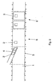
- FIG. 1 a carrier strip (1) mounted on rotatable rollers (5) is transported from left to right.
- a donor head (4) brings electromagnetic security elements (2) of any kind on the carrier tape (1), wherein on the basis of - four labels (3) corresponding - sections (6, 6 ') can be seen that the sequence of security elements ( 2) after the transport path of the carrier tape (1) for four labels (3) by a corresponding control of the drive of the dispensing head (4) repeated: in each case the second label (3) is not provided with a securing element (2).
- the securing elements (2) positioned on the carrier tape (1) are already provided with labels (3) by means of a second dispensing head (not shown).
- FIG. 2 in contrast to FIG. 1, no fixed sequence of the securing elements (2) can be recognized; While only one label (3) is secured in the first left-hand section (6), the two labels (3) shown in the right-hand section (6 ') are provided with securing elements (2).
- Figure 3 illustrates the manufacture of a carrier tape strip, the labels are provided in part with security elements (2) and in part with dummies (7). While the securing elements are applied to the carrier tape (1) by means of the dispensing head (4) shown on the left, a second dispensing head (4 ') is used to apply the dummies (7) in the form and color to the securing elements.
- the illustrated device can on the one hand serve to apply securing elements (2) for laterally juxtaposed labels (3) on the carrier tape (1), on the other hand over the entire width of the carrier tape (1) extending labels (3) with securing elements (2) varying To provide positions.
- individual labels (3) can remain free of securing elements (2). It is also possible, the dispensing heads (4, 4 ') to vary the position of the securing elements (2) in the lateral direction to pivot. Finally, the position of the securing elements (2) in the direction of movement of the carrier tape (1) can be varied by suitable control of the time of application.
- the carrier tape (1) in FIG. 5 is equipped with securing elements (2) by means of a single dispensing head (8).
- the dispensing head (8) has three side by side arranged dispensing channels and is thus suitable to provide three juxtaposed labels (3) with securing elements (2), in each case only a portion of juxtaposed labels (3) can receive security elements, if the dispensing channels can be activated separately from each other.
- a label (3) can be provided with a securing element (2) at three different positions.
- a dispensing head (8) is used to separate securing elements (2) glued on a securing element carrier band from the latter and to donate them to a cover layer (9) already punched into the final shape of a label (3).
- the cover layer (9) is initially adhered to a cover layer carrier tape (10) and is released at a donor edge (11) thereof.
- the securing elements (2) are now applied successively to the exposed covering layer (9) by means of the dispensing head (8).
- the fuse element carrier tape with the securing elements (2) is not moved continuously, but gradually.
- a securing element (2) is separated in a manner known per se from its securing element carrier band at a donor edge (not shown) and forms an adhesive bond with the covering layer (9).
- the now finished security label is finally applied to the carrier tape (1). It is obvious that the position of the securing element (2) on the finished security label is determined by the time at which the securing element (2) is separated from its securing element carrier band and thus can be controlled as desired.
- a cover layer (9 ') of greater length than in FIG. 6 is processed.
- This cover layer (9 ') is, for example, a laminate which is subsequently to be punched into the final shape; therefore, it is provided with a plurality of fuse elements (2).
- the cover layer (9) which may be both a stamped and a non-stamped laminate, is moved at approximately constant speed and separated from the cover layer carrier strip (10) at the donor edge (11) and onto the carrier strip (1 ) applied.
- the securing elements (2) are applied to the carrier strip (1) by means of the dispensing head (8), which moves at the same speed as the covering layer (9). Only then is the cover layer (9) laminated thereon.
- the invention makes it possible to attach the securing elements anywhere on the labels or tags. Another advantage is that the method according to the invention can be used for any types of labels and tags. As a result, you get so a security label strip, which is characterized by value for money and high theft security.
Landscapes
- Physics & Mathematics (AREA)
- Engineering & Computer Science (AREA)
- General Physics & Mathematics (AREA)
- Automation & Control Theory (AREA)
- Computer Security & Cryptography (AREA)
- Electromagnetism (AREA)
- Manufacturing & Machinery (AREA)
- Theoretical Computer Science (AREA)
- Burglar Alarm Systems (AREA)
- Making Paper Articles (AREA)
Description
Die Erfindung bezieht sich auf ein Verfahren der im Oberbegriff des Patentanspruchs 1 angegebenen Art.The invention relates to a method specified in the preamble of
Im Stande der Technik werden hochwertige Artikel in Verkaufseinrichtungen in der Weise gegen Diebstähle geschützt, daß im Bereich des Ausganges des Verkaufsraumes ein Detektor aufgestellt wird, der mit einem in Etiketten oder Anhängern untergebrachten, an den Verkaufsgegenständen befestigten Sicherungselement in Wechselwirkung tritt. Letzteres interagiert beim Unterschreiten eines Schwellenabstandes elektromagnetisch, d. h. durch hochfrequente Wellen, oder magnetisch mit dem Detektor. Falls somit ein - nicht zuvor durch das Verkaufspersonal deaktiviertes - Sicherungselement in der Absicht, es zu stehlen, am Detektor vorbeigeführt wird, spricht der Detektor an und gibt ein akustisches und/oder optisches und/oder elektronisches Warnsignal ab.In the prior art, high-quality articles in shops are protected against theft in such a way that a detector is placed in the area of the outlet of the shop, which interacts with a securing element accommodated in labels or tags attached to the objects of sale. The latter interacts electromagnetically when falling below a threshold distance, d. H. by high-frequency waves, or magnetically with the detector. Thus, if a security element not previously disabled by the sales force, with the intention of stealing it, is passed past the detector, the detector responds and issues an audible and / or visual and / or electronic warning signal.
Die Etiketten werden herkömmlicherweise auf Trägerbändern geliefert, auf denen sie mittels einer Klebeverbindung befestigt sind. Das Verkaufspersonal entferntsie bei der Kennzeichnung der Artikel manuell oder mittels eines geeigneten Handetikettiergerätes vom Trägerband und fixiert sie mittels der auf ihrer Rückseite verbleibenden, adhäsiven Beschichtung an dem jeweiligen Gegenstand. Alternativ können die Gegenstände bereits beim Hersteller oder in Verteilerzentren mit Sicherheitsetiketten versehen werden. Um alle gekennzeichneten Artikel gegen Diebstahl zu sichern, sind sämtliche auf einem Trägerbandstreifen oder einer -rolle gelieferten Etiketten mit - stets an derselben Stelle angebrachten - Sicherungselementen ausgestattet.The labels are conventionally supplied on carrier tapes on which they are attached by means of an adhesive bond. The salesperson removes from the carrier tape manually or by means of a suitable hand-held labeling device when marking the articles and fixes them to the respective article by means of the adhesive coating remaining on their backside. Alternatively, the articles can already be provided with security labels at the manufacturer or in distribution centers. In order to secure all marked articles against theft, all labels supplied on a carrier tape strip or a roll are equipped with securing elements which are always mounted in the same place.
Als nachteilig ist der nicht unerhebliche Preis der Sicherheitsetiketten anzusehen, der primär durch die darin integrierten elektromagnetischen Sicherungselemente bedingt ist. Durch eingehende Untersuchungen wurde belegt, daß die höchste finanzielle Effizienz erreicht wird, falls nur ein gewisser Anteil der von Diebstahl bedrohten Artikel gesichert wird.A disadvantage is the not inconsiderable price of the security labels, which is primarily due to the integrated therein electromagnetic security elements. In-depth research has shown that the highest financial efficiency is achieved if only a certain proportion of articles threatened by theft is secured.
Der Kerngedanke besteht darin, nicht die Gesamtheit (d. h. jedes) der auf einem Streifen gelieferten Etiketten bzw. Anhänger, sondern nur einen festgelegten Anteil ihrer Anzahl (z. B. etwa 80 %) mit Sicherungselementen auszustatten, während die übrigen Etiketten nicht elektromagnetisch aktiv oder aktivierbar sind. Da sämtliche Etiketten bzw. Anhänger aus demselben Material bestehen, gleichartig bedruckt sind und von demselben Streifen stammen, ist nur schwer erkennbar, welches von ihnen elektromagnetisch gesichert und welches ungesichert ist. Als zweckmäßig erweist sich dabei, das Etikett so zu gestalten, daß das Sicherungselement getarnt, d. h. optisch nicht vom übrigen Etikett unterscheidbar ist.The core idea is to provide not all (ie each) of the tags or tags supplied on a strip, but only a fixed proportion of their number (eg, about 80%) with fuse elements, while the other labels are not electromagnetically active or can be activated. Since all labels or tags are made of the same material, are printed the same way and come from the same strip, it is difficult to see which of them electromagnetically secured and which is unsecured. It proves to be useful to make the label so that the fuse element camouflaged, d. H. optically indistinguishable from the rest of the label.
Bezüglich der Art der Sicherungselemente bestehen verschiedene Möglichkeiten:Regarding the type of fuse elements there are different possibilities:
Zunächst kann ein schmaler Streifen aus weichmagnetischem Material zum Einsatz kommen. Er wird in der Ausgangskontrolle mit einem magnetischen Wechselfeld beaufschlagt und entsprechend der jeweiligen Frequenz ummagnetisiert. Da der Streifen nunmehr selbst ein Wechselfeld abstrahlt, das von einer Empfängerantenne detektiert wird, erfolgt eine Aktivierung des Diebstahlalarmes. Zur Deaktivierung kann der Streifen zusätzlich mit im Abstand voneinander angeordneten, hartmagnetischen Metallstücken überdeckt werden.First, a narrow strip of soft magnetic material can be used. It is acted upon in the output control with an alternating magnetic field and re-magnetized according to the respective frequency. Since the strip now emits an alternating field itself, which is detected by a receiver antenna, an activation of the theft alarm takes place. For deactivation, the strip can additionally be covered with spaced, hard-magnetic metal pieces.
Weiterhin ist eine weichmagnetische, auf einer Trägerfolie aufgebrachte, d. h. aufgedampfte oder aufgesputterte Dünnfilmschicht als Sicherungselement vorgeschlagen. Zum Deaktivieren kann darunter und/oder darüber eine hartmagnetische Metallfolie, beispielsweise aus Nickel vorgesehen werden.Furthermore, a soft magnetic, applied to a carrier film, d. H. vapor-deposited or sputtered thin film layer proposed as a fuse element. To deactivate, underneath and / or above, a hard magnetic metal foil, for example of nickel, may be provided.
Aus dem Dokument EP-A-0 578 992 ist ein Verfahren bekannt zur Herstellung von qualitativ hochwertigen Sicherheitsetiketten. Es wird zunächst auf ein nichtmetallisches Band ein hartmagnetischer Metallstreifen und danach auf den Metallstreifen eine Trägerfolie aufgeklebt die eine derartige Dicke und Elastizität aufweist, daß ein Stanzmesser am Ort dessen Einwirkens auf den Metallstreifen eine elastische Deformation des Metallstreifens \ und der Trägerfolie verursacht, die ausreicht, um den Metallstreifen zu trennen.From the document EP-A-0 578 992 a method is known for the production of high quality security labels. It is first adhered to a non-metallic tape a hard magnetic metal strip and then on the metal strip, a support film having such a thickness and elasticity that a punching knife at the location of its action on the metal strip causes elastic deformation of the metal strip \ and the carrier film, which is sufficient to separate the metal strip.
Aus dem nichtmetallischen Band und dem Metallstreifen werden Teile herausstanzt, die von der Trägerfolie abgelöst werden. Auf die verbleibenden Teile des hartmagnetischen Metallstreifens wird ein weichmagnelisches Metallband aufgebracht. Im Anschluß daran wird auf die eine Seite des auf obige Weise hergestellten Schichtmaterials Etikettenpapier und auf die andere Seite ein Trägerband aufgeklebt, so daß sich ein Zwischenprodukt ergibt, aus dem Etiketten gestanzt werden können. Schließlich sind alternativ zu den magnetischen Sicherungseinrichtungen elektromagnetisch arbeitende Resonanzschwingkreise einsetzbar, die als Dünnschichtschaltungen realisiert werden können. Am Ausgang werden die aus einem Kondensator und einer Induktivität bestehenden Schwingkreise mit einem elektromagnetischen Hochfrequenzfeld beaufschlagt, so daß sie im Resonanzfall ebenfalls Wellen abstrahlen, die zur Alarmierung mittels geeigneter Antennen erfaßt werden.From the non-metallic band and the metal strip parts are punched out, which are detached from the carrier film. On the remaining parts of the hard magnetic metal strip a weichmagnelisches metal strip is applied. Subsequently, label paper is adhered to one side of the sheet material prepared in the above manner and a carrier tape is adhered to the other side to give an intermediate product from which labels can be punched. Finally, as an alternative to the magnetic safety devices, electromagnetically operating resonant circuits can be used, which can be realized as thin-film circuits. At the output of a capacitor and an inductance existing oscillating circuits are subjected to a high-frequency electromagnetic field, so that they also emit waves in the case of resonance, which are detected for alarming by means of suitable antennas.
Aufgabe der Erfindung ist es, ein wirtschaftliches Verfahren zur Herstellung eines Sicherheitsetikettenstreifens anzugeben.The object of the invention is to provide an economical method for producing a security label strip.
Diese Aufgabe wird erfindungsgemäß durch ein Verfahren der eingangs genannten Art gelöst, das die im kennzeichnenden Teil des Anspruchs 1 angegebenen Schritte umfaßt. Vorteilhafte Ausgestaltungen der Erfindung bilden die Gegenstände der abhängigen Ansprüche.This object is achieved by a method of the type mentioned, comprising the steps indicated in the characterizing part of
Die Grundidee besteht bei dem erfindungsgemäßen Verfahren darin, die Sicherungselemente von einem Sicherungselementeträgerband abzulösen und derart zu spenden, daß sie in eine gewünschte Position auf einem Sicherheitsetikett oder -anhänger gelangen. Die Sicherungselemente, die eine beliebige Form und Größe aufweisen können, werden somit zunächst durch eine Klebeverbindung auf einem Sicherungselementeträgerband befestigt und bei der Herstellung der Sicherheitsetiketten sukzessive an einer Spendkante wiederum davon abgelöst. Das dabei freiwerdende Sicherungselement wird nunmehr mit den übrigen Teilen des Etiketts oder Anhängers zusammengeführt und -laminiert. Entscheidend ist dabei, daß die Position des Sicherungselementes auf dem (daran vorbeigeführten) Etikett bzw. Anhänger durch den Zeitpunkt des Spendvorganges festgelegt wird und somit beliebig steuerbar wird. Insbesondere besteht die Möglichkeit, große Etiketten oder Anhänger mit wesentlich kleineren Sicherungselementen zu versehen.The basic idea in the method according to the invention is to detach the securing elements from a securing element carrier band and to donate such that they are in a desired position Get on a security tag or tag. The securing elements, which may have any shape and size, are thus first secured by an adhesive bond on a fuse element carrier tape and successively detached in the manufacture of security labels on a donation edge thereof. The case released securing element is now merged with the other parts of the label or trailer and laminated. It is crucial that the position of the fuse element on the (past it) label or trailer is determined by the time of the dispensing process and thus is arbitrarily controlled. In particular, it is possible to provide large labels or tags with much smaller security elements.
Die Vorteile bestehen vornehmlich darin, daß die Produktionskosten der Sicherheitsetiketten oder Sicherungsanhänger durch eine Verminderung der Flächen der Sicherungselemente reduzierbar sind, da beliebig kleine Sicherungselemente Verwendung finden können. Außerdem wird es möglich, ein standardisiertes Sicherungselement auf Etiketten und Anhänger beliebiger Art und Größe aufzubringen, was eine entscheidende Reduzierung der Lagerkosten zur Folge hat, da nur noch eine Art von Sicherungselementen vorrätig zu halten ist. Offensichtlich ist das vorgeschlagene Verfahren auch dazu geeignet, sämtliche Etiketten bzw. Anhänger eines Streifens mit Sicherungselementen auszustatten.The advantages consist primarily in the fact that the production costs of the security labels or security tags can be reduced by reducing the areas of the security elements, since any small security elements can be used. It also makes it possible to apply a standardized security element on labels and tags of any type and size, which has a significant reduction in storage costs result, since only one type of security elements is to keep in stock. Obviously, the proposed method is also suitable for providing all labels or tags of a strip with securing elements.
Zur sicheren Verbindung mit den Sicherheitsetiketten - bzw. mit den mit ihnen beklebten Gegenständen - oder den Anhängern ist vorgeschlagen, die Sicherungselemente derart auf das Sicherungselementeträgerband aufzukleben, daß ihre dem Trägerband zugewandte Seite auch nach dem Spendvorgang, d. h. nach dem Ablösen vom Sicherungselementeträgerband, adhäsiv bleibt. Die zum Fixieren des Sicherungselementes auf dem Sicherungselementeträgerband dienende Klebstoffschicht kann somit auch nach dem Spendvorgang zu seiner Befestigung dienen.For secure connection with the security labels - or with the articles stuck to them - or the trailers is proposed to glue the fuse elements on the fuse element carrier tape so that their side facing the carrier tape after the dispensing operation, d. H. after detachment from the fuse element carrier tape, remains adhesive. The serving for fixing the fuse element on the fuse element carrier tape adhesive layer can thus also serve after the dispensing to its attachment.
Es bestehen bezüglich des Laminierens verschiedene Möglichkeiten. In einer vorteilhaften Ausführungsform werden die Sicherungselemente auf eine mit einer selbstklebenden Beschichtung versehene Fläche der Deckschicht aufgebracht; die Fixierung der Sicherungselemente erfolgt somit durch die auf der Deckschicht bereits vorhandene Klebstoffschicht. Um ein Sicherheitsetikett auf einer möglichst großen Fläche mit einem Gegenstand verkleben zu können, wird in diesem Fall die adhäsive Beschichtung der Sicherungselemente - die zu ihrer Anbringung auf dem Sicherungselementeträgerband dient - derart positioniert, daß sie der selbstklebenden Beschichtung der Deckschicht gegenüberliegt.There are various possibilities with regard to lamination. In an advantageous embodiment, the securing elements are applied to a provided with a self-adhesive coating surface of the cover layer; The fixing of the securing elements is thus effected by the adhesive layer already present on the cover layer. In order to be able to glue a security label on an area as large as possible with an object, in this case the adhesive coating of the securing elements-which serves for their attachment to the securing element carrier tape-is positioned such that it faces the self-adhesive coating of the cover layer.
Im speziellen findet dabei eine Deckschicht Verwendung, deren selbstklebende Fläche auf einem beliebigen Trägerband befestigt ist, das im folgenden als Deckschicht-Trägerband bezeichnet wird. Letzteres wird von der Deckschicht abgezogen, so daß die selbstklebende Fläche freiliegt, und die Sicherungselemente werden darauf gespendet. Anschließend wird die nunmehr mit Sicherungselementen ausgestattete Deckschicht auf das Trägerband aufgebracht. Die Deckschicht und das Trägerband nehmen die Sicherungselemente nach Art eines Sandwichs zwischen sich auf.In particular, a cover layer is used, the self-adhesive surface of which is fastened on an arbitrary carrier tape, which is referred to below as a cover-layer carrier tape. The latter is peeled off the cover layer so that the self-adhesive surface is exposed, and the securing elements are dispensed thereon. Subsequently, the now equipped with security elements cover layer is applied to the carrier tape. The cover layer and the carrier tape sandwich the securing elements in the manner of a sandwich.
Alternativ zur Spendung der Sicherungselemente auf die Deckschicht können sie auf das Trägerband aufgeklebt werden, auf das anschließend die Deckschicht aufgebracht wird. Die Befestigung der Sicherungselemente an dem Trägerband erfolgt vorzugsweise mit derselben adhäsiven Beschichtung, mit der das Sicherungselement vor dem Spendvorgang am Sicherungselementeträgerband befestigt war. Im Regelfall ist auch die mit dem Trägerband in Kontakt tretende Fläche der Deckschicht mit einer selbstklebenden Beschichtung versehen.As an alternative to the delivery of the securing elements to the cover layer, they can be adhesively bonded to the carrier tape onto which the cover layer is subsequently applied. The attachment of the securing elements on the carrier tape is preferably carried out with the same adhesive coating with which the securing element was attached to the fuse element carrier tape before the dispensing operation. As a rule, the surface of the cover layer which comes into contact with the carrier tape is also provided with a self-adhesive coating.
Dabei bietet es sich an, eine Deckschicht zu verwenden, die mit einer selbstklebenden Fläche auf einem Deckschicht-Trägerband befestigt ist. Letzteres wird von der Deckschicht abgezogen, bevor diese auf das Trägerband mit den Sicherungselementen aufgeklebt wird.It is advisable to use a cover layer which is fastened with a self-adhesive surface on a cover layer carrier tape. The latter is removed from the cover layer before it is glued to the carrier tape with the securing elements.
Weiterhin ist es möglich, die Deckschicht in bereits ausgestanzter Form mit den Sicherungselementen zusammenzuführen. Auch die Alternative, die Deckschicht erst nach dem Zusammenlaminieren mit den Sicherungselementen in ihre endgültige Etiketten- und Anhängerform auszustanzen, ist denkbar.Furthermore, it is possible to combine the cover layer in already punched-out form with the securing elements. The alternative of punching the cover layer into its final label and trailer form only after being laminated together with the securing elements is also conceivable.
Als Material der Deckschicht kommen primär Papier, Pappe und Kunststoff in Frage. Besteht die Deckschicht aus bedruckbarem Etikettenpapier und das Trägerband aus mit Silikon beschichtetem Papier, sind Sicherheitsetiketten herstellbar, die in herkömmlichen Handetikettiergeräten verwendet werden können. Aus Pappe oder Kunststoff können insbesondere strapazierfähige Sicherheitsanhänger hergestellt werden, wie sie beispielsweise zum Etikettieren von Textilien Verwendung finden.The material of the cover layer are primarily paper, cardboard and plastic in question. If the top layer consists of printable label paper and the carrier tape is made of silicone-coated paper, security labels can be produced which can be used in conventional hand-held labeling machines. Made of cardboard or plastic especially durable security tags can be made, as they are used, for example, for labeling textiles.
Im folgenden werden Ausführungsformen der Erfindung anhand der Zeichnung näher erläutert. Sie zeigen in schematischer Darstellung in
- Figur 1: die Herstellung von Trägerbandstreifen mit regelmäßig angeordneten Sicherungselementen,
- Figur 2: die Herstellung von Trägerbandstreifen mit zufällig angeordneten Sicherungselementen,
- Figur 3: die Herstellung von Trägerbandstreifen mit Attrappen von Sicherungselementen,
- Figur 4: die Herstellung von Trägerbandstreifen mit unterschiedlich positionierten Sicherungselementen mit mehreren Spendköpfen,
- Figur 5: die Herstellung von Trägerbandstreifen mit unterschiedlich positionierten Sicherungselementen mit einem Spendkopf,
- Figur 6: die Herstellung von Trägerbandstreifen unter Verwendung gestanzter Etiketten.
- Figur 7: die Herstellung von Trägerbandstreifen unter Verwendung nicht gestanzter Etiketten,
- Figur 8: die Herstellung von Trägerbandstreifen, wobei die Sicherungselemente auf ein Trägerband gespendet werden.
- FIG. 1 shows the production of carrier tape strips with regularly arranged securing elements,
- FIG. 2 shows the production of carrier tape strips with randomly arranged securing elements,
- FIG. 3 shows the production of carrier tape strips with dummies of security elements,
- FIG. 4 shows the production of carrier tape strips with differently positioned securing elements with a plurality of dispensing heads;
- FIG. 5 shows the production of carrier tape strips with differently positioned securing elements with a dispensing head,
- Figure 6: the production of carrier tape strips using stamped labels.
- FIG. 7: the production of carrier tape strips using non-stamped labels,
- Figure 8: the production of carrier tape strips, wherein the securing elements are donated to a carrier tape.
In Figur wird ein auf drehbaren Rollen (5) gelagertes Trägerband (1) von links nach rechts transportiert. Ein Spendkopf (4) bringt elektromagnetische Sicherungselemente (2) beliebiger Art auf das Trägerband (1) auf, wobei anhand der - jeweils vier Etiketten (3) entsprechenden - Abschnitte (6, 6') erkennbar ist, daß sich die Reihenfolge der Sicherungselemente (2) nach dem Transportweg des Trägerbandes (1) für vier Etiketten (3) durch eine entsprechende Steuerung des Antriebs des Spendkopfes (4) wiederholt: jeweils das zweite Etikett (3) wird nicht mit einem Sicherungselement (2) versehen. Im rechts eingezeichneten Abschnitt (6') sind die auf dem Trägerband (1) positionierten Sicherungselemente (2) mittels eines nicht eingezeichneten, zweiten Spendkopfes bereits mit Etiketten (3) versehen.In FIG. 1, a carrier strip (1) mounted on rotatable rollers (5) is transported from left to right. A donor head (4) brings electromagnetic security elements (2) of any kind on the carrier tape (1), wherein on the basis of - four labels (3) corresponding - sections (6, 6 ') can be seen that the sequence of security elements ( 2) after the transport path of the carrier tape (1) for four labels (3) by a corresponding control of the drive of the dispensing head (4) repeated: in each case the second label (3) is not provided with a securing element (2). In the section (6 ') shown on the right, the securing elements (2) positioned on the carrier tape (1) are already provided with labels (3) by means of a second dispensing head (not shown).
In Figur 2 ist im Unterschied zur Figur 1 keine festgelegte Reihenfolge der Sicherungselemente (2) erkennbar; während im ersten, links eingezeichneten Abschnitt (6) nur ein Etikett (3) gesichert wird, sind die beiden im rechten Abschnitt (6') dargestellten Etiketten (3) mit Sicherungselementen (2) ausgestattet.In FIG. 2, in contrast to FIG. 1, no fixed sequence of the securing elements (2) can be recognized; While only one label (3) is secured in the first left-hand section (6), the two labels (3) shown in the right-hand section (6 ') are provided with securing elements (2).
Figur 3 stellt die Herstellung eines Trägerbandstreifens dar, dessen Etiketten zum Teil mit Sicherungselementen (2) und zum Teil mit Attrappen (7) versehen sind. Während die Sicherungselemente mittels des links eingezeichneten Spendkopfes (4) auf das Trägerband (1) aufgetragen werden, dient ein zweiter Spendkopf (4') zum Aufbringen der in Form und Farbgebung mit den Sicherungselementen übereinstimmenden Attrappen (7).Figure 3 illustrates the manufacture of a carrier tape strip, the labels are provided in part with security elements (2) and in part with dummies (7). While the securing elements are applied to the carrier tape (1) by means of the dispensing head (4) shown on the left, a second dispensing head (4 ') is used to apply the dummies (7) in the form and color to the securing elements.
In Figur 4 wird das Trägerband (1) aus zwei unterschiedlichen, seitlich (d. h. in der Ebene der Etiketten (3), orthogonal zur Transportrichtung) und in der Vorschubrichtung des Trägerbandes (1) versetzten Spendköpfen (4, 4') mit Sicherungselementen (2) versehen. Anhand der Abschnitte (6, 6') ist erkennbar, daß einige Positionen frei bleiben, so daß im Ergebnis nicht alle Etiketten (3) mit Sicherungselementen (2) versehen werden. Außerdem variiert die Reihenfolge der Sicherungselemente (2) nach dem Zufallsprinzip. Die dargestellte Vorrichtung kann einerseits dazu dienen, Sicherungselemente (2) für seitlich nebeneinander angeordnete Etiketten (3) auf das Trägerband (1) aufzubringen, andererseits sich über die gesamte Breite des Trägerbandes (1) erstreckende Etiketten (3) mit Sicherungselementen (2) variierender Positionen zu versehen. In beiden Fällen können einzelne Etiketten (3) frei von Sicherungselementen (2) bleiben. Es besteht auch die Möglichkeit, die Spendköpfe (4, 4') zur Variation der Lage der Sicherungselemente (2) in seitlicher Richtung zu verschwenken. Schließlich kann die Position der Sicherungselemente (2) in der Bewegungsrichtung des Trägerbandes (1) durch eine geeignete Steuerung des Zeitpunktes des Aufbringens variiert werden.In Figure 4, the carrier tape (1) of two different, laterally (ie in the plane of the labels (3), orthogonal to the transport direction) and in the feed direction of the carrier tape (1) offset dispensing heads (4, 4 ') with securing elements (2 ) Mistake. It can be seen from the sections (6, 6 ') that some positions remain free, so that as a result not all the labels (3) are provided with securing elements (2). In addition, the order of the fuse elements (2) varies at random. The illustrated device can on the one hand serve to apply securing elements (2) for laterally juxtaposed labels (3) on the carrier tape (1), on the other hand over the entire width of the carrier tape (1) extending labels (3) with securing elements (2) varying To provide positions. In both cases, individual labels (3) can remain free of securing elements (2). It is also possible, the dispensing heads (4, 4 ') to vary the position of the securing elements (2) in the lateral direction to pivot. Finally, the position of the securing elements (2) in the direction of movement of the carrier tape (1) can be varied by suitable control of the time of application.
Im Unterschied zu Figur 4 wird das Trägerband (1) in Figur 5 mittels eines einzigen Spendkopfes (8) mit Sicherungselementen (2) ausgestattet. Der Spendkopf (8) weist jedoch drei seitlich nebeneinander angeordnete Spendkanäle auf und ist somit geeignet, drei nebeneinander angeordnete Etiketten (3) mit Sicherungselementen (2) zu versehen, wobei jeweils nur ein Teil der nebeneinander angeordneten Etiketten (3) Sicherungselemente erhalten kann, falls die Spendkanäle getrennt voneinander aktivierbar sind. Alternativ kann ein Etikett (3) an drei unterschiedlichen Positionen mit einem Sicherungselement (2) ausgestattet werden.In contrast to FIG. 4, the carrier tape (1) in FIG. 5 is equipped with securing elements (2) by means of a single dispensing head (8). However, the dispensing head (8) has three side by side arranged dispensing channels and is thus suitable to provide three juxtaposed labels (3) with securing elements (2), in each case only a portion of juxtaposed labels (3) can receive security elements, if the dispensing channels can be activated separately from each other. Alternatively, a label (3) can be provided with a securing element (2) at three different positions.
In Figur 6 findet ein Spendkopf (8) Verwendung, um auf einem Sicherungselementeträgerband aufgeklebte Sicherungselemente (2) von letzterem zu trennen und auf eine bereits in die endgültige Form eines Etiketts (3) ausgestanzte Deckschicht (9) zu spenden. Die Deckschicht (9) ist anfangs auf einem Deckschicht-Trägerband (10) aufgeklebt und wird an einer Spendkante (11) davon gelöst. In der Regel ist die Geschwindigkeit, mit der die Deckschicht (9) am Spendkopf (8) vorbeigeführt wird, konstant? Auf die freiliegende Deckschicht (9) werden nunmehr sukzessive die Sicherungselemente (2) mittels des Spendkopfes (8) aufgebracht. Das Sicherungselementeträgerband mit den Sicherungselementen (2) wird nicht kontinuierlich, sondern schrittweise bewegt. Bei jedem Schritt wird ein Sicherungselement (2) in an sich bekannter Weise an einer (nicht eingezeichneten) Spendkante von seinem Sicherungselementeträgerband getrennt und geht eine adhäsive Bindung mit der Deckschicht (9) ein. Das nunmehr fertige Sicherheitsetikett wird schließlich auf das Trägerband (1) aufgebracht. Es ist offensichtlich, daß die Position des Sicherungselementes (2) auf dem fertigen Sicherheitsetikett durch den Zeitpunkt festgelegt wird, an dem das Sicherungselement (2) von seinem Sicherungselementeträgerband getrennt wird und somit beliebig steuerbar ist.In FIG. 6, a dispensing head (8) is used to separate securing elements (2) glued on a securing element carrier band from the latter and to donate them to a cover layer (9) already punched into the final shape of a label (3). The cover layer (9) is initially adhered to a cover layer carrier tape (10) and is released at a donor edge (11) thereof. As a rule, the speed with which the cover layer (9) passes by the dispensing head (8) is constant? The securing elements (2) are now applied successively to the exposed covering layer (9) by means of the dispensing head (8). The fuse element carrier tape with the securing elements (2) is not moved continuously, but gradually. At each step, a securing element (2) is separated in a manner known per se from its securing element carrier band at a donor edge (not shown) and forms an adhesive bond with the covering layer (9). The now finished security label is finally applied to the carrier tape (1). It is obvious that the position of the securing element (2) on the finished security label is determined by the time at which the securing element (2) is separated from its securing element carrier band and thus can be controlled as desired.
In Figur 7 wird eine Deckschicht (9') mit größerer Länge als in Figur 6 verarbeitet. Diese Deckschicht (9') ist beispielsweise ein Laminat, das anschließend noch in die endgültige Form zu stanzen ist; daher wird es mit mehreren Sicherungselementen (2) versehen.In FIG. 7, a cover layer (9 ') of greater length than in FIG. 6 is processed. This cover layer (9 ') is, for example, a laminate which is subsequently to be punched into the final shape; therefore, it is provided with a plurality of fuse elements (2).
In Figur 8 wird die Deckschicht (9), die sowohl ein gestanztes als auch ein noch nicht gestanztes Laminat sein kann, mit etwa konstanter Geschwindigkeit bewegt und an der Spendkante (11) vom Deckschicht-Trägerband (10) getrennt und auf das Trägerband (1) aufgebracht. Die Sicherungselemente (2) werden im Unterschied zu den vorhergehenden Figuren 6 und 7 jedoch mittels des Spendkopfes (8) auf das Trägerband (1) aufgebracht, das sich mit derselben Geschwindigkeit wie die Deckschicht (9) bewegt. Erst im Anschluß daran wird die Deckschicht (9) darauf laminiert. Anzumerken bleibt, daß die Trägerbänder (1, 10) - ohne die bzw. mit der Deckschicht (9) - von Rollen abgewickelt und auf andere Rollen aufgewickelt werden.In FIG. 8, the cover layer (9), which may be both a stamped and a non-stamped laminate, is moved at approximately constant speed and separated from the cover layer carrier strip (10) at the donor edge (11) and onto the carrier strip (1 ) applied. However, in contrast to the preceding Figures 6 and 7, the securing elements (2) are applied to the carrier strip (1) by means of the dispensing head (8), which moves at the same speed as the covering layer (9). Only then is the cover layer (9) laminated thereon. It should be noted that the carrier tapes (1, 10) - without the or with the cover layer (9) - unwound from rolls and wound on other roles.
Es ist offensichtlich, daß die Erfindung ermöglicht, die Sicherungselemente an beliebiger Stelle der Etiketten oder Anhänger anzubringen. Ein weiterer Vorzug besteht darin, daß das erfindungsgemäße Verfahren bei beliebigen Arten von Etiketten und Anhängern zur Verwendung kommen kann. Im Ergebnis erhältman also einen Sicherheitsetikettenstreifen, der sich durch Preiswürdigkeit und hohe Diebstahlsicherheit auszeichnet. It is obvious that the invention makes it possible to attach the securing elements anywhere on the labels or tags. Another advantage is that the method according to the invention can be used for any types of labels and tags. As a result, you get so a security label strip, which is characterized by value for money and high theft security.
Claims (6)
- A method of manufacturing a security label strip in which an overlayer (9) and electromagnetically active or activatable security elements (2) are joined together,
characterized by the steps of
individually adhesive-bonding the security elements (2) to a security element carrier web, and
successively detaching the security elements (2) from the security element carrier web at a dispensing edge and laminating them together with the overlayer (9) and a carrier web (1), which receive the security elements (2) between them in the manner of a sandwich. - The method as claimed in claim 1,
characterized by the step of adhesive-bonding the security elements (2) to the security element carrier web in such manner that they remain adhesive upon detachment therefrom. - The method as claimed in claim 1 or 2,
characterized by the step of applying the security elements (2) to an area of the overlayer (9) provided with a self-adhesive coating. - The method as claimed in claim 3,
characterized by the steps of
affixing the overlayer (9) with the self-adhesive area to an overlayer carrier web (10), detaching the overlayer carrier web (10) from the overlayer (9),
applying the security elements (2) to the self-adhesive area of the overlayer (9), and
applying the overlayer (9) with the security elements (2) to the carrier web (1) and laminating the two together. - The method as claimed in claim 1 or 2,
characterized by the steps of adhesive-bonding the security elements (2) to the carrier web (1) and applying the overlayer (9) to the carrier web (1) carrying the security elements (2). - The method as claimed in claim 5,
characterized by the step of affixing the overlayer (9) with a self-adhesive area thereof to an overlayer carrier web (10) and detaching the overlayer carrier web (10) from the overlayer (9) before the overlayer (9) is adhesive-bonded to the carrier web (1) carrying the security elements (1).
Applications Claiming Priority (5)
| Application Number | Priority Date | Filing Date | Title |
|---|---|---|---|
| DE4416444A DE4416444C2 (en) | 1994-05-10 | 1994-05-10 | Security label strip |
| DE4416444 | 1994-05-10 | ||
| DE4436284A DE4436284C2 (en) | 1994-10-11 | 1994-10-11 | Process for the production of security labels or security tags |
| DE4436284 | 1994-10-11 | ||
| EP95102132A EP0682333B1 (en) | 1994-05-10 | 1995-02-16 | Label stock |
Related Parent Applications (1)
| Application Number | Title | Priority Date | Filing Date |
|---|---|---|---|
| EP95102132A Division EP0682333B1 (en) | 1994-05-10 | 1995-02-16 | Label stock |
Publications (4)
| Publication Number | Publication Date |
|---|---|
| EP0899705A2 EP0899705A2 (en) | 1999-03-03 |
| EP0899705A3 EP0899705A3 (en) | 1999-08-11 |
| EP0899705B1 EP0899705B1 (en) | 2002-09-04 |
| EP0899705B2 true EP0899705B2 (en) | 2006-03-22 |
Family
ID=25936474
Family Applications (2)
| Application Number | Title | Priority Date | Filing Date |
|---|---|---|---|
| EP95102132A Expired - Lifetime EP0682333B1 (en) | 1994-05-10 | 1995-02-16 | Label stock |
| EP98119673A Expired - Lifetime EP0899705B2 (en) | 1994-05-10 | 1995-02-16 | Method of producing a sheet of security tags |
Family Applications Before (1)
| Application Number | Title | Priority Date | Filing Date |
|---|---|---|---|
| EP95102132A Expired - Lifetime EP0682333B1 (en) | 1994-05-10 | 1995-02-16 | Label stock |
Country Status (4)
| Country | Link |
|---|---|
| US (2) | US5614278A (en) |
| EP (2) | EP0682333B1 (en) |
| BR (1) | BR9501388A (en) |
| DE (2) | DE59510365D1 (en) |
Families Citing this family (63)
| Publication number | Priority date | Publication date | Assignee | Title |
|---|---|---|---|---|
| US6045652A (en) * | 1992-06-17 | 2000-04-04 | Micron Communications, Inc. | Method of manufacturing an enclosed transceiver |
| US7158031B2 (en) | 1992-08-12 | 2007-01-02 | Micron Technology, Inc. | Thin, flexible, RFID label and system for use |
| CA2171526C (en) * | 1995-10-13 | 1997-11-18 | Glen E. Mavity | Combination article security target and printed label and method and apparatus for making and applying same |
| ES2117580B1 (en) * | 1996-10-25 | 1999-02-16 | Customer Service S L | LABELING SYSTEM OR SECURITY MARKING. |
| DE19650611A1 (en) * | 1996-12-06 | 1998-06-10 | Meto International Gmbh | Method and device for the production of security elements for electronic article security as well as a corresponding tape material |
| DE19650610A1 (en) * | 1996-12-06 | 1998-06-10 | Meto International Gmbh | Method and device for producing electronic security elements |
| FR2760682B1 (en) * | 1997-03-17 | 1999-08-27 | Etiqso | DEVICE DESIGNED TO PLACE A SECONDARY ELEMENT ATTACHED TO A SILICONE SUPPORT UNDER A PRIMARY ELEMENT, ITSELF ATTACHED TO A SILICONE SUPPORT |
| DE19711626A1 (en) * | 1997-03-20 | 1998-09-24 | Meto International Gmbh | Strips for providing security elements for electronic article surveillance |
| EP0927412B1 (en) * | 1997-06-14 | 2003-09-17 | Pasquini und Kromer GmbH | Device for producing a strip with self-adhesive labels or other materials with parts placed underneath and a device for laterally guiding edges |
| DE19725276A1 (en) * | 1997-06-14 | 1999-01-14 | Pasquini Und Kromer Gmbh | Arrangement for producing a strip with self-adhesive labels or other materials with parts beneath and for lateral edge guidance |
| US6339385B1 (en) | 1997-08-20 | 2002-01-15 | Micron Technology, Inc. | Electronic communication devices, methods of forming electrical communication devices, and communication methods |
| US6019865A (en) * | 1998-01-21 | 2000-02-01 | Moore U.S.A. Inc. | Method of forming labels containing transponders |
| US5897741A (en) * | 1998-02-09 | 1999-04-27 | Premark Feg L.L.C. | Apparatus for applying security tags to labels |
| JP3084478B2 (en) * | 1998-03-20 | 2000-09-04 | 弘安 大島 | Product with unauthorized detection of product removal and products with measures to prevent unauthorized removal |
| US6357503B1 (en) | 1998-06-13 | 2002-03-19 | Pasquini Und Kromer Gmbh | Device for producing a strip with self-adhesive labels or other materials with parts placed underneath and a device for laterally guiding edges |
| US6724895B1 (en) | 1998-06-18 | 2004-04-20 | Supersensor (Proprietary) Limited | Electronic identification system and method with source authenticity verification |
| DE19827592A1 (en) * | 1998-06-20 | 1999-12-23 | Meto International Gmbh | Device and method for producing labels for electronic article surveillance |
| US20050199344A1 (en) * | 1998-08-04 | 2005-09-15 | Kent Lord | Label feeder |
| DE19850038A1 (en) * | 1998-10-30 | 2000-05-04 | Meto International Gmbh | Device and method for inserting a security and / or identification element between two layers of a marking strip for luggage |
| DE19910480C1 (en) | 1999-03-10 | 2000-09-28 | Skidata Ag | Non-transferable credential |
| US6404341B1 (en) * | 1999-04-06 | 2002-06-11 | 1175634 Ontario Limited | Security tag and method of making the same |
| US6280544B1 (en) * | 1999-04-21 | 2001-08-28 | Intermec Ip Corp. | RF tag application system |
| US6645327B2 (en) | 1999-04-21 | 2003-11-11 | Intermec Ip Corp. | RF tag application system |
| NL1011925C2 (en) * | 1999-04-28 | 2000-11-06 | Nl Speciaal Drukkerijen B V | Method and device for manufacturing a security member. |
| US8585852B2 (en) * | 1999-06-16 | 2013-11-19 | Vanguard Identification Systems, Inc. | Methods of making printed planar radio frequency identification elements |
| US6368447B1 (en) * | 1999-07-26 | 2002-04-09 | Eastman Kodak Company | Method for assembling critically positioned camera component on camera body |
| US6432500B1 (en) * | 1999-08-24 | 2002-08-13 | Pharmaceutic Litho & Label Company, Inc. | Label with booklet |
| US6147662A (en) * | 1999-09-10 | 2000-11-14 | Moore North America, Inc. | Radio frequency identification tags and labels |
| US6943678B2 (en) * | 2000-01-24 | 2005-09-13 | Nextreme, L.L.C. | Thermoformed apparatus having a communications device |
| BE1013273A3 (en) * | 2000-02-08 | 2001-11-06 | Reynders Etiketten Nv | IDENTIFIABLE ARTICLE AND METHOD FOR MANUFACTURING IT, AND METHOD AND DEVICE FOR DETECTING IDENTIFIABLE ARTICLES. |
| CA2399185A1 (en) | 2000-03-01 | 2001-09-07 | Larry Ancahas | Contact programmer |
| DE10019438A1 (en) * | 2000-04-19 | 2001-10-25 | Meto International Gmbh | Security tagging unit has automatic pick up and bonding is economical to do suitable for all tag types |
| US6830795B1 (en) | 2000-08-28 | 2004-12-14 | The Standard Register Company | Stripe coated linerless labels |
| US7017820B1 (en) * | 2001-02-08 | 2006-03-28 | James Brunner | Machine and process for manufacturing a label with a security element |
| US7218527B1 (en) * | 2001-08-17 | 2007-05-15 | Alien Technology Corporation | Apparatuses and methods for forming smart labels |
| US7137000B2 (en) | 2001-08-24 | 2006-11-14 | Zih Corp. | Method and apparatus for article authentication |
| US6786263B1 (en) * | 2001-09-07 | 2004-09-07 | Fox Iv Technologies, Inc. | Apparatus for printing and applying labels |
| US6969134B2 (en) | 2001-10-01 | 2005-11-29 | Zih Corp. | Printer or other media processor with on-demand selective media converter |
| US20030061947A1 (en) * | 2001-10-01 | 2003-04-03 | Hohberger Clive P. | Method and apparatus for associating on demand certain selected media and value-adding elements |
| US6947777B2 (en) * | 2002-10-16 | 2005-09-20 | Ward-Kraft, Inc. | Compact electronic communication device with self-mounting feature and method of removably coupling such a device to a surface |
| GB2395462B (en) * | 2002-11-21 | 2006-04-05 | Hewlett Packard Co | Apparatus for printing and memory tag application and method therefor |
| CA2520978A1 (en) * | 2003-04-08 | 2004-10-21 | Kma Global Solutions Inc. | Dual security label |
| JP2005157661A (en) * | 2003-11-25 | 2005-06-16 | Brother Ind Ltd | Wireless tag creation device and cartridge |
| US20050116034A1 (en) * | 2003-11-28 | 2005-06-02 | Masato Satake | Printing system |
| US7138919B2 (en) * | 2004-02-23 | 2006-11-21 | Checkpoint Systems, Inc. | Identification marking and method for applying the identification marking to an item |
| US7704346B2 (en) * | 2004-02-23 | 2010-04-27 | Checkpoint Systems, Inc. | Method of fabricating a security tag in an integrated surface processing system |
| US8099335B2 (en) * | 2004-02-23 | 2012-01-17 | Checkpoint Systems, Inc. | Method and system for determining billing information in a tag fabrication process |
| US7116227B2 (en) * | 2004-02-23 | 2006-10-03 | Checkpoint Systems, Inc. | Tag having patterned circuit elements and a process for making same |
| US7119685B2 (en) * | 2004-02-23 | 2006-10-10 | Checkpoint Systems, Inc. | Method for aligning capacitor plates in a security tag and a capacitor formed thereby |
| US7384496B2 (en) * | 2004-02-23 | 2008-06-10 | Checkpoint Systems, Inc. | Security tag system for fabricating a tag including an integrated surface processing system |
| EP1638380A1 (en) * | 2004-09-15 | 2006-03-22 | Schreiner Group GmbH & Co. KG | Method of closing casings with foil covers and correspondingly closed casing |
| JP4483647B2 (en) * | 2005-03-24 | 2010-06-16 | 富士ゼロックス株式会社 | Medium provided with magnetic element, medium information reading method and apparatus |
| US20060260754A1 (en) * | 2005-05-23 | 2006-11-23 | Ward/Kraft | System and method for generating intermediate variable pressure sensitive webs |
| US7646304B2 (en) | 2006-04-10 | 2010-01-12 | Checkpoint Systems, Inc. | Transfer tape strap process |
| JP2008021282A (en) * | 2006-06-12 | 2008-01-31 | Brother Ind Ltd | Label body and label body creation device |
| EP1939794A3 (en) | 2006-12-29 | 2009-04-01 | Vanguard Identification Systems, Inc. | Printed planar RFID element wristbands and like personal identification devices |
| JP4849012B2 (en) * | 2007-06-08 | 2011-12-28 | 富士ゼロックス株式会社 | Printing device, detection system, document creation method and program |
| US20100102968A1 (en) * | 2008-06-23 | 2010-04-29 | Tag (Bvi) Ltd. | Electronic article surveillance device and related assembly and method |
| US9401745B1 (en) | 2009-12-11 | 2016-07-26 | Micron Technology, Inc. | Wireless communication link using near field coupling |
| US9221667B2 (en) * | 2012-05-24 | 2015-12-29 | SteadyServ Technologies, LLC | Draft beer supply chain systems and methods |
| CA2929131C (en) * | 2013-11-03 | 2023-11-07 | SteadyServ Technologies, LLC | Draft beer supply chain systems and methods |
| US10086599B2 (en) | 2016-03-16 | 2018-10-02 | Ward Kraft, Inc. | Label peeler system for printers and methods for making and using same |
| US10578475B2 (en) | 2016-04-29 | 2020-03-03 | Beverage Intel, Llc | Sensing devices and systems including examples of pairing sensing devices to containers |
Family Cites Families (26)
| Publication number | Priority date | Publication date | Assignee | Title |
|---|---|---|---|---|
| US2304787A (en) * | 1939-04-12 | 1942-12-15 | Avery Ray Stanton | Nondrying adhesive label and method and apparatus for making same |
| US3415705A (en) * | 1964-12-30 | 1968-12-10 | Vitta Corp | Machines for tape transfer |
| US3457137A (en) * | 1966-05-25 | 1969-07-22 | Procter & Gamble | Method for label inspection and improvement and the product produced thereby |
| US4475969A (en) * | 1978-01-19 | 1984-10-09 | Avery International Corporation | Label roll manufacture |
| DE2931932A1 (en) * | 1979-08-07 | 1981-02-26 | Maecker Elan Schaltelemente | Marking strip for object detection monitored zone - has high permeability strip and narrower high coercivity strip |
| DE3143208C2 (en) * | 1981-10-30 | 1984-07-05 | Max-E. Dipl.-Ing. 7320 Göppingen Reeb | Identification arrangement in the form of a label-like strip which can be attached to an object and a method for the production thereof |
| DE3244430A1 (en) * | 1982-12-01 | 1984-11-15 | Knogo S.A., Baudour | METHOD AND DEVICE FOR PRODUCING A SECURING STRIP |
| GB2186545B (en) * | 1986-01-24 | 1989-11-01 | Instance Ltd David J | Labels and manufacture thereof |
| US4954814A (en) * | 1986-09-29 | 1990-09-04 | Monarch Marking Systems, Inc. | Tag and method of making same |
| US4910499A (en) * | 1986-09-29 | 1990-03-20 | Monarch Marking Systems, Inc. | Tag and method of making same |
| US4846922A (en) * | 1986-09-29 | 1989-07-11 | Monarch Marking Systems, Inc. | Method of making deactivatable tags |
| US4717438A (en) * | 1986-09-29 | 1988-01-05 | Monarch Marking Systems, Inc. | Method of making tags |
| GB2199010B (en) * | 1986-12-22 | 1990-10-03 | Instance Ltd David J | Method and apparatus for producing labels |
| US5006856A (en) * | 1989-08-23 | 1991-04-09 | Monarch Marking Systems, Inc. | Electronic article surveillance tag and method of deactivating tags |
| DE69034038T2 (en) * | 1989-09-28 | 2003-07-31 | David John Instance | Labels and their manufacture |
| US5146204A (en) * | 1990-03-13 | 1992-09-08 | Knogo Corporation | Theft detection apparatus and flattened wire target and method of making same |
| US5083112A (en) * | 1990-06-01 | 1992-01-21 | Minnesota Mining And Manufacturing Company | Multi-layer thin-film eas marker |
| DE4025746A1 (en) * | 1990-08-14 | 1992-02-20 | Heiner Kudrus | LAYER MATERIAL AND METHOD FOR PRODUCING IT |
| US5059950A (en) * | 1990-09-04 | 1991-10-22 | Monarch Marking Systems, Inc. | Deactivatable electronic article surveillance tags, tag webs and method of making tag webs |
| DE4129693A1 (en) * | 1991-09-08 | 1993-03-11 | Heiner Dipl Ing Kudrus | Strip material for producing tickets or labels - has transverse layers to enable it to be positioned by electronic devices using metallic inserts |
| GB2261422B (en) * | 1991-11-12 | 1995-07-05 | Instance Ltd David J | Labels and manufacture thereof |
| DE4223394A1 (en) * | 1992-07-16 | 1994-01-20 | Esselte Meto Int Gmbh | Process for the production of security labels |
| DE4238145A1 (en) * | 1992-11-12 | 1994-05-19 | Esselte Meto Int Gmbh | Method of producing safety labels - involves sticking strip of hard magnetic metal and silicon paper onto support film and punching holes before sticking light magnetic strip and laminating before final label stamping |
| DE4239846C2 (en) * | 1992-11-27 | 2000-06-29 | Meto International Gmbh | Method and device for producing anti-theft labels |
| DE4300411C2 (en) * | 1993-01-09 | 2003-10-16 | Meto International Gmbh | Label and process for its manufacture |
| US5494550A (en) * | 1993-09-07 | 1996-02-27 | Sensormatic Electronics Corporation | Methods for the making of electronic article surveillance tags and improved electronic article surveillance tags produced thereby |
-
1995
- 1995-02-16 EP EP95102132A patent/EP0682333B1/en not_active Expired - Lifetime
- 1995-02-16 DE DE59510365T patent/DE59510365D1/en not_active Expired - Lifetime
- 1995-02-16 EP EP98119673A patent/EP0899705B2/en not_active Expired - Lifetime
- 1995-02-16 DE DE59506506T patent/DE59506506D1/en not_active Expired - Lifetime
- 1995-04-18 BR BR9501388A patent/BR9501388A/en not_active IP Right Cessation
- 1995-05-08 US US08/436,759 patent/US5614278A/en not_active Expired - Lifetime
- 1995-06-07 US US08/487,724 patent/US5660663A/en not_active Expired - Lifetime
Also Published As
| Publication number | Publication date |
|---|---|
| EP0682333B1 (en) | 1999-08-04 |
| EP0899705B1 (en) | 2002-09-04 |
| US5660663A (en) | 1997-08-26 |
| EP0899705A3 (en) | 1999-08-11 |
| DE59510365D1 (en) | 2002-10-10 |
| DE59506506D1 (en) | 1999-09-09 |
| BR9501388A (en) | 1995-12-05 |
| EP0682333A1 (en) | 1995-11-15 |
| EP0899705A2 (en) | 1999-03-03 |
| US5614278A (en) | 1997-03-25 |
Similar Documents
| Publication | Publication Date | Title |
|---|---|---|
| EP0899705B2 (en) | Method of producing a sheet of security tags | |
| DE19853226C1 (en) | Removal of units from endless laminated tape, e.g. for access control label using addition separating line displaced w.r.t. defined separating point | |
| DE69021743T2 (en) | Resonance stickers and manufacturing methods. | |
| DE69525271T2 (en) | A label | |
| DE60316545T2 (en) | APPLYING RADIO FREQUENCY IDENTIFICATION LABELS TO OBJECTS | |
| DE60022551T2 (en) | RFID FILM OR FILM ANTENNAS | |
| EP2095302B1 (en) | Self-adhesive rfid-label and method for the production thereof | |
| DE69618073T2 (en) | Haftetikett- / Faltbroschürenaufbau | |
| WO2022053346A1 (en) | Rfid label | |
| EP0107047B1 (en) | Roll of labels | |
| DE102007061361A1 (en) | In-line method of making radio frequency identification article e.g. label, involves covering kernel inlays with adhesive liner, after applying divided web pieces to carrier web | |
| DE4436284C2 (en) | Process for the production of security labels or security tags | |
| DE69307466T2 (en) | Combined tag and label sheet and method of making the same | |
| EP1295733B1 (en) | Form, and method for the fabrication of a form with an integrated RFID transponder | |
| EP0943108A1 (en) | Process and device for producing electronic anti-theft elements | |
| EP1018702B1 (en) | Composite material units with transponder | |
| EP3695967B1 (en) | Method and device for producing a flat information carrier from synthetic material | |
| EP0756256B1 (en) | Method and device for manufacturing deactivatable security tags | |
| DE4238145A1 (en) | Method of producing safety labels - involves sticking strip of hard magnetic metal and silicon paper onto support film and punching holes before sticking light magnetic strip and laminating before final label stamping | |
| DE4416444C2 (en) | Security label strip | |
| EP0943109B1 (en) | Process and device for producing anti-theft elements for electronic anti-theft securing of articles | |
| DE69428003T2 (en) | marking device | |
| DE69811375T2 (en) | SECURITY LABEL AND MANUFACTURING METHOD THEREFOR | |
| EP0941530B1 (en) | Process and device for producing deactivatable anti-theft devices | |
| DE102005002748B4 (en) | Container and method for automatically checking the completeness of the contents of the container |
Legal Events
| Date | Code | Title | Description |
|---|---|---|---|
| PUAI | Public reference made under article 153(3) epc to a published international application that has entered the european phase |
Free format text: ORIGINAL CODE: 0009012 |
|
| AC | Divisional application: reference to earlier application |
Ref document number: 682333 Country of ref document: EP |
|
| AK | Designated contracting states |
Kind code of ref document: A2 Designated state(s): BE CH DE FR GB LI NL SE |
|
| PUAL | Search report despatched |
Free format text: ORIGINAL CODE: 0009013 |
|
| AK | Designated contracting states |
Kind code of ref document: A3 Designated state(s): BE CH DE FR GB LI NL SE |
|
| 17P | Request for examination filed |
Effective date: 19990915 |
|
| 17Q | First examination report despatched |
Effective date: 20010214 |
|
| GRAG | Despatch of communication of intention to grant |
Free format text: ORIGINAL CODE: EPIDOS AGRA |
|
| GRAG | Despatch of communication of intention to grant |
Free format text: ORIGINAL CODE: EPIDOS AGRA |
|
| GRAH | Despatch of communication of intention to grant a patent |
Free format text: ORIGINAL CODE: EPIDOS IGRA |
|
| GRAH | Despatch of communication of intention to grant a patent |
Free format text: ORIGINAL CODE: EPIDOS IGRA |
|
| GRAA | (expected) grant |
Free format text: ORIGINAL CODE: 0009210 |
|
| AC | Divisional application: reference to earlier application |
Ref document number: 682333 Country of ref document: EP |
|
| AK | Designated contracting states |
Kind code of ref document: B1 Designated state(s): BE CH DE FR GB LI NL SE |
|
| REG | Reference to a national code |
Ref country code: GB Ref legal event code: FG4D Free format text: NOT ENGLISH |
|
| REG | Reference to a national code |
Ref country code: CH Ref legal event code: EP |
|
| REF | Corresponds to: |
Ref document number: 59510365 Country of ref document: DE Date of ref document: 20021010 |
|
| REG | Reference to a national code |
Ref country code: CH Ref legal event code: NV Representative=s name: OK PAT AG PATENTE MARKEN LIZENZEN |
|
| GBT | Gb: translation of ep patent filed (gb section 77(6)(a)/1977) |
Effective date: 20021130 |
|
| ET | Fr: translation filed | ||
| PLBI | Opposition filed |
Free format text: ORIGINAL CODE: 0009260 |
|
| PLBQ | Unpublished change to opponent data |
Free format text: ORIGINAL CODE: EPIDOS OPPO |
|
| PLAX | Notice of opposition and request to file observation + time limit sent |
Free format text: ORIGINAL CODE: EPIDOSNOBS2 |
|
| 26 | Opposition filed |
Opponent name: VERBAND DER HERSTELLER SELBSTKLEBENDER ETIKETTEN U Effective date: 20030603 Opponent name: HERMA GMBH & CO. KG Effective date: 20030602 |
|
| NLR1 | Nl: opposition has been filed with the epo |
Opponent name: VERBAND DER HERSTELLER SELBSTKLEBENDER ETIKETTEN U Opponent name: HERMA GMBH & CO. KG |
|
| PLAX | Notice of opposition and request to file observation + time limit sent |
Free format text: ORIGINAL CODE: EPIDOSNOBS2 |
|
| PLBB | Reply of patent proprietor to notice(s) of opposition received |
Free format text: ORIGINAL CODE: EPIDOSNOBS3 |
|
| PLAY | Examination report in opposition despatched + time limit |
Free format text: ORIGINAL CODE: EPIDOSNORE2 |
|
| PUAH | Patent maintained in amended form |
Free format text: ORIGINAL CODE: 0009272 |
|
| STAA | Information on the status of an ep patent application or granted ep patent |
Free format text: STATUS: PATENT MAINTAINED AS AMENDED |
|
| 27A | Patent maintained in amended form |
Effective date: 20060322 |
|
| AK | Designated contracting states |
Kind code of ref document: B2 Designated state(s): BE CH DE FR GB LI NL SE |
|
| REG | Reference to a national code |
Ref country code: CH Ref legal event code: AEN Free format text: AUFRECHTERHALTUNG DES PATENTES IN GEAENDERTER FORM |
|
| REG | Reference to a national code |
Ref country code: SE Ref legal event code: RPEO |
|
| NLR2 | Nl: decision of opposition |
Effective date: 20060322 |
|
| GBTA | Gb: translation of amended ep patent filed (gb section 77(6)(b)/1977) | ||
| NLR3 | Nl: receipt of modified translations in the netherlands language after an opposition procedure | ||
| ET3 | Fr: translation filed ** decision concerning opposition | ||
| PGFP | Annual fee paid to national office [announced via postgrant information from national office to epo] |
Ref country code: CH Payment date: 20070227 Year of fee payment: 13 Ref country code: SE Payment date: 20070227 Year of fee payment: 13 |
|
| REG | Reference to a national code |
Ref country code: CH Ref legal event code: PL |
|
| EUG | Se: european patent has lapsed | ||
| PG25 | Lapsed in a contracting state [announced via postgrant information from national office to epo] |
Ref country code: LI Free format text: LAPSE BECAUSE OF NON-PAYMENT OF DUE FEES Effective date: 20080229 Ref country code: CH Free format text: LAPSE BECAUSE OF NON-PAYMENT OF DUE FEES Effective date: 20080229 |
|
| PG25 | Lapsed in a contracting state [announced via postgrant information from national office to epo] |
Ref country code: SE Free format text: LAPSE BECAUSE OF NON-PAYMENT OF DUE FEES Effective date: 20080217 |
|
| PGFP | Annual fee paid to national office [announced via postgrant information from national office to epo] |
Ref country code: FR Payment date: 20100303 Year of fee payment: 16 |
|
| PGFP | Annual fee paid to national office [announced via postgrant information from national office to epo] |
Ref country code: GB Payment date: 20100224 Year of fee payment: 16 Ref country code: DE Payment date: 20100226 Year of fee payment: 16 Ref country code: BE Payment date: 20100223 Year of fee payment: 16 |
|
| PGFP | Annual fee paid to national office [announced via postgrant information from national office to epo] |
Ref country code: NL Payment date: 20100223 Year of fee payment: 16 |
|
| BERE | Be: lapsed |
Owner name: *METO INTERNATIONAL G.M.B.H. Effective date: 20110228 |
|
| REG | Reference to a national code |
Ref country code: NL Ref legal event code: V1 Effective date: 20110901 |
|
| GBPC | Gb: european patent ceased through non-payment of renewal fee |
Effective date: 20110216 |
|
| REG | Reference to a national code |
Ref country code: FR Ref legal event code: ST Effective date: 20111102 |
|
| PG25 | Lapsed in a contracting state [announced via postgrant information from national office to epo] |
Ref country code: BE Free format text: LAPSE BECAUSE OF NON-PAYMENT OF DUE FEES Effective date: 20110228 |
|
| PG25 | Lapsed in a contracting state [announced via postgrant information from national office to epo] |
Ref country code: NL Free format text: LAPSE BECAUSE OF NON-PAYMENT OF DUE FEES Effective date: 20110901 |
|
| REG | Reference to a national code |
Ref country code: DE Ref legal event code: R119 Ref document number: 59510365 Country of ref document: DE Effective date: 20110901 |
|
| PG25 | Lapsed in a contracting state [announced via postgrant information from national office to epo] |
Ref country code: FR Free format text: LAPSE BECAUSE OF NON-PAYMENT OF DUE FEES Effective date: 20110228 |
|
| PG25 | Lapsed in a contracting state [announced via postgrant information from national office to epo] |
Ref country code: GB Free format text: LAPSE BECAUSE OF NON-PAYMENT OF DUE FEES Effective date: 20110216 |
|
| PG25 | Lapsed in a contracting state [announced via postgrant information from national office to epo] |
Ref country code: DE Free format text: LAPSE BECAUSE OF NON-PAYMENT OF DUE FEES Effective date: 20110901 |