EP0899389A1 - Method and apparatus for drying walls - Google Patents
Method and apparatus for drying walls Download PDFInfo
- Publication number
- EP0899389A1 EP0899389A1 EP98440183A EP98440183A EP0899389A1 EP 0899389 A1 EP0899389 A1 EP 0899389A1 EP 98440183 A EP98440183 A EP 98440183A EP 98440183 A EP98440183 A EP 98440183A EP 0899389 A1 EP0899389 A1 EP 0899389A1
- Authority
- EP
- European Patent Office
- Prior art keywords
- electrodes
- pulses
- wall
- circuit
- treated
- Prior art date
- Legal status (The legal status is an assumption and is not a legal conclusion. Google has not performed a legal analysis and makes no representation as to the accuracy of the status listed.)
- Withdrawn
Links
Images


Classifications
-
- E—FIXED CONSTRUCTIONS
- E04—BUILDING
- E04B—GENERAL BUILDING CONSTRUCTIONS; WALLS, e.g. PARTITIONS; ROOFS; FLOORS; CEILINGS; INSULATION OR OTHER PROTECTION OF BUILDINGS
- E04B1/00—Constructions in general; Structures which are not restricted either to walls, e.g. partitions, or floors or ceilings or roofs
- E04B1/62—Insulation or other protection; Elements or use of specified material therefor
- E04B1/70—Drying or keeping dry, e.g. by air vents
- E04B1/7007—Drying or keeping dry, e.g. by air vents by using electricity, e.g. electro-osmosis
Definitions
- the present invention relates to the building sector, more particularly the treatment of walls, in particular foundations, buildings undergoing infiltration or upwelling, and relates to a process for drying walls and an apparatus for its implementation.
- the main object of the invention is therefore to design a process and an efficient wall drying device with a low operating cost high, in particular with a maximum operating cost / efficiency ratio.
- Another object of the invention is to design an aforementioned device of which the structure is simple, which is easily achievable in a standardized manner large quantity and low cost and whose implementation is safe for the user whatever his qualification.
- Another object of the invention is to design an apparatus mentioned above, the corrosion resistance and the service life of which are notably increased compared to existing devices.
- the subject of the present invention is a method dewatering of walls, in particular of foundation walls, by means of electrodes installed in the wall to be dried, comprising at least one cathode and at least an anode and connected to the output terminals of an active electronic device. characterized in that it consists in delivering polarized electrical pulses, spaced in time, to said electrodes whose power and duration are sufficient to impose their polarity on water molecules and granules in suspension present in the portion of wall located between said at least one cathode and said at least one anode.
- the invention also relates to an apparatus for setting work of the aforementioned treatment method and comprising at least two electrodes intended to be installed in the wall to be treated and connected to a device active electronics powered by the mains, apparatus characterized in that said device mainly consists of a module delivering pulses electric polarizers, associated with protection circuits forming input interface connected to the mains and output interface connected to the electrodes.
- the process for dewatering walls is implemented at means of electrodes 1, 1 ′ implanted in the wall 3 to be dried, comprising at least at least one cathode 1 and at least one anode 1 ', and connected to the output terminals of a active electronic device 2.
- the dewatering process consists of deliver polarized electrical pulses, spaced in time. to said electrodes 1, 1 ', whose power and duration are sufficient to impose their polarity to water molecules and suspended granules present in the portion 3 'of wall 3 located between said at least one cathode 1 and said at least a 1 'anode.
- the pulse signals applied to the electrodes 1, 1 ' have sufficient power to stop the upward movements of the water molecules in wall 3 under the action of the potential difference present naturally in said wall, while allowing the device to be stressed only discontinuously, during the short periods of application of the pulses (marked with I in FIGS. 4 and 5), and to be placed in a state of rest (marked by 2 in Figures 4 and 5) between the aforementioned active periods or working time.
- the amplitude of the pulse voltage can advantageously be between 12 V and 3 () V, said pulses being delivered with an intensity which can reach 3 A and being spaced a few milliseconds to a few tens seconds.
- said dewatering process includes several consecutive preprogrammed phases or manually adjustable, each corresponding to a specific state of the wall 3 to process and adapt the parameters of the pulses delivered to the electrodes 1, 1 'and of their repetition, in particular as regards the duty cycle of pulses delivered.
- the duty cycle of the applied pulses may. for example. be between 0.2 and 3, preferably between 0.3 and 2.
- the determination of the treatment conditions according to the state of the wall 3 may be carried out by qualified persons. who will proceed also after the installation of the device for the implementation of the method according to the invention and its calibration.
- the method advantageously provides to deliver to the electrodes 1. 1 'pulses whose polarity is opposite to that of the potential difference naturally existing between the opposite ends of the portion 3 'of wall 3 to be treated.
- FIG. 4 shows a signal comprising pulses with positive polarity (of the same type as that applied to the electrodes shown in Figure 2)
- Figure 5 shows a signal comprising pulses of negative polarity.
- the present invention also relates to an apparatus for the implementation of the treatment method described above and comprising at at least two electrodes 1, 1 'intended to be installed in the wall 3 to be treated and connected to an active electronic device 2 powered by sector 10.
- said device 2 is mainly constituted by a module 4, 5, 6, 7 delivering pulses electric polarizers, associated with protection circuits 8 and 9 forming input interface connected to sector 10 and output interface respectively at electrodes 1, 1 '.
- the aforementioned module is composed of several units or electronic stages 4, 5, 6, 7 connected in series and successively comprising a circuit 4 AC voltage rectifier from sector 10, a cell 5 of voltage stabilization, a circuit 6 voltage chopper and a circuit 7 of time delay.
- the electronic device 4, 5, 6, 7, 8, 9 is devoid of any inductive circuit, its circuits and electronic units components being exclusively composed of active and passive semiconductor components, preferably made, as much as possible, in the form of integrated circuits.
- the rectifier circuit 4 incorporates a filtering and smoothing cell delivering free DC voltage of alternative or variable components.
- the output protection circuit 9 includes a filtering removing the pulse signal components that can generate transients likely to disturb the electromagnetic environment.
- the input protection circuit 8 may also be provided with a filter cell.
- Said input protection circuit 8 intended to ensure a protection against accidental overload may consist of a circuit breaker differential or a calibrated fuse for example, while the protection circuit at output 9, intended to provide protection against overloads or short-circuits accidental, preferably consists of a calibrated fuse.
- the stabilization cell 5 supplies a constant voltage at its output. independent, within predetermined limits, of the current density delivered at electrodes 1, 1 '.
- the 6 voltage chopper circuit ensures voltage cutting continuous supplied by cell 5 in power pulses of polarities positive or negative.
- the adjustable delay circuit 7 enables. through adjusting R-C constants, setting duration and ratio values cyclic power pulses supplied to electrodes 1 and 1 '.
- the electrodes 1, 1 ' can be covered or surrounded by a mixture of copolymer resin butadiene-styrene (65% to 90% by weight) and carbon powder (10% to 35% by weight), ensuring mechanical protection of the latter.
- the electrodes which may be of any kind, are preferably surrounded by a phoresis product composed of resin of the Pliolite type (registered name) from 70 % to 85%, preferably 80%, by weight and carbon powder of 15%. to 30%, preferably 20%, by weight.
- This mixture has been shown to be very effective in protecting the electrodes during the application of high positive voltages for several months and has the double characteristic of hardening over time and of increasing its electrical conductivity by polymerizing.
- the Pliolite type resin may, for example, consist of a cement graphite glue known under the designation C34 by the company Analab (Hoerdt - France).
- the pulses electric polarizers. square can be modulated by a signal alternating high frequency and low amplitude compared to the frequency and the amplitude of said polarizing pulses, thus ensuring protection electrical of said electrodes.
- This electronic protection may consist, more specifically, in modulate square signals with a sinusoidal alternating signal of frequency approximately 800 to 1200 Hz, preferably around 1000 Hz, and of amplitude 1 to 3 V, preferably around 1.5 V, small but sufficient amplitude.
- This signal positive and negative approximately every 1 / 1000th of a second, creates an electric field which prevents the formation of a corrosive gaseous environment around the electrodes when placed in the material to be protected.
- Electrodes These mechanical and electronic protections for electrodes allow these to be of any kind and therefore to be performed at low cost (metal: steel, iron, copper, aluminum or carbon). The longevity of the electrodes is finds significantly increased.
- the electrodes 1 and 1 ' consist of graphite and are installed in wall 3 to be treated according to two substantially parallel and horizontal rows delimiting the wall portion 3 'to to be treated, the electrodes I and 1 ′ of each row being connected together by grooves 11 filled with a conductive mixture of graphite and a binder or a quick setting material such as plaster or mortar.
- This arrangement makes it possible to form a cathode 1 and an anode 1 ' continuous extending over the entire length of the row of implanted electrodes 1 or 1 'corresponding and making the related effects more uniform and homogeneous the polarity reversal induced by the power pulses applied to the electrodes I and 1 'installed in the wall 3.
- the electrodes 1, 1 ′ may be introduced into the wall 3 to a depth of about 8 to 25 cm depending on the thickness of said wall and the rows of cathodes 1 and anodes 1 'can be mutually separated from a distance between 25 cm and 1 m, preferably between 25 cm and 5 () cm, depending on the condition of the wall 3 to be treated.
- the inventors carried out comparative tests on bricks red terracotta (use of graphite electrodes) and on bricks aerated concrete (use of stainless steel electrodes - registered name).
- the pulse signals delivered by the device according to the invention were shaped so that the duration of each pulse was approximately equal to (). 7 seconds and that the intervals between pulses (rest) were approximately 0.3 seconds.
Abstract
Description
La présente invention concerne le domaine du bâtiment, plus particulièrement le traitement des murs, notamment des fondations, de bâtiments subissant des infiltrations ou des remontées d'eau, et a pour objet un procédé d'assèchement de murs et un appareil pour sa mise en oeuvre.The present invention relates to the building sector, more particularly the treatment of walls, in particular foundations, buildings undergoing infiltration or upwelling, and relates to a process for drying walls and an apparatus for its implementation.
Les phénomènes d'électro-osmose, d'électrophorèse et d'électrocinétique sont bien connus et traités depuis fort longtemps dans la littérature technique.The phenomena of electro-osmosis, electrophoresis and have been well known and treated for a very long time in the technical literature.
Ces phénomènes physiques précités ont maintes fois servi de base à la réalisation et la mise au point de nombreux procédés, appareils, et de dispositifs, actifs et passifs, pour tenter de supprimer les causes et les effets liés aux infiltrations et, plus particulièrement, aux remontées d'eau dans les murs de bâtiments.These aforementioned physical phenomena have repeatedly served as a basis for the realization and development of many processes, devices, and devices, active and passive, in an attempt to eliminate the causes and related effects infiltration and, more particularly, upwelling in the walls of buildings.
Toutefois, les solutions développées jusqu'à présent font état soit d'une constitution complexe et donc d'un prix de revient élevé, soit d'une efficacité de traitement réduite et/ou limitée dans le temps ou encore d'une consommation en énergie importante et donc de frais de fonctionnement élevés, si ce n'est de plusieurs des inconvénients précités.However, the solutions developed so far show either of a complex constitution and therefore of a high cost price, or of an efficiency reduced and / or time-limited processing or consumption of significant energy and therefore high operating costs, if not several of the aforementioned drawbacks.
Le principal but de l'invention est donc de concevoir un procédé et un dispositif d'assèchement de murs efficaces et d'un coût de fonctionnement peu élevé, notamment d'un rapport coût de fonctionnement/degré d'efficacité maximal.The main object of the invention is therefore to design a process and an efficient wall drying device with a low operating cost high, in particular with a maximum operating cost / efficiency ratio.
Un autre but de l'invention est de concevoir un appareil précité dont la structure est simple, qui est facilement réalisable de manière standardisée en grande quantité et à faible coût et dont la mise en oeuvre est sans danger pour l'utilisateur quelle que soit sa qualification.Another object of the invention is to design an aforementioned device of which the structure is simple, which is easily achievable in a standardized manner large quantity and low cost and whose implementation is safe for the user whatever his qualification.
Un autre but de l'invention est encore de concevoir un appareil précité dont la résistance à la corrosion et la durée de vie sont notablement augmentées par rapport aux dispositifs existants.Another object of the invention is to design an apparatus mentioned above, the corrosion resistance and the service life of which are notably increased compared to existing devices.
A cet effet, la présente invention a pour objet un procédé d'assèchement de murs, notamment de murs de fondation, au moyen d'électrodes implantées dans le mur à assécher, comprenant au moins une cathode et au moins une anode et reliées aux bornes de sortie d'un dispositif électronique actif. caractérisé en ce qu'il consiste à délivrer des impulsions électriques polarisées, espacées dans le temps, auxdites électrodes dont la puissance et la durée sont suffisantes pour imposer leur polarité aux molécules d'eau et aux granules en suspension présents dans la portion de mur située entre ladite au moins une cathode et ladite au moins une anode.To this end, the subject of the present invention is a method dewatering of walls, in particular of foundation walls, by means of electrodes installed in the wall to be dried, comprising at least one cathode and at least an anode and connected to the output terminals of an active electronic device. characterized in that it consists in delivering polarized electrical pulses, spaced in time, to said electrodes whose power and duration are sufficient to impose their polarity on water molecules and granules in suspension present in the portion of wall located between said at least one cathode and said at least one anode.
L'invention a également pour objet un appareil pour la mise en oeuvre du procédé de traitement précité et comprenant au moins deux électrodes destinées à être implantées dans le mur à traiter et reliées à un dispositif électronique actif alimenté par le secteur, appareil caractérisé en ce que ledit dispositif est principalement constitué par un module délivrant des impulsions électriques polarisantes, associé à des circuits de protection formant respectivement interface d'entrée reliée au secteur et interface de sortie reliée aux électrodes .The invention also relates to an apparatus for setting work of the aforementioned treatment method and comprising at least two electrodes intended to be installed in the wall to be treated and connected to a device active electronics powered by the mains, apparatus characterized in that said device mainly consists of a module delivering pulses electric polarizers, associated with protection circuits forming input interface connected to the mains and output interface connected to the electrodes.
L'invention sera mieux comprise, grâce à la description ci-après, qui se rapporte à un mode de réalisation préféré, donné à titre d'exemple non limitatif, et expliqué avec référence aux dessins schématiques annexés, dans lesquels :
- la figure I est une représentation en blocs synoptiques de l'appareil selon l'invention ;
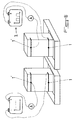
- la figure 2 est une vue en élévation latérale et en coupe d'un mur, montrant l'installation des électrodes faisant partie de l'appareil représenté sur la figure 1 ;
- la figure 3 est une vue selon la direction F du mur représenté sur la figure 2 ;
- les figures 4 et 5 sont des représentations temporelles de signaux impulsionnels de polarités opposées délivrés par l'appareil et appliqués aux électrodes implantées dans le mur à traiter ;
- la figure 6 est une représentation schématique d'une installation permettant un test comparatif de l'appareil selon l'invention avec une source de tension continue, et,
- les figures 7 et 8 représentent des courbes comparatives recueillies au moyen de l'installation de la figure 6, pour des briques en teiTe cuite à trous (figure 7) et des briques en béton cellulaire (figure 8).
- Figure I is a block diagram representation of the apparatus according to the invention;
- Figure 2 is a side elevational view in section of a wall, showing the installation of the electrodes forming part of the apparatus shown in Figure 1;
- Figure 3 is a view in the direction F of the wall shown in Figure 2;
- Figures 4 and 5 are temporal representations of impulse signals of opposite polarities delivered by the device and applied to the electrodes implanted in the wall to be treated;
- FIG. 6 is a schematic representation of an installation allowing a comparative test of the apparatus according to the invention with a DC voltage source, and,
- FIGS. 7 and 8 represent comparative curves collected by means of the installation of FIG. 6, for bricks in baked teiTe (FIG. 7) and bricks in aerated concrete (FIG. 8).
Comme le montrent les figures des dessins annexés, le procédé
d'assèchement de murs, notamment de murs de fondation, est mis en oeuvre au
moyen d'électrodes 1, 1' implantées dans le mur 3 à assécher, comprenant au
moins une cathode 1 et au moins une anode 1', et reliées aux bornes de sortie d'un
dispositif électronique actif 2.As shown in the figures of the accompanying drawings, the process
for dewatering walls, in particular foundation walls, is implemented at
means of
Conformément à l'invention, le procédé d'assèchement consiste à
délivrer des impulsions électriques polarisées, espacées dans le temps. auxdites
électrodes 1, 1', dont la puissance et la durée sont suffisantes pour imposer leur
polarité aux molécules d'eau et aux granules en suspension présents dans la
portion 3' de mur 3 située entre ladite au moins une cathode 1 et ladite au moins
une anode 1'.According to the invention, the dewatering process consists of
deliver polarized electrical pulses, spaced in time. to said
Ainsi, les signaux impulsionnels appliqués aux électrodes 1, 1'
présentent une puissance suffisante pour stopper les déplacements ascendants des
molécules d'eau dans le mur 3 sous l'action de la différence de potentiel présente
naturellement dans ledit mur, tout en permettant à l'appareil de n'être sollicité que
de manière discontinue, pendant les brèves périodes d'application des impulsions
(repérées par I sur les figures 4 et 5), et d'être placé dans un état de repos (repéré
par 2 sur les figures 4 et 5) entre les périodes actives ou temps de travail précités.Thus, the pulse signals applied to the
Il en résulte non seulement une économie substantielle d'énergie, mais également une durée de vie augmentée de l'appareil utilisé.This not only results in substantial energy savings, but also an increased lifespan of the device used.
En fonction de l'état et des conditions d'humidité du mur 3 à traiter,
l'amplitude de la tension des impulsions peut être avantageusement comprise entre
12 V et 3() V, lesdites impulsions étant délivrées avec une intensité pouvant
atteindre 3 A et en étant espacées de quelques millisecondes à quelques dizaines
de secondes.Depending on the state and humidity conditions of the
Selon un mode de réalisation préférentiel de l'invention, ledit
procédé d'assèchement comporte plusieurs phases consécutives préprogrammées
ou réglables manuellement, correspondant chacune à un état déterminé du mur 3 à
traiter et à un paramètrage adapté des impulsions délivrées aux électrodes 1, 1' et
de leur répétition, notamment en ce qui concerne le rapport cyclique des
impulsions délivrées.According to a preferred embodiment of the invention, said
dewatering process includes several consecutive preprogrammed phases
or manually adjustable, each corresponding to a specific state of the
Le rapport cyclique des impulsions appliquées pourra. par exemple. être compris entre 0,2 et 3, préférentiellement entre 0,3 et 2.The duty cycle of the applied pulses may. for example. be between 0.2 and 3, preferably between 0.3 and 2.
La détermination des conditions de traitement en fonction de l'état du
mur 3 pourra être effectuée par des personnes qualifiées. qui procéderont
ultérieurement également à l'installation de l'appareil pour la mise en oeuvre du
procédé selon l'invention et à son étalonnage.The determination of the treatment conditions according to the state of the
Afin de pouvoir traiter des murs 3 quelles que soient la nature du
matériau poreux les constituant et sa composition chimique (qui détermine le
signe et la grandeur des charges électriques des granules dissouts dans le milieu
liquide présent dans lesdits murs 3 à traiter), le procédé prévoit avantageusement
de délivrer aux électrodes 1. 1' des impulsions dont la polarité est opposée à celle
de la différence de potentiel existant naturellement entre les extrémités opposées
de la portion 3' de mur 3 à traiter. In order to be able to process
Ainsi, à titre d'exemples illustratifs, la figure 4 montre un signal comprenant des impulsions à polarité positive (de même type que celle appliquée aux électrodes représentées sur la figure 2), alors que la figure 5 montre un signal comprenant des impulsions à polarité négative.Thus, by way of illustrative examples, FIG. 4 shows a signal comprising pulses with positive polarity (of the same type as that applied to the electrodes shown in Figure 2), while Figure 5 shows a signal comprising pulses of negative polarity.
La présente invention a également pour objet un appareil pour la
mise en oeuvre du procédé de traitement décrit précédemment et comprenant au
moins deux électrodes 1, 1' destinées à être implantées dans le mur 3 à traiter et
reliées à un dispositif électronique actif 2 alimenté par le secteur 10.The present invention also relates to an apparatus for the
implementation of the treatment method described above and comprising at
at least two
Conformément à l'invention, et comme le montre plus
particulièrement la figure 1 des dessins annexés. ledit dispositif 2 est
principalement constitué par un module 4, 5, 6, 7 délivrant des impulsions
électriques polarisantes, associé à des circuits de protection 8 et 9 formant
respectivement interface d'entrée reliée au secteur 10 et interface de sortie reliée
aux électrodes 1, 1'.In accordance with the invention, and as shown more
particularly Figure 1 of the accompanying drawings. said
Selon une caractéristique de l'invention. représentée également à la
figure I des dessins annexés, le module précité est composé de plusieurs unités ou
étages électroniques 4, 5, 6, 7 montés en série et comprenant successivement un
circuit 4 redresseur de tension alternative issue du secteur 10, une cellule 5 de
stabilisation de tension, un circuit 6 hacheur de tension et un circuit 7 de
temporisation.According to a characteristic of the invention. also represented at
Figure I of the accompanying drawings, the aforementioned module is composed of several units or
En vue de limiter au maximum la génération d'interférences
électromagnétiques nuisibles pour l'environnement (notamment pour les appareils
électriques ou électroniques situés dans un voisinage immédiat), d'aboutir à une
structure la moins encombrante possible et de faciliter la production en série à un
coût minimal, il est avantageusement prévu que le dispositif électronique 4, 5, 6,
7, 8, 9 soit dépourvu de tout circuit inductif, ses circuits et unités électroniques
constitutifs étant exclusivement composés de composants actifs et passifs semiconducteurs,
préférentiellement réalisés, autant que possible, sous forme de
circuits intégrés.In order to minimize the generation of interference
electromagnetic harmful to the environment (especially for devices
in the immediate vicinity), to lead to a
space-saving structure possible and to facilitate mass production at a
minimal cost, it is advantageously provided that the
Selon une caractéristique de l'invention, le circuit redresseur 4
intègre une cellule de filtrage et de lissage délivrant une tension continue exempte
de composantes alternatives ou variables.According to a characteristic of the invention, the
En outre, le circuit de protection en sortie 9 comprend une cellule de
filtrage supprimant les composantes de signal impulsionnel pouvant générer des
transitoires susceptibles de perturber l'environnement électromagnétique. De
même, le circuit de protection en entrée 8 pourra également être pourvu d'une
cellule de filtrage. In addition, the output protection circuit 9 includes a
filtering removing the pulse signal components that can generate
transients likely to disturb the electromagnetic environment. Of
even, the
Ledit circuit de protection en entrée 8, destiné à assurer une
protection contre toute surcharge accidentelle, pourra consister en un disjoncteur
différentiel ou en un fusible calibré par exemple, alors que le circuit de protection
en sortie 9, destiné à assurer une protection contre les surcharges ou courts-circuits
accidentels, consistera préférentiellement en un fusible calibré.Said
La cellule 5 de stabilisation fournit à sa sortie une tension constante.
indépendante, dans des limites prédéterminées, de la densité de courant délivré
aux électrodes 1, 1'.The
Il est en effet nécessaire de pouvoir disposer dans certains cas d'une
forte intensité. sous tension constante, ce pour parer à d'éventuels dépôts de
produits d'électrophorèse de longueur réduite sous forte humidité, entre deux
électrodes 1, 1' opposées, équivalents à la mise en place d'une résistance de faible
valeur ohmique entre lesdites électrodes et requérant une forte intensité de courant
en sortie.It is indeed necessary to be able in certain cases to have a
high intensity. under constant voltage, this to prevent possible deposits of
electrophoresis products of reduced length under high humidity, between two
Le circuit 6 hacheur de tension assure le découpage de la tension
continue fournie par la cellule 5 en des impulsions de puissance de polarités
positive ou négative.The 6 voltage chopper circuit ensures voltage cutting
continuous supplied by
Le circuit 7 de temporisation réglable permet quant à lui. par
l'ajustement des constantes R-C, de fixer les valeurs de la durée et du rapport
cyclique des impulsions de puissance fournies aux électrodes 1 et 1'.The
L'ensemble des circuits et cellules électroniques mentionnés précédemment sont parfaitement connus en tant que tels de l'homme du métier et ne nécessitent donc pas d'explications complémentaires précisant leur constitution et leur fonctionnement.All the circuits and electronic cells mentioned previously are perfectly known as such to those skilled in the art and therefore do not require additional explanations specifying their constitution and how they work.
En vue de combattre et d'enrayer l'action de la corrosion électrochimique. associée à la corrosion chimique résultant de la réaction hétérogène entre solide et liquide et attaquant les électrodes en provoquant une perte de matière de ces dernières et une altération de leurs caractéristiques électriques (conduction), il peut être prévu selon l'invention de mettre en oeuvre un ou des moyens de protection mécanique et/ou électronique, ces deux protections pouvant être cumulées pour aboutir à une action protectrice optimale et maximisée.To combat and stop the action of corrosion electrochemical. associated with chemical corrosion resulting from the reaction heterogeneous between solid and liquid and attacking the electrodes causing a loss of material of the latter and an alteration of their characteristics electric (conduction), it can be provided according to the invention to implement one or more mechanical and / or electronic protection means, these two protections that can be combined to achieve optimal protective action and maximized.
Ainsi, selon une caractéristique de l'invention, les électrodes 1, 1'
peuvent être recouvertes ou entourées d'un mélange de résine de copolymère de
butadiène-styrolène (65 % à 90 % en poids) et de poudre de carbone (10 % à 35 %
en poids), assurant une protection mécanique de ces dernières. Thus, according to a characteristic of the invention, the
Les électrodes, qui pourront être de nature quelconque, sont entourées préférentiellement d'un produit de phorèse composé de résine du type Pliolite (nom déposé) de 70 % à 85 %, préférentiellement 80 %, en poids et de poudre de carbone de 15 % à 30 %, préférentiellement 20 %, en poids. Ce mélange s'est montré très efficace dans la protection des électrodes lors de l'application de tensions positives élevées et ce pendant plusieurs mois et possède la double particularité de se durcir dans le temps et d'augmenter sa conductivité électrique en se polymérisant.The electrodes, which may be of any kind, are preferably surrounded by a phoresis product composed of resin of the Pliolite type (registered name) from 70 % to 85%, preferably 80%, by weight and carbon powder of 15%. to 30%, preferably 20%, by weight. This mixture has been shown to be very effective in protecting the electrodes during the application of high positive voltages for several months and has the double characteristic of hardening over time and of increasing its electrical conductivity by polymerizing.
La résine de type Pliolite pourra, par exemple, consister en un ciment colle graphité connu sous la désignation C34 par la société Analab (Hoerdt - France).The Pliolite type resin may, for example, consist of a cement graphite glue known under the designation C34 by the company Analab (Hoerdt - France).
Différentes électrodes (métal et carbone) ont été testées pendant 45 jours par les inventeurs avec ce produit et n'ont pas montré de signes de dégradation tant des électrodes que du produit de phorèse. Sans ce produit de protection, les électrodes se dégradaient relativement rapidement au bout de quelques jours, pour les moins résistantes.Different electrodes (metal and carbon) were tested for 45 days by the inventors with this product and did not show signs of degradation of both the electrodes and the phoresis product. Without this product of protection, the electrodes degraded relatively quickly after a few days, for the less resistant.
Selon une autre caractéristique de l'invention, les impulsions électriques polarisantes. de forme carrée, peuvent être modulées par un signal alternatif de fréquence élevée et d'amplitude faible par rapport à la fréquence et à l'amplitude desdites impulsions polarisantes, assurant ainsi une protection électrique desdites électrodes.According to another characteristic of the invention, the pulses electric polarizers. square, can be modulated by a signal alternating high frequency and low amplitude compared to the frequency and the amplitude of said polarizing pulses, thus ensuring protection electrical of said electrodes.
Cette protection électronique peut consister, plus précisément, à
moduler les signaux carrés par un signal alternatif sinusoïdal de fréquence environ
800 à 1200 Hz, préférentiellement environ 1000 Hz, et d'amplitude 1 à 3 V,
préférentiellement environ 1,5 V, amplitude faible mais suffisante. Ce signal
positif et négatif tous les 1/1000ème de seconde environ, crée un champ électrique
qui permet d'éviter la formation d'un environnement gazeux corrosif autour des
électrodes lorsqu'elles sont placées dans le matériau à protéger.This electronic protection may consist, more specifically, in
modulate square signals with a sinusoidal alternating signal of frequency approximately
800 to 1200 Hz, preferably around 1000 Hz, and of
Ces protections mécaniques et électroniques des électrodes permettent à celles-ci d'être de nature quelconque et donc d'être réalisées à faible coût (métal : acier, fer, cuivre, alu ou carbone). La longévité des électrodes s'en trouve nettement accrue.These mechanical and electronic protections for electrodes allow these to be of any kind and therefore to be performed at low cost (metal: steel, iron, copper, aluminum or carbon). The longevity of the electrodes is finds significantly increased.
Selon une variante de réalisation de l'invention, les électrodes 1 et 1'
consistent en du graphite et sont implantées dans le mur 3 à traiter selon deux
rangées sensiblement parallèles et horizontales délimitant la portion de mur 3' à
traiter, les électrodes I et 1' de chaque rangée étant reliées entre elles par des
saignées 11 remplies d'un mélange conducteur de graphite et d'un liant ou d'un
matériau à prise rapide tel que du plâtre ou du mortier.According to an alternative embodiment of the invention, the
Cette disposition permet de former une cathode 1 et une anode 1'
continues s'étendant sur toute la longueur de la rangée d'électrodes implantées
1 ou 1' correspondante et rendant plus uniformes et plus homogènes les effets liés
à l'inversion de polarité induite par les impulsions de puissance appliquées aux
électrodes I et 1' implantées dans le mur 3.This arrangement makes it possible to form a
Dans la pratique les électrodes 1, 1', pourront être introduites dans le
mur 3 sur une profondeur d'environ 8 à 25 cm en fonction de l'épaisseur dudit mur
et les rangées de cathodes 1 et d'anodes 1' pourront être mutuellement écartées
d'une distance comprise entre 25 cm et 1 m, préférentiellement entre 25 cm et 5()
cm, ce en fonction de l'état du mur 3 à traiter.In practice, the
Afin d'illustrer l'efficacité du procédé et de l'appareil selon l'invention, les inventeurs ont procédé à des tests comparatifs sur des briques rouges en terre cuite (utilisation d'électrodes en graphite) et sur des briques en béton cellulaire (utilisation d'électrodes en Inox - nom déposé).In order to illustrate the effectiveness of the process and the apparatus according to the invention, the inventors carried out comparative tests on bricks red terracotta (use of graphite electrodes) and on bricks aerated concrete (use of stainless steel electrodes - registered name).
Pour chacune de ces expériences, deux briques, préalablement
entièrement trempées dans l'eau pendant 24 h avant leur mise sous test (donc
mouillées identiquement), étaient placées chacune dans un bac contenant de l'eau
dont le niveau était maintenu constant pendant toute la durée de l'observation. Ce
niveau se plaçait juste en dessous de la ligne de cathode. Les deux briques étaient
alors soumises, l'une (témoin) à une tension continue de 3()V, l'autre (sous test) à
une tension impulsionnelle de 30V, délivrée par l'appareil selon l'invention, des
rainures 12 remplies de produit de phorèse s'étendant de part et d'autre desdites
électrodes 1, 1'.For each of these experiments, two bricks, previously
fully soaked in water for 24 hours before being tested (therefore
identically wet), were each placed in a tank containing water
whose level was kept constant throughout the duration of the observation. This
level was located just below the cathode line. The two bricks were
then subjected, one (control) to a DC voltage of 3 () V, the other (under test) to
a pulse voltage of 30V, delivered by the device according to the invention,
Les signaux impulsionnels délivrés par l'appareil selon l'invention étaient conformés de telle manière que la durée de chaque impulsion était environ égale à ().7 seconde et que les intervalles entre impulsions (repos) étaient d'environ 0,3 seconde.The pulse signals delivered by the device according to the invention were shaped so that the duration of each pulse was approximately equal to (). 7 seconds and that the intervals between pulses (rest) were approximately 0.3 seconds.
La forte et rapide diminution de l'intensité constatée sur les briques "sous test" par l'appareil délivrant une tension impulsionnelle, montre une réduction sensible de l'humidité et par conséquent un assèchement accéléré des matériaux.The strong and rapid decrease in intensity observed on the bricks "under test" by the device delivering a pulse voltage, shows a appreciable reduction of humidity and consequently an accelerated drying of materials.
Les courbes de la figure 8 peuvent être approchées par les équations suivantes :
- brique "sous test" :
- brique témoin :
- brick "under test":
- witness brick:
Bien entendu, l'invention n'est pas limitée aux modes de réalisation décrits et représentés aux dessins annexés. Des modifications restent possibles. notamment du point de vue de la constitution des divers éléments ou par substitution d'équivalents techniques, sans sortir pour autant du domaine de protection de l'invention.Of course, the invention is not limited to the embodiments described and shown in the accompanying drawings. Modifications are still possible. in particular from the point of view of the constitution of the various elements or by substitution of technical equivalents, without departing from the scope of protection of the invention.
Claims (11)
Applications Claiming Priority (2)
| Application Number | Priority Date | Filing Date | Title |
|---|---|---|---|
| FR9710837 | 1997-08-27 | ||
| FR9710837A FR2767849B1 (en) | 1997-08-27 | 1997-08-27 | METHOD AND DEVICE FOR DEWATERING WALLS |
Publications (1)
| Publication Number | Publication Date |
|---|---|
| EP0899389A1 true EP0899389A1 (en) | 1999-03-03 |
Family
ID=9510629
Family Applications (1)
| Application Number | Title | Priority Date | Filing Date |
|---|---|---|---|
| EP98440183A Withdrawn EP0899389A1 (en) | 1997-08-27 | 1998-08-25 | Method and apparatus for drying walls |
Country Status (2)
| Country | Link |
|---|---|
| EP (1) | EP0899389A1 (en) |
| FR (1) | FR2767849B1 (en) |
Cited By (1)
| Publication number | Priority date | Publication date | Assignee | Title |
|---|---|---|---|---|
| IT201700112493A1 (en) * | 2017-10-06 | 2019-04-06 | Hardsystem Srl | Equipment and procedure for counteracting rising damp through at least one wall |
Citations (6)
| Publication number | Priority date | Publication date | Assignee | Title |
|---|---|---|---|---|
| EP0111306A2 (en) * | 1982-12-09 | 1984-06-20 | Politechnika Warszawska | Method of drying and protecting masonry against reocurring dampness |
| AT387251B (en) * | 1986-09-18 | 1988-12-27 | Prodinger Karl Dipl Ing Dr | Arrangement for drying masonrywork electroosmotically |
| WO1990010767A1 (en) * | 1989-03-10 | 1990-09-20 | Elcraft A/S | Method and apparatus for controlling the relative humidity in concrete and masonry structures |
| EP0401519A1 (en) * | 1989-06-09 | 1990-12-12 | John B. Miller | Method for electrochemical treatment of porous building materials, particularly for drying and re-alkalization |
| DE4400503A1 (en) * | 1993-01-11 | 1994-07-21 | Christoph Schmidt | Electrochemical moisture barrier, e.g. for masonry |
| WO1997004191A1 (en) * | 1995-07-19 | 1997-02-06 | The Patent Corporation A/S | Method and device for regulating and optimizing transport of humidity by means of electroosmosis |
-
1997
- 1997-08-27 FR FR9710837A patent/FR2767849B1/en not_active Expired - Fee Related
-
1998
- 1998-08-25 EP EP98440183A patent/EP0899389A1/en not_active Withdrawn
Patent Citations (6)
| Publication number | Priority date | Publication date | Assignee | Title |
|---|---|---|---|---|
| EP0111306A2 (en) * | 1982-12-09 | 1984-06-20 | Politechnika Warszawska | Method of drying and protecting masonry against reocurring dampness |
| AT387251B (en) * | 1986-09-18 | 1988-12-27 | Prodinger Karl Dipl Ing Dr | Arrangement for drying masonrywork electroosmotically |
| WO1990010767A1 (en) * | 1989-03-10 | 1990-09-20 | Elcraft A/S | Method and apparatus for controlling the relative humidity in concrete and masonry structures |
| EP0401519A1 (en) * | 1989-06-09 | 1990-12-12 | John B. Miller | Method for electrochemical treatment of porous building materials, particularly for drying and re-alkalization |
| DE4400503A1 (en) * | 1993-01-11 | 1994-07-21 | Christoph Schmidt | Electrochemical moisture barrier, e.g. for masonry |
| WO1997004191A1 (en) * | 1995-07-19 | 1997-02-06 | The Patent Corporation A/S | Method and device for regulating and optimizing transport of humidity by means of electroosmosis |
Cited By (1)
| Publication number | Priority date | Publication date | Assignee | Title |
|---|---|---|---|---|
| IT201700112493A1 (en) * | 2017-10-06 | 2019-04-06 | Hardsystem Srl | Equipment and procedure for counteracting rising damp through at least one wall |
Also Published As
| Publication number | Publication date |
|---|---|
| FR2767849A1 (en) | 1999-03-05 |
| FR2767849B1 (en) | 1999-11-12 |
Similar Documents
| Publication | Publication Date | Title |
|---|---|---|
| EP2839057A1 (en) | Method for the galvanic protection of a reinforced concrete structure | |
| EP2943247B1 (en) | Electrostimulation and/or iontophoresis device with means for varying the voltage as a function of the resistivity of the skin of a user | |
| CA1245710A (en) | Lightning rod with intermittent pulsed corona discharge | |
| EP0847294B1 (en) | Pain relief device through application of electric pulses | |
| CA1281372C (en) | Lightning protection method, means and equipment | |
| EP1453607A1 (en) | Method for treating a nuclear graphite contaminated | |
| EP0899389A1 (en) | Method and apparatus for drying walls | |
| FR2552277A1 (en) | IMPROVEMENTS IN THE CONSTRUCTION OF PARATONERRES | |
| FR2509912A1 (en) | CALCIUM ELECTRO-CHEMICAL BATTERY | |
| CZ61994A3 (en) | Process and apparatus for regeneration of voltage sources performed as primary elements | |
| FR2697950A1 (en) | Low voltage low frequency electrostatic wave generation in soln. - using titanium anode and electrically conducting cathode forming calcium or magnesium titanates when voltage is generated | |
| WO2006072834A3 (en) | Stable electrode and uses thereof | |
| EL‐BELGHITI et al. | Effect of centrifugal force on the aqueous extraction of solute from sugar beet tissue pretreated by a pulsed electric field | |
| Thomson | XXXIX. Experiments on induced-radioactivity in air, and on the electrical conductivity produced in gases when they pass through water | |
| WO2003100932A1 (en) | Method and installation for ionization by electric discharge with dielectric barrier and production of surface-treated substrates | |
| EP0549743A1 (en) | Device for optimizing the discharge of at least two electrochemical generators. | |
| FR2522539A1 (en) | PROCESS FOR THE PROTECTION OF A POWDER COATING FACILITY AGAINST EXPLOSION HAZARD | |
| FR2555366A1 (en) | ELECTRICAL FEEDING DEVICE AMORCABLE BY A LIQUID | |
| EP3938561A1 (en) | Device for forming concretions with regulated autonomous source | |
| FR2809426A1 (en) | Electrical domestic appliance for removing dampness includes circuit generating pulsed low voltage supply to move water by electro-capillary action | |
| FR2565400A1 (en) | Electrochemical double-layer-type capacitor | |
| CH188552A (en) | Gas filter. | |
| FR2903911A1 (en) | Electro-magneto therapy device for e.g. dorsal belt, has source supplying transformer device, and magnets arranged in contact with conductors via surface opposite to another surface that is applied on skin of patient in region to be treated | |
| FR2637986A3 (en) | INSULATION RESISTANCE TESTING DEVICE | |
| Rappich et al. | Influence of hydrogen incorporation into Silicon on the room-temperature photoluminescence |
Legal Events
| Date | Code | Title | Description |
|---|---|---|---|
| PUAI | Public reference made under article 153(3) epc to a published international application that has entered the european phase |
Free format text: ORIGINAL CODE: 0009012 |
|
| AK | Designated contracting states |
Kind code of ref document: A1 Designated state(s): AT BE CH CY DE DK ES FI FR GB GR IE IT LI LU MC NL PT SE |
|
| AX | Request for extension of the european patent |
Free format text: AL;LT;LV;MK;RO;SI |
|
| 17P | Request for examination filed |
Effective date: 19990322 |
|
| AKX | Designation fees paid |
Free format text: AT BE CH CY DE DK ES FI FR GB GR IE IT LI LU MC NL PT SE |
|
| STAA | Information on the status of an ep patent application or granted ep patent |
Free format text: STATUS: THE APPLICATION IS DEEMED TO BE WITHDRAWN |
|
| 18D | Application deemed to be withdrawn |
Effective date: 20020301 |