EP0899389A1 - Verfahren und Vorrichtung zum Trocknen von Wänden - Google Patents
Verfahren und Vorrichtung zum Trocknen von Wänden Download PDFInfo
- Publication number
- EP0899389A1 EP0899389A1 EP98440183A EP98440183A EP0899389A1 EP 0899389 A1 EP0899389 A1 EP 0899389A1 EP 98440183 A EP98440183 A EP 98440183A EP 98440183 A EP98440183 A EP 98440183A EP 0899389 A1 EP0899389 A1 EP 0899389A1
- Authority
- EP
- European Patent Office
- Prior art keywords
- electrodes
- pulses
- wall
- circuit
- treated
- Prior art date
- Legal status (The legal status is an assumption and is not a legal conclusion. Google has not performed a legal analysis and makes no representation as to the accuracy of the status listed.)
- Withdrawn
Links
Images


Classifications
-
- E—FIXED CONSTRUCTIONS
- E04—BUILDING
- E04B—GENERAL BUILDING CONSTRUCTIONS; WALLS, e.g. PARTITIONS; ROOFS; FLOORS; CEILINGS; INSULATION OR OTHER PROTECTION OF BUILDINGS
- E04B1/00—Constructions in general; Structures which are not restricted either to walls, e.g. partitions, or floors or ceilings or roofs
- E04B1/62—Insulation or other protection; Elements or use of specified material therefor
- E04B1/70—Drying or keeping dry, e.g. by air vents
- E04B1/7007—Drying or keeping dry, e.g. by air vents by using electricity, e.g. electro-osmosis
Definitions
- the present invention relates to the building sector, more particularly the treatment of walls, in particular foundations, buildings undergoing infiltration or upwelling, and relates to a process for drying walls and an apparatus for its implementation.
- the main object of the invention is therefore to design a process and an efficient wall drying device with a low operating cost high, in particular with a maximum operating cost / efficiency ratio.
- Another object of the invention is to design an aforementioned device of which the structure is simple, which is easily achievable in a standardized manner large quantity and low cost and whose implementation is safe for the user whatever his qualification.
- Another object of the invention is to design an apparatus mentioned above, the corrosion resistance and the service life of which are notably increased compared to existing devices.
- the subject of the present invention is a method dewatering of walls, in particular of foundation walls, by means of electrodes installed in the wall to be dried, comprising at least one cathode and at least an anode and connected to the output terminals of an active electronic device. characterized in that it consists in delivering polarized electrical pulses, spaced in time, to said electrodes whose power and duration are sufficient to impose their polarity on water molecules and granules in suspension present in the portion of wall located between said at least one cathode and said at least one anode.
- the invention also relates to an apparatus for setting work of the aforementioned treatment method and comprising at least two electrodes intended to be installed in the wall to be treated and connected to a device active electronics powered by the mains, apparatus characterized in that said device mainly consists of a module delivering pulses electric polarizers, associated with protection circuits forming input interface connected to the mains and output interface connected to the electrodes.
- the process for dewatering walls is implemented at means of electrodes 1, 1 ′ implanted in the wall 3 to be dried, comprising at least at least one cathode 1 and at least one anode 1 ', and connected to the output terminals of a active electronic device 2.
- the dewatering process consists of deliver polarized electrical pulses, spaced in time. to said electrodes 1, 1 ', whose power and duration are sufficient to impose their polarity to water molecules and suspended granules present in the portion 3 'of wall 3 located between said at least one cathode 1 and said at least a 1 'anode.
- the pulse signals applied to the electrodes 1, 1 ' have sufficient power to stop the upward movements of the water molecules in wall 3 under the action of the potential difference present naturally in said wall, while allowing the device to be stressed only discontinuously, during the short periods of application of the pulses (marked with I in FIGS. 4 and 5), and to be placed in a state of rest (marked by 2 in Figures 4 and 5) between the aforementioned active periods or working time.
- the amplitude of the pulse voltage can advantageously be between 12 V and 3 () V, said pulses being delivered with an intensity which can reach 3 A and being spaced a few milliseconds to a few tens seconds.
- said dewatering process includes several consecutive preprogrammed phases or manually adjustable, each corresponding to a specific state of the wall 3 to process and adapt the parameters of the pulses delivered to the electrodes 1, 1 'and of their repetition, in particular as regards the duty cycle of pulses delivered.
- the duty cycle of the applied pulses may. for example. be between 0.2 and 3, preferably between 0.3 and 2.
- the determination of the treatment conditions according to the state of the wall 3 may be carried out by qualified persons. who will proceed also after the installation of the device for the implementation of the method according to the invention and its calibration.
- the method advantageously provides to deliver to the electrodes 1. 1 'pulses whose polarity is opposite to that of the potential difference naturally existing between the opposite ends of the portion 3 'of wall 3 to be treated.
- FIG. 4 shows a signal comprising pulses with positive polarity (of the same type as that applied to the electrodes shown in Figure 2)
- Figure 5 shows a signal comprising pulses of negative polarity.
- the present invention also relates to an apparatus for the implementation of the treatment method described above and comprising at at least two electrodes 1, 1 'intended to be installed in the wall 3 to be treated and connected to an active electronic device 2 powered by sector 10.
- said device 2 is mainly constituted by a module 4, 5, 6, 7 delivering pulses electric polarizers, associated with protection circuits 8 and 9 forming input interface connected to sector 10 and output interface respectively at electrodes 1, 1 '.
- the aforementioned module is composed of several units or electronic stages 4, 5, 6, 7 connected in series and successively comprising a circuit 4 AC voltage rectifier from sector 10, a cell 5 of voltage stabilization, a circuit 6 voltage chopper and a circuit 7 of time delay.
- the electronic device 4, 5, 6, 7, 8, 9 is devoid of any inductive circuit, its circuits and electronic units components being exclusively composed of active and passive semiconductor components, preferably made, as much as possible, in the form of integrated circuits.
- the rectifier circuit 4 incorporates a filtering and smoothing cell delivering free DC voltage of alternative or variable components.
- the output protection circuit 9 includes a filtering removing the pulse signal components that can generate transients likely to disturb the electromagnetic environment.
- the input protection circuit 8 may also be provided with a filter cell.
- Said input protection circuit 8 intended to ensure a protection against accidental overload may consist of a circuit breaker differential or a calibrated fuse for example, while the protection circuit at output 9, intended to provide protection against overloads or short-circuits accidental, preferably consists of a calibrated fuse.
- the stabilization cell 5 supplies a constant voltage at its output. independent, within predetermined limits, of the current density delivered at electrodes 1, 1 '.
- the 6 voltage chopper circuit ensures voltage cutting continuous supplied by cell 5 in power pulses of polarities positive or negative.
- the adjustable delay circuit 7 enables. through adjusting R-C constants, setting duration and ratio values cyclic power pulses supplied to electrodes 1 and 1 '.
- the electrodes 1, 1 ' can be covered or surrounded by a mixture of copolymer resin butadiene-styrene (65% to 90% by weight) and carbon powder (10% to 35% by weight), ensuring mechanical protection of the latter.
- the electrodes which may be of any kind, are preferably surrounded by a phoresis product composed of resin of the Pliolite type (registered name) from 70 % to 85%, preferably 80%, by weight and carbon powder of 15%. to 30%, preferably 20%, by weight.
- This mixture has been shown to be very effective in protecting the electrodes during the application of high positive voltages for several months and has the double characteristic of hardening over time and of increasing its electrical conductivity by polymerizing.
- the Pliolite type resin may, for example, consist of a cement graphite glue known under the designation C34 by the company Analab (Hoerdt - France).
- the pulses electric polarizers. square can be modulated by a signal alternating high frequency and low amplitude compared to the frequency and the amplitude of said polarizing pulses, thus ensuring protection electrical of said electrodes.
- This electronic protection may consist, more specifically, in modulate square signals with a sinusoidal alternating signal of frequency approximately 800 to 1200 Hz, preferably around 1000 Hz, and of amplitude 1 to 3 V, preferably around 1.5 V, small but sufficient amplitude.
- This signal positive and negative approximately every 1 / 1000th of a second, creates an electric field which prevents the formation of a corrosive gaseous environment around the electrodes when placed in the material to be protected.
- Electrodes These mechanical and electronic protections for electrodes allow these to be of any kind and therefore to be performed at low cost (metal: steel, iron, copper, aluminum or carbon). The longevity of the electrodes is finds significantly increased.
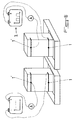
- the electrodes 1 and 1 ' consist of graphite and are installed in wall 3 to be treated according to two substantially parallel and horizontal rows delimiting the wall portion 3 'to to be treated, the electrodes I and 1 ′ of each row being connected together by grooves 11 filled with a conductive mixture of graphite and a binder or a quick setting material such as plaster or mortar.
- This arrangement makes it possible to form a cathode 1 and an anode 1 ' continuous extending over the entire length of the row of implanted electrodes 1 or 1 'corresponding and making the related effects more uniform and homogeneous the polarity reversal induced by the power pulses applied to the electrodes I and 1 'installed in the wall 3.
- the electrodes 1, 1 ′ may be introduced into the wall 3 to a depth of about 8 to 25 cm depending on the thickness of said wall and the rows of cathodes 1 and anodes 1 'can be mutually separated from a distance between 25 cm and 1 m, preferably between 25 cm and 5 () cm, depending on the condition of the wall 3 to be treated.
- the inventors carried out comparative tests on bricks red terracotta (use of graphite electrodes) and on bricks aerated concrete (use of stainless steel electrodes - registered name).
- the pulse signals delivered by the device according to the invention were shaped so that the duration of each pulse was approximately equal to (). 7 seconds and that the intervals between pulses (rest) were approximately 0.3 seconds.
Landscapes
- Engineering & Computer Science (AREA)
- Architecture (AREA)
- Chemical & Material Sciences (AREA)
- Chemical Kinetics & Catalysis (AREA)
- Electrochemistry (AREA)
- Water Supply & Treatment (AREA)
- Physics & Mathematics (AREA)
- Electromagnetism (AREA)
- Civil Engineering (AREA)
- Structural Engineering (AREA)
- Water Treatment By Electricity Or Magnetism (AREA)
Applications Claiming Priority (2)
| Application Number | Priority Date | Filing Date | Title |
|---|---|---|---|
| FR9710837A FR2767849B1 (fr) | 1997-08-27 | 1997-08-27 | Procede et dispositif pour l'assechement de murs |
| FR9710837 | 1997-08-27 |
Publications (1)
| Publication Number | Publication Date |
|---|---|
| EP0899389A1 true EP0899389A1 (de) | 1999-03-03 |
Family
ID=9510629
Family Applications (1)
| Application Number | Title | Priority Date | Filing Date |
|---|---|---|---|
| EP98440183A Withdrawn EP0899389A1 (de) | 1997-08-27 | 1998-08-25 | Verfahren und Vorrichtung zum Trocknen von Wänden |
Country Status (2)
| Country | Link |
|---|---|
| EP (1) | EP0899389A1 (de) |
| FR (1) | FR2767849B1 (de) |
Cited By (1)
| Publication number | Priority date | Publication date | Assignee | Title |
|---|---|---|---|---|
| IT201700112493A1 (it) * | 2017-10-06 | 2019-04-06 | Hardsystem Srl | Attrezzatura e procedimento per contrastare la risalita dell'umidità attraverso almeno una parete |
Citations (6)
| Publication number | Priority date | Publication date | Assignee | Title |
|---|---|---|---|---|
| EP0111306A2 (de) * | 1982-12-09 | 1984-06-20 | Politechnika Warszawska | Verfahren zum Trocknen und Schützen von Mauerwerk vor erneuter Befeuchtung |
| AT387251B (de) * | 1986-09-18 | 1988-12-27 | Prodinger Karl Dipl Ing Dr | Einrichtung zur elektroosmotischen trockenlegung von mauerwerk |
| WO1990010767A1 (en) * | 1989-03-10 | 1990-09-20 | Elcraft A/S | Method and apparatus for controlling the relative humidity in concrete and masonry structures |
| EP0401519A1 (de) * | 1989-06-09 | 1990-12-12 | John B. Miller | Verfahren zur elektrochemischen Behandlung von porösen Baumaterialien, insbesondere für das Trocknen und die Realkalisation |
| DE4400503A1 (de) * | 1993-01-11 | 1994-07-21 | Christoph Schmidt | Elektrochemische Feuchtigkeitssperre |
| WO1997004191A1 (en) * | 1995-07-19 | 1997-02-06 | The Patent Corporation A/S | Method and device for regulating and optimizing transport of humidity by means of electroosmosis |
-
1997
- 1997-08-27 FR FR9710837A patent/FR2767849B1/fr not_active Expired - Fee Related
-
1998
- 1998-08-25 EP EP98440183A patent/EP0899389A1/de not_active Withdrawn
Patent Citations (6)
| Publication number | Priority date | Publication date | Assignee | Title |
|---|---|---|---|---|
| EP0111306A2 (de) * | 1982-12-09 | 1984-06-20 | Politechnika Warszawska | Verfahren zum Trocknen und Schützen von Mauerwerk vor erneuter Befeuchtung |
| AT387251B (de) * | 1986-09-18 | 1988-12-27 | Prodinger Karl Dipl Ing Dr | Einrichtung zur elektroosmotischen trockenlegung von mauerwerk |
| WO1990010767A1 (en) * | 1989-03-10 | 1990-09-20 | Elcraft A/S | Method and apparatus for controlling the relative humidity in concrete and masonry structures |
| EP0401519A1 (de) * | 1989-06-09 | 1990-12-12 | John B. Miller | Verfahren zur elektrochemischen Behandlung von porösen Baumaterialien, insbesondere für das Trocknen und die Realkalisation |
| DE4400503A1 (de) * | 1993-01-11 | 1994-07-21 | Christoph Schmidt | Elektrochemische Feuchtigkeitssperre |
| WO1997004191A1 (en) * | 1995-07-19 | 1997-02-06 | The Patent Corporation A/S | Method and device for regulating and optimizing transport of humidity by means of electroosmosis |
Cited By (1)
| Publication number | Priority date | Publication date | Assignee | Title |
|---|---|---|---|---|
| IT201700112493A1 (it) * | 2017-10-06 | 2019-04-06 | Hardsystem Srl | Attrezzatura e procedimento per contrastare la risalita dell'umidità attraverso almeno una parete |
Also Published As
| Publication number | Publication date |
|---|---|
| FR2767849A1 (fr) | 1999-03-05 |
| FR2767849B1 (fr) | 1999-11-12 |
Similar Documents
| Publication | Publication Date | Title |
|---|---|---|
| WO2004021469A3 (de) | Elektrischer separator mit abschaltmechanismus, verfahren zu dessen herstellung und verwendung in lithium-batterien | |
| CA1245710A (fr) | Paratonnerre a decharge couronne impulsionnelle intermittente | |
| EP0847294B1 (de) | Schmerzlinderungsvorrichtung mittels elektrischen impulsen | |
| CA1281372C (fr) | Procede de protection contre la foudre, moyens pour la mise en oeuvre de ce procede et materiel de protection contre la foudre | |
| EP1453607A1 (de) | Verfahren zur behandlung von kontaminiertem nuklearem graphit | |
| EP0899389A1 (de) | Verfahren und Vorrichtung zum Trocknen von Wänden | |
| FR2552277A1 (fr) | Perfectionnements dans la construction des paratonnerres | |
| FR2509912A1 (fr) | Pile electro-chimique au calcium | |
| CZ61994A3 (en) | Process and apparatus for regeneration of voltage sources performed as primary elements | |
| FR2697950A1 (fr) | Dispositif pour la production de champs électrostatiques de basses tensions dans les solutions aqueuses minéralisées. | |
| WO2006072834A3 (en) | Stable electrode and uses thereof | |
| Thomson | XXXIX. Experiments on induced-radioactivity in air, and on the electrical conductivity produced in gases when they pass through water | |
| WO2003100932A1 (fr) | Procede et installation d'ionisation par decharge electrique a barriere dielectrique et production de substrats traites en surface | |
| EP0549743A1 (de) | Optimierungsvorrichtung für Entladung der zumindest zwei elektrochemischen Stromgeneratoren. | |
| FR2664057A1 (fr) | Procede et dispositif pour l'evaluation de la resistance a la corrosion d'une structure metallique recouverte d'une couche protectrice. | |
| EP3938561B1 (de) | Vorrichtung zur erzeugung von konkrementen mit geregelter autonomer quelle | |
| FR2522539A1 (fr) | Procede pour la protection d'une installation de revetement par poudre contre le risque d'explosion | |
| FR2555366A1 (fr) | Dispositif d'alimentation electrique amorcable par un liquide | |
| FR2809426A1 (fr) | Appareil electrique permettant d'assecher les materiaux de construction soumis aux remontees capillaires et infiltrations laterales d'eau a l'aide de l'action d'electrocapillarite | |
| FR2565400A1 (fr) | Condensateur de type a double couche electrochimique | |
| CH188552A (fr) | Filtre antigaz. | |
| FR2903911A1 (fr) | Dispositif d'electro-magnetotherapie et ceinture le comportant | |
| FR2637986A3 (fr) | Dispositif de controle de la resistance d'isolement | |
| Rappich et al. | Influence of hydrogen incorporation into Silicon on the room-temperature photoluminescence | |
| Mateleshko et al. | Optical properties of SnO2-As2Se3-ZnS (Mn, Cu)-Al structure with intermediate chalcogenide-glass layer |
Legal Events
| Date | Code | Title | Description |
|---|---|---|---|
| PUAI | Public reference made under article 153(3) epc to a published international application that has entered the european phase |
Free format text: ORIGINAL CODE: 0009012 |
|
| AK | Designated contracting states |
Kind code of ref document: A1 Designated state(s): AT BE CH CY DE DK ES FI FR GB GR IE IT LI LU MC NL PT SE |
|
| AX | Request for extension of the european patent |
Free format text: AL;LT;LV;MK;RO;SI |
|
| 17P | Request for examination filed |
Effective date: 19990322 |
|
| AKX | Designation fees paid |
Free format text: AT BE CH CY DE DK ES FI FR GB GR IE IT LI LU MC NL PT SE |
|
| STAA | Information on the status of an ep patent application or granted ep patent |
Free format text: STATUS: THE APPLICATION IS DEEMED TO BE WITHDRAWN |
|
| 18D | Application deemed to be withdrawn |
Effective date: 20020301 |